1982 CHEVROLET CAMARO steering
[x] Cancel search: steeringPage 411 of 875

GM – CAMARO 1982-1992 – Repair Guide (Checked by WxMax) 411
1. Disconnect the negative battery cable.
2. Relieve the fuel system pressure
and drain the engine coolant from the
radiator into a suitable container.
3. Remove the intake manifold and the spark plugs.
4. Remove the dipstick tube and bra cket. Raise and support the vehicle
safely. Drain the oil and remove the oil filter. Lower the vehicle.
5. Remove the exhaust manifolds.
6. Remove the drive belt(s).
7. Remove the air conditioning compresso r and bracket, reposition it aside.
Do not disconnect the lines.
8. Remove the power steering pump and bracket, reposition it aside.
9. Remove the alternator and br acket, reposition it aside.
10. Remove the ground cable from the rear of the cylinder head and remove
the engine lift bracket.
11. Remove the rocker arm covers.
12. Loosen the rocker arms until the pushrods can be removed.
13. Remove the cylinder head bolts and remove the cylinder heads.
To install: 14. Clean the gasket mating surfaces of all components. Be careful not to
nick or scratch any surfaces as this will allow leak paths. Clean the bolt
threads in the cylinder bl ock and on the head bolts. Dirt will affect bolt
torque.
15. Place the head gaskets in pos ition over the dowel pins.
16. Install the cylinder heads.
17. Coat the cylinder head bolts th reads with GM sealer 1052080 or
equivalent, and install the bolts. Tight en the bolts in the proper sequence
to:
• 1982-1987 engines: 70 ft lbs. (90 Nm)
• 1988-1992 engines: 1st step: 40 ft lbs. (55 Nm); 2nd step: tighten
an additional 1/4 (90 degree) turn
18. Install the pushrods a nd loosely retain them wit h the rocker arms. Make
sure the lower ends of the pushrods ar e in the lifter seats. Refer to the
rocker arm procedures outlined ea rlier in this section.
19. Install the power steering pump br acket and pump. Do the same for the
air conditioning compressor bracket and compressor.
20. Install the ground cable to t he rear of the cylinder head.
21. Install the exhaust manifolds.
22. Install the dipstick tube and bracket.
23. Install the intake manifold.
24. Install the alternator bracket and alternator.
25. Install the drive belt(s).
26. Install the spark plugs.
27. Fill the cooling system with the proper type and quantity of coolant. Install
a new oil filter and fill the crankca se with the proper type and quantity of
oil.
28. Connect the negative battery cable, star t the vehicle and check for leaks.
Page 416 of 875

GM – CAMARO 1982-1992 – Repair Guide (Checked by WxMax) 416
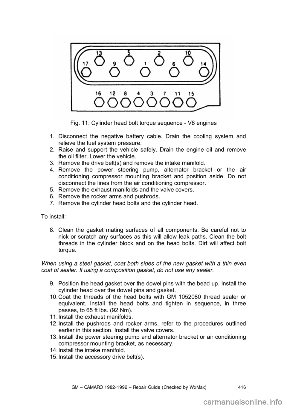
Fig. 11: Cylinder head bolt torque sequence - V8 engines
1. Disconnect the negative battery c able. Drain the cooling system and
relieve the fuel system pressure.
2. Raise and support the vehicle safe ly. Drain the engine oil and remove
the oil filter. Lower the vehicle.
3. Remove the drive belt(s) and remove the intake manifold.
4. Remove the power steering pump, alternator bracket or the air
conditioning compressor mounting br acket and position aside. Do not
disconnect the lines from the air conditioning compressor.
5. Remove the exhaust manifolds and the valve covers.
6. Remove the rocker arms and pushrods.
7. Remove the cylinder head bolts and the cylinder head.
To install: 8. Clean the gasket mating surfaces of all components. Be careful not to
nick or scratch any surfaces as this will allow leak paths. Clean the bolt
threads in the cylinder bl ock and on the head bolts. Dirt will affect bolt
torque.
When using a steel gasket, coat both sides of the new gasket with a thin even
coat of sealer. If using a compos ition gasket, do not use any sealer.
9. Position the head gasket over the dow el pins with the bead up. Install the
cylinder head over the dowel pins and gasket.
10. Coat the threads of the head bo lts with GM 1052080 thread sealer or
equivalent. Install the head bolts and tighten in sequence, in three
passes, to 65 ft lbs. (92 Nm).
11. Install the exhaust manifolds.
12. Install the pushrods and rocker arms, refer to the procedures outlined earlier in this section. Install the valve covers.
13. Install the power steering pump and al ternator bracket or air conditioning
compressor mounting bra cket, as necessary.
14. Install the intake manifold.
15. Install the accessory drive belt(s).
Page 428 of 875

GM – CAMARO 1982-1992 – Repair Guide (Checked by WxMax) 428
1. Disconnect the battery ground c
able. Drain the cooling system.
2. Remove the fan shroud or the upper radiator support and drive belts.
Remove the fan and pulley from the water pump.
3. Remove the alternator upper and lower brackets, air brace with brackets,
and power steering lower bra cket (move it aside).
4. Remove the radiator lower hose and the heater hose from the water
pump. Remove the water pump bolts and the water pump.
5. If A/C equipped, remove the comp ressor and move aside. Remove the
compressor mounting bracket.
6. Remove the damper pulley retain ing bolt and the damper pulley.
7. Remove the timing gear cover bolts and the timing gear cover.
With the timing gear cover removed, use a large screwdriver to pry the oil seal
from the cover. To install the new oil se al, lubricate it with engine oil and drive it
into place.
To install: 8. Prepare the mating surfaces for reinst allation of the timing gear cover.
Coat the new gasket with RTV sealer.
9. Install the timing gear cover and timing gear cover bolts. Torque the
cover bolts to specifications:
• V6 engines (M8 x 1.25 bolts): 13-22 ft. lbs. (18-30 Nm)
• V6 engines (M10 x 1.5 bolts): 20-35 ft. lbs. (27-48 Nm)
• V8 engines (all bolts): 69-130 inch lbs. (8-14 Nm)
10. Install the damper pulley by pulli ng the damper onto the crankshaft. Use
tool J-23523 or equivalent. Install t he damper pulley retaining bolt and
torque bolts to 67-85 ft lbs. (90-110 Nm).
11. If A/C equipped, install the compressor mounting bracket and
compressor.
12. Install the water pump and the water pump bolts.
13. Install the radiator lower hose and the heater hose to the water pump.
14. Install the alternator upper and lower brackets, air brace with brackets
and the power steering lower bracket.
15. Install the fan and pull ey to the water pump. Inst all the fan shroud or the
upper radiator support and drive belts and adjust.
16. Connect the battery ground cable.
17. Fill the cooling syst em, start the engine and check for leaks.
Page 476 of 875

GM – CAMARO 1982-1992 – Repair Guide (Checked by WxMax) 476
Before attempting to repair a threaded
hole, remove any snapped, broken or
damaged bolts or studs. Penetrating oil ca n be used to free frozen threads. The
offending item can usually be removed with locking pliers or using a screw/stud
extractor. After the hole is clear, the thread can be repaired, as shown in the
series of accompanying illustrations and in the kit manufacturer's instructions.
ENGINE PREPARATION
To properly rebuild an engine, you must fi rst remove it from the vehicle, then
disassemble and diagnose it. Ideally you should place your engine on an engine
stand. This affords you the best access to the engine components. Follow the
manufacturer's directions for using the stand with your particular engine.
Remove the flywheel or fl explate before installing the engine to the stand.
Now that you have the engine on a stand, and assuming that you have drained
the oil and coolant from the engine, it's ti me to strip it of all but the necessary
components. Before you start disassembli ng the engine, you may want to take
a moment to draw some pictures, or fabr icate some labels or containers to mark
the locations of various components and the bolts and/or studs which fasten
them. Modern day engines use a lot of littl e brackets and clips which hold wiring
harnesses and such, and these holders are often mounted on studs and/or bolts
that can be easily mixed up. The manufacturer spent a lot of time and money
designing your vehicle, and they wouldn't have wasted any of it by haphazardly
placing brackets, clips or fasteners on t he vehicle. If it's present when you
disassemble it, put it back when you asse mble, you will regret not remembering
that little bracket which holds a wire har ness out of the path of a rotating part.
You should begin by unbolting any accessories still attached to the engine, such
as the water pump, power steering pump, alternator, etc. Then, unfasten any
manifolds (intake or exhaust) which were not removed during the engine
removal procedure. Finally, remove any covers remaining on the engine such
as the rocker arm, front or timing cove r and oil pan. Some front covers may
require the vibration dam per and/or crank pulley to be removed beforehand.
The idea is to reduce the engine to the bar e necessities (cylinder head(s), valve
train, engine block, crankshaft, pistons and connecting rods), plus any other 'in
block' components such as oil pumps, balance shafts and auxiliary shafts.
Finally, remove the cylinder head(s) from the engine block and carefully place
on a bench. Disassembly instructions fo r each component follow later in this
section.
CYLINDER HEAD
There are two basic types of cylinder heads used on today’s automobiles:
the Overhead Valve (OHV) and the Over head Camshaft (OHC). The latter can
also be broken down into two subgr oups: the Single Overhead Camshaft
(SOHC) and the Dual Overhead Camshaft (DO HC). Generally, if there is only a
single camshaft on a head, it is just referred to as an OHC head. Also, an
engine with a OHV cylinder head is also known as a pushrod engine.
Page 573 of 875

GM – CAMARO 1982-1992 – Repair Guide (Checked by WxMax) 573
7. Install the retaining bracket.
8. Connect the negative battery cable.
ELECTRONIC ENGINE CONTROLS
COMPUTER COMMAND CO NTROL (CCC) SYSTEM
The Computer Command Control (CCC) Sy stem is an electronically controlled
exhaust emission system that can m onitor and control a large number of
interrelated emission cont rol systems. It can monitor various engine/vehicle
operating conditions and then use this in formation to control multiple engine
related systems. The CCC syst em is thereby making constant adjustments to
maintain optimum vehicle performance und er all normal driving conditions while
at the same time allowing the catalyti c converter to effectively control the
emissions of HC, CO and NO
x.
OPERATION
The Electronic Control Module (ECM) is required to maintain the exhaust
emissions at acceptable le vels. The module is a sma ll, solid state computer
which receives signals from many source s and sensors; it uses these data to
make judgements about operating conditions and then control output signals to
the fuel and emission systems to ma tch the current requirements.
Inputs are received from m any sources to form a complete picture of engine
operating conditions. Some inputs are simp ly Yes or No messages, such as that
from the Park/Neutral switch; the vehicle is either in gear or in Park/Neutral;
there are no other choices. Other data is sent in quantitative input, such as
engine rpm or coolant temperature. T he ECM is pre-programmed to recognize
acceptable ranges or combinations of si gnals and control the outputs to control
emissions while providing good driv eability and economy. The ECM also
monitors some output circuits, making sure that the components function as
commanded. For proper engine oper ation, it is essential that all input and output
components function properly and comm unicate properly with the ECM.
Since the control module is programmed to recognize the presence and value
of electrical inputs, it will also note the lack of a signal or a radical change in
values. It will, for example, react to the loss of signal from the vehicle speed
sensor or note that engine coolant temperature has risen beyond acceptable
(programmed) limits. Once a fault is recognized, a numeric code is assigned
and held in memory. The SERVICE ENGIN E SOON Malfunction Indicator Lamp
(MIL), will illuminate to advise the operator that the system has detected a fault.
More than one code may be stored. Although not every engine uses every
code, possible codes range from 12-999. Additionally, the same code may carry
different meanings relative to each engine or engine family. For example, on the
3.3L (VIN N) engine, code 46 indicates a fault found in the power steering
pressure switch circuit. The same code on the 5.7L (VIN F) engine indicates a
fault in the VATS anti-theft system.
Page 799 of 875

GM – CAMARO 1982-1992 – Repair Guide (Checked by WxMax) 799
The master cylinder is located in
the left rear section of the engine
compartment. The brake master cylinder consists of an aluminum body and a
translucent nylon reservoir with minimum fill indicators.
1. Check the master cylinder body for cracks. Inspect the area around the
master cylinder for brake fluid. Leaks are indicated if there is at least a
drop of fluid. A damp condition is not normal.
2. Inspect the level of the brake fluid to assure it is at the correct height.
Clean the top of the reservoir cap so t hat all dirt is removed. Remove the
cap(s) or reservoir cover and the reservoir diaphragm.
3. Inspect the brake fluid level. Add clean DOT-3 brake fluid as required to
bring the fluid level to the line located inside the neck of the reservoir fill
opening.
4. Install the reservoir cap.
WARNING - Any sudden decrease in the fluid level indicates a possible leak in
the system and should be check ed out immediately. Do not allow brake fluid to
spill on the vehicle's finish; it will remove the paint. In case of a spill, flush the
area with water and mild soap.
HYDRAULIC CLUTCH SYSTEM
FLUID RECOMMENDATIONS
• 1982-1991 - Delco Supreme II Brake fl uid or an equivalent fluid that
meets DOT-3 specifications
• 1992 - Hydraulic clutch fluid, GM part number 12345347 or equivalent
LEVEL CHECK
The clutch master cylinder is normally lo cated below the brake master cylinder.
The reservoir for it is located right bes ide the brake master cylinder and is made
of translucent nylon. The fl uid level of the reservoir sh ould be kept near the top
of the observation window. Before removing the cap to the reservoir, clean all
dirt from the area. This will prevent syst em contamination due to particles falling
into the reservoir when the caps are removed.
POWER STEERING PUMP
FLUID RECOMMENDATIONS
• GM power steering fluid, or equivalent.
Page 800 of 875

GM – CAMARO 1982-1992 – Repair Guide (Checked by WxMax) 800
LEVEL CHECK
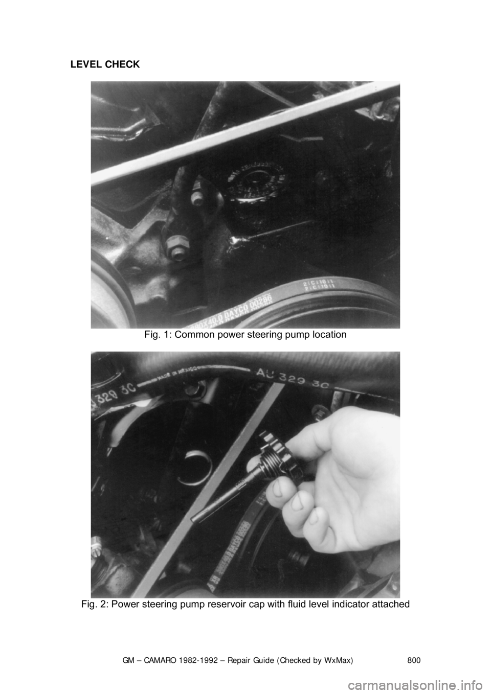
Fig. 1: Common power steering pump location
Fig. 2: Power steering pump reservoir cap with fluid level indicator attached
Page 801 of 875

GM – CAMARO 1982-1992 – Repair Guide (Checked by WxMax) 801
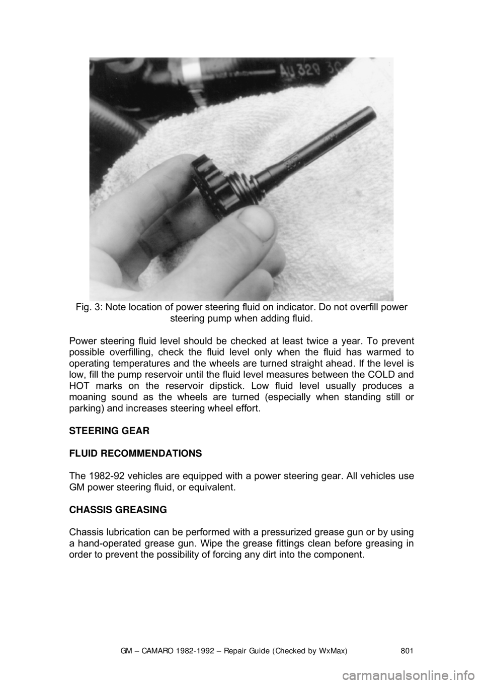
Fig. 3: Note location of power steering fluid on indicator. Do not overfill power
steering pump when adding fluid.
Power steering fluid level s hould be checked at least twice a year. To prevent
possible overfilling, check the fluid le vel only when the fluid has warmed to
operating temperatures and the wheels are turned straight ahead. If the level is
low, fill the pump reservoir until the flui d level measures between the COLD and
HOT marks on the reservoir dipstick. Low fluid level usually produces a
moaning sound as the wheels are turned (especially when standing still or
parking) and increases st eering wheel effort.
STEERING GEAR
FLUID RECOMMENDATIONS
The 1982-92 vehicles are equipped with a pow er steering gear. All vehicles use
GM power steering fluid, or equivalent.
CHASSIS GREASING
Chassis lubrication can be performed with a pressurized grease gun or by using
a hand-operated grease gun. Wipe the grease fittings clean before greasing in
order to prevent the possibility of fo rcing any dirt into the component.