Page 11 of 875

GM – CAMARO 1982-1992 – Repair Guide (Checked by WxMax) 11
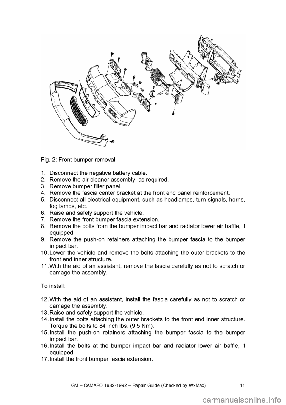
Fig. 2: Front bumper removal
1. Disconnect the negative battery cable.
2. Remove the air cleaner assembly, as required.
3. Remove bumper filler panel.
4. Remove the fascia center bracket at the front end panel reinforcement.
5. Disconnect all electrical equipment, su ch as headlamps, turn signals, horns,
fog lamps, etc.
6. Raise and safely support the vehicle.
7. Remove the front bumper fascia extension.
8. Remove the bolts from the bumper impac t bar and radiator lower air baffle, if
equipped.
9. Remove the push-on retainers attach ing the bumper fascia to the bumper
impact bar.
10. Lower the vehicle and remove the bolt s attaching the outer brackets to the
front end inner structure.
11. With the aid of an assistant, remove t he fascia carefully as not to scratch or
damage the assembly.
To install:
12. With the aid of an assistant, install t he fascia carefully as not to scratch or
damage the assembly.
13. Raise and safely support the vehicle.
14. Install the bolts attachi ng the outer brackets to the front end inner structure.
Torque the bolts to 84 inch lbs. (9.5 Nm).
15. Install the push-on retainers atta ching the bumper fascia to the bumper
impact bar.
16. Install the bolts at t he bumper impact bar and radiat or lower air baffle, if
equipped.
17. Install the front bum per fascia extension.
Page 12 of 875

GM – CAMARO 1982-1992 – Repair Guide (Checked by WxMax) 12
18. Connect all electrical equipment, such
as headlamps, turn signals, horns,
fog lamps, etc.
19. Install the fascia center bracket at the front end panel reinforcement.
20. Install bumper filler panel.
21. Install the air cleaner assembly, as required.
22. Connect the negative battery cable.
REAR
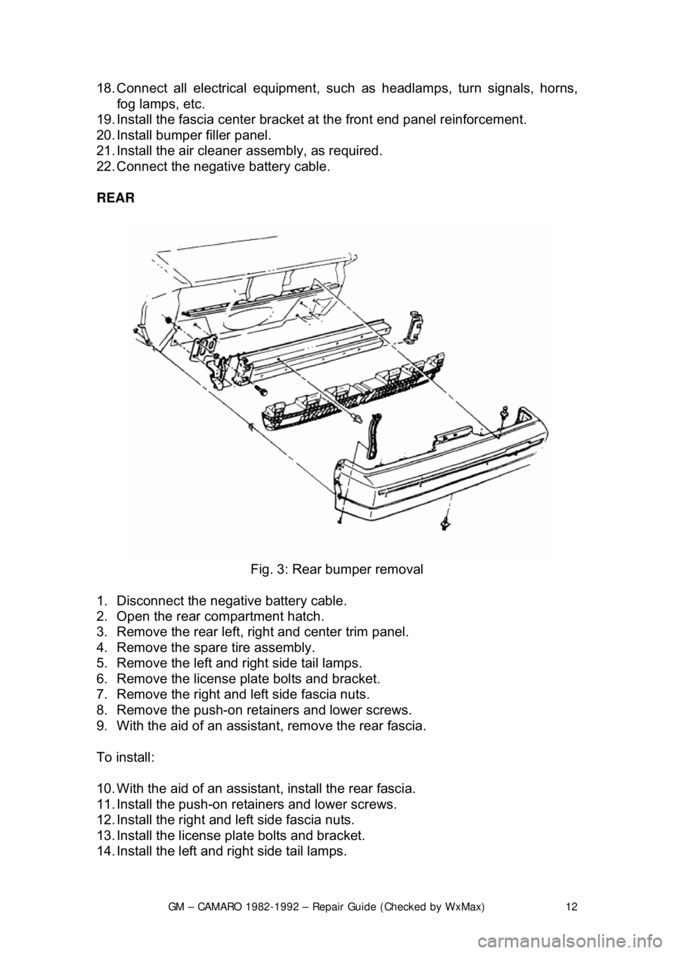
Fig. 3: Rear bumper removal
1. Disconnect the negative battery cable.
2. Open the rear compartment hatch.
3. Remove the rear left, ri ght and center trim panel.
4. Remove the spare tire assembly.
5. Remove the left and right side tail lamps.
6. Remove the license plate bolts and bracket.
7. Remove the right and left side fascia nuts.
8. Remove the push-on retainers and lower screws.
9. With the aid of an assistan t, remove the rear fascia.
To install:
10. With the aid of an assistan t, install the rear fascia.
11. Install the push-on retainers and lower screws.
12. Install the right and left side fascia nuts.
13. Install the license plate bolts and bracket.
14. Install the left and right side tail lamps.
Page 16 of 875

GM – CAMARO 1982-1992 – Repair Guide (Checked by WxMax) 16
8. Remove the front end bumper fa
scia-to-fender nuts and screws.
9. Remove the hood hinge-to-fender bolts.
10. Disconnect all electrical connections from horn, turn signal lamps, etc.
11. Remove the fender by sliding rearward and outward, at rear, with the aid of
an assistant. Place an old blanket over the fender as to avoid scratches or
dents.
To install:
12. Install the fender with the aid of an assistant. Plac e an old blanket over the
fender as to avoid scratches or dents.
13. Connect all electrical connections to the horn, turn signal lamps, etc.
14. Install the hood hinge-to-fender bolts.
15. Install the front end bumper fascia-to-fender nuts and screws.
16. Install the bolt at the support brace.
17. Install the lower front end panel deflector-to-fender bolts.
18. Install the rocker panel molding.
19. Install the lower fender bol ts and inner wheel house panel.
20. Install the hood.
21. Disconnect the negative battery cable. Align the fender and hood as
necessary, placing existing shims in original positions.
Page 169 of 875

GM – CAMARO 1982-1992 – Repair Guide (Checked by WxMax) 169
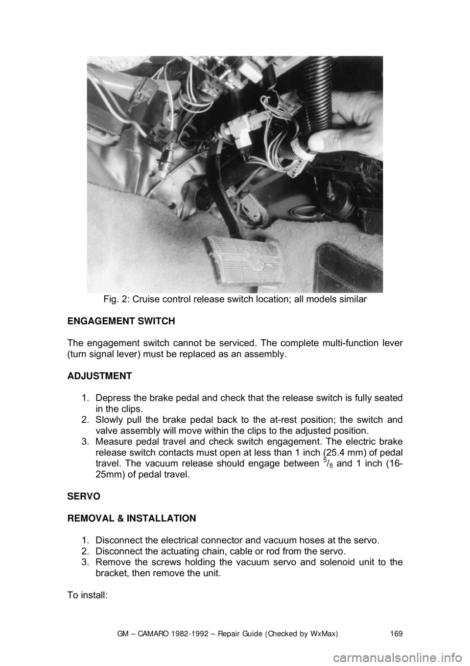
Fig. 2: Cruise control release sw itch location; all models similar
ENGAGEMENT SWITCH
The engagement switch cannot be serviced . The complete multi-function lever
(turn signal lever) must be replaced as an assembly.
ADJUSTMENT
1. Depress the brake pedal and check that the release switch is fully seated
in the clips.
2. Slowly pull the brake pedal back to the at-rest position; the switch and
valve assembly will move within the clips to the adjusted position.
3. Measure pedal travel and check s witch engagement. The electric brake
release switch contacts must open at less than 1 inch (25.4 mm) of pedal
travel. The vacuum release should engage between
5/8 and 1 inch (16-
25mm) of pedal travel.
SERVO
REMOVAL & INSTALLATION 1. Disconnect the electrical connecto r and vacuum hoses at the servo.
2. Disconnect the actuating chain, cable or rod from the servo.
3. Remove the screws holding the vac uum servo and solenoid unit to the
bracket, then remove the unit.
To install:
Page 209 of 875
GM – CAMARO 1982-1992 – Repair Guide (Checked by WxMax) 209
SIGNAL AND MARKER LIGHTS
REMOVAL & INSTALLATION
FRONT PARKING AND TURN SIGNAL
Reach around to the back side of t
he light assembly and unlock the bulb
holder/wiring harness by grasping the bul b holder/wiring harness and turning it
counterclockwise approximately
1/4 turn.
1. Remove the bulb holder/wiring harness assembly.
2. To install, insert the bulb holder /wiring harness assembly into the light
assembly and locking the holder by turning it
1/4 turn clockwise.
Fig. 1: Typical front turn signal lamp mounting
FRONT MARKER LIGHTS 1. Remove the six screws from the filler panel under the front fascia.
2. Remove the filler panel.
3. Remove the socket from the lamp assembly.
4. Remove the bulb from the socket.
5. Installation is the reverse of removal.
Page 211 of 875
GM – CAMARO 1982-1992 – Repair Guide (Checked by WxMax) 211
Fig. 4: Once the filler panel has been remo ved, the front side marker light can
be replaced
REAR MARKER LIGHTS 1. Open the hatch.
2. Remove the fasteners from the rear trim panel.
3. Remove the trim panel.
4. Remove the socket from the lens assembly.
5. Remove the bulb from the socket.
6. Installation is the reverse of removal.
Fig. 5: Exploded view of the side marker lamp assembly
REAR TURN SIGNAL, BRAKE AND PARKING LIGHTS
Page 224 of 875
GM – CAMARO 1982-1992 – Repair Guide (Checked by WxMax) 224
BUZZERS, RELAYS, AND FLASHERS
The electrical protection dev
ices are located in the convenience center, which is
a swing down unit located under the inst rument panel. All units are serviced by
plug-in replacements.
TURN SIGNAL FLASHER
The turn signal flasher is located inside th e convenience center. In order to gain
access to the turn signal flasher, it ma y be necessary to first remove the under
dash padding.
HAZARD FLASHER
The hazard flasher is located inside the convenience center. In order to gain
access to the turn signal flasher, it ma y be necessary to first remove the under
dash padding.
Page 298 of 875
GM – CAMARO 1982-1992 – Repair Guide (Checked by WxMax) 298
Fig. 2: Clutch pedal with mechanical linkage
5. Disconnect and remove the neutra l start switch at the pedal.
6. Remove the turn signal and hazard warning flasher mounting bracket.
7. Disconnect the clutch pedal rod from the pedal.
8. Remove the clutch pedal pivot bolt far enough to permit removal of pedal\
assembly.
9. Clean all parts and relubricate. Install in reverse of removal.
CLUTCH LINKAGE
REMOVAL & INSTALLATION 1. Disconnect the negative battery cable.
2. Disconnect the return spring and rods from the pedal and fork assembly.