1982 CHEVROLET CAMARO torque
[x] Cancel search: torquePage 734 of 875

GM – CAMARO 1982-1992 – Repair Guide (Checked by WxMax) 734
5. Install the throttle position sensor
. Make sure the TPS pickup lever is
located above the tang on the throttle actuator lever.
6. Install the TPS attaching screws.
7. Adjust the TPS voltage.
8. Reconnect the electrical connector.
9. Install the air cleaner.
IDLE AIR CONTROL VALVE
REMOVAL & INSTALLATION 1. Remove the air cleaner.
2. Detach the electrical connection fr om the idle air control assembly.
3. Using a 1
1/4 in. wrench, remove the IAC valve from the throttle body. On
IAC valves secured with screws, remove the attaching screws.
Before installing a NEW IAC valve, measur e the distance that the conical valve
is extended. Measurement should be made from the motor housing to the end
of the cone. Distance s hould be no greater than 1
1/4 in. (32mm). If the cone is
extended too far, damage may result when the motor is installed. If necessary,
push on the end of cone until it is retracted the correct distance.
4. Installation is the reverse of remo val. Torque threaded valves to 13 ft.
lbs. (17 Nm).
Fig. 1: IAC valve pintle measurement
Page 761 of 875

GM – CAMARO 1982-1992 – Repair Guide (Checked by WxMax) 761
MAINTENANCE OR REPAIR?
Maintenance includes routine inspecti
ons, adjustments, and replacement of
parts which show signs of normal wear . Maintenance compensates for wear or
deterioration. Repair implies that someth ing has broken or is not working. A
need for a repair is often caused by lack of maintenance. for example: draining
and refilling automatic transmission fl uid is maintenance recommended at
specific intervals. Failure to do this can shorten the life of the
transmission/transaxle, requiring very expen sive repairs. While no maintenance
program can prevent items from eventually breaking or wearing out, a general
rule is true: MAINTENANCE IS CHEAPER THAN REPAIR.
Two basic mechanic's rules should be mentioned here. First, whenever the left
side of the vehicle or engine is refe rred to, it means the driver's side.
Conversely, the right side of the vehi cle means the passenger's side. Second,
screws and bolts are removed by turn ing counterclockwise, and tightened by
turning clockwise unless specifically noted.
Safety is always the most important rule. Constantly be aware of the dangers
involved in working on an automobile and take the proper precautions. Please
refer to the information in this se ction regarding SERVICING YOUR VEHICLE
SAFELY and the SAFETY NOTICE on the acknowledgment page.
AVOIDING THE MOST COMMON MISTAKES
Pay attention to the instructions prov ided. There are 3 common mistakes in
mechanical work:
1. Incorrect order of assembly, di sassembly or adjustment. When taking
something apart or putting it toget her, performing steps in the wrong
order usually just costs you ex tra time; however, it CAN break
something. Read the entire proc edure before beginning. Perform
everything in the order in which the instructions say you should, even if
you can't see a reason for it. When you' re taking apart something that is
very intricate, you might want to draw a picture of how it looks when
assembled in order to make sure you get everything back in its proper
position. When making adjustments, per form them in the proper order.
One adjustment possibly will affect another.
2. Overtorquing (or undertorquing). While it is more common for overtorquing to cause damage, undertorquing may allow a fastener to
vibrate loose causing serious dam age. Especially when dealing with
aluminum parts, pay attention to tor que specifications and utilize a torque
wrench in assembly. If a torque figure is not available, remember that if
you are using the right tool to perfo rm the job, you will probably not have
to strain yourself to get a fast ener tight enough. The pitch of most
threads is so slight that the te nsion you put on the wrench will be
multiplied many times in actual fo rce on what you are tightening.
There are many commercial products avai lable for ensuring that fasteners won't
come loose, even if they are not torqued just right (a very common brand is
Page 762 of 875

GM – CAMARO 1982-1992 – Repair Guide (Checked by WxMax) 762
Loctite). If you're worried about getting so
mething together tight enough to hold,
but loose enough to avoid mechanical damage during assembly, one of these
products might offer substantial insurance. Before choosing a threadlocking
compound, read the label on the pa ckage and make sure the product is
compatible with the materials, fluids, etc. involved.
3. Crossthreading. This occu rs when a part such as a bolt is screwed into a
nut or casting at the wrong angle and forced. Cr ossthreading is more
likely to occur if access is diffic ult. It helps to clean and lubricate
fasteners, then to start threading the bolt, spark pl ug, etc. with your
fingers. If you encounter resistance, unscrew the part and start over
again at a different angle until it can be inserted and turned several t\
imes
without much effort. Keep in mind t hat many parts have tapered threads,
so that gentle turning will automatica lly bring the part you're threading to
the proper angle. Don't put a wrench on the part until it's been tightened
a couple of turns by hand. If you s uddenly encounter resistance, and the
part has not seated fully, don't force it. Pull it back out to make sure it's
clean and threading properly.
Be sure to take your time and be pati ent, and always plan ahead. Allow yourself
ample time to perform r epairs and maintenance.
TOOLS AND EQUIPMENT
Without the proper tools and equipment it is impossible to properly service your
vehicle. It would be virtually impossible to catalog every tool that you would
need to perform all of the oper ations in this repair guide. It would be unwise for
the amateur to rush out and buy an expens ive set of tools on the theory that
he/she may need one or more of them at some time.
The best approach is to proceed slowly, gathering a good quality set of those
tools that are used most frequently. Don't be misled by the low cost of bargain
tools. It is far better to spend a little more for better quality. Forged wrenches, 6
or 12-point sockets and fine tooth ratc hets are by far preferable to their less
expensive counterparts. As any good me chanic can tell you, there are few
worse experiences than trying to work on a vehicle with bad tools. Your
monetary savings will be far outweighed by frustration and mangled knuckles.
Begin accumulating those tools that are used most frequently: those associated
with routine maintenance and tune-up. In addition to the normal assortment of
screwdrivers and pliers, you should have the following tools:
• Wrenches/sockets and combination o pen end/box end wrenches in sizes 1/83/4 in. and/or 3mm-19mm 13/16 in. or 5/8 in. spark plug socket
(depending on plug type).
If possible, buy various length socket drive extensions. Universal-joint\
and
wobble extensions can be extremely usef ul, but be careful when using them, as
they can change the amount of torque applied to the socket.
Page 765 of 875

GM – CAMARO 1982-1992 – Repair Guide (Checked by WxMax) 765
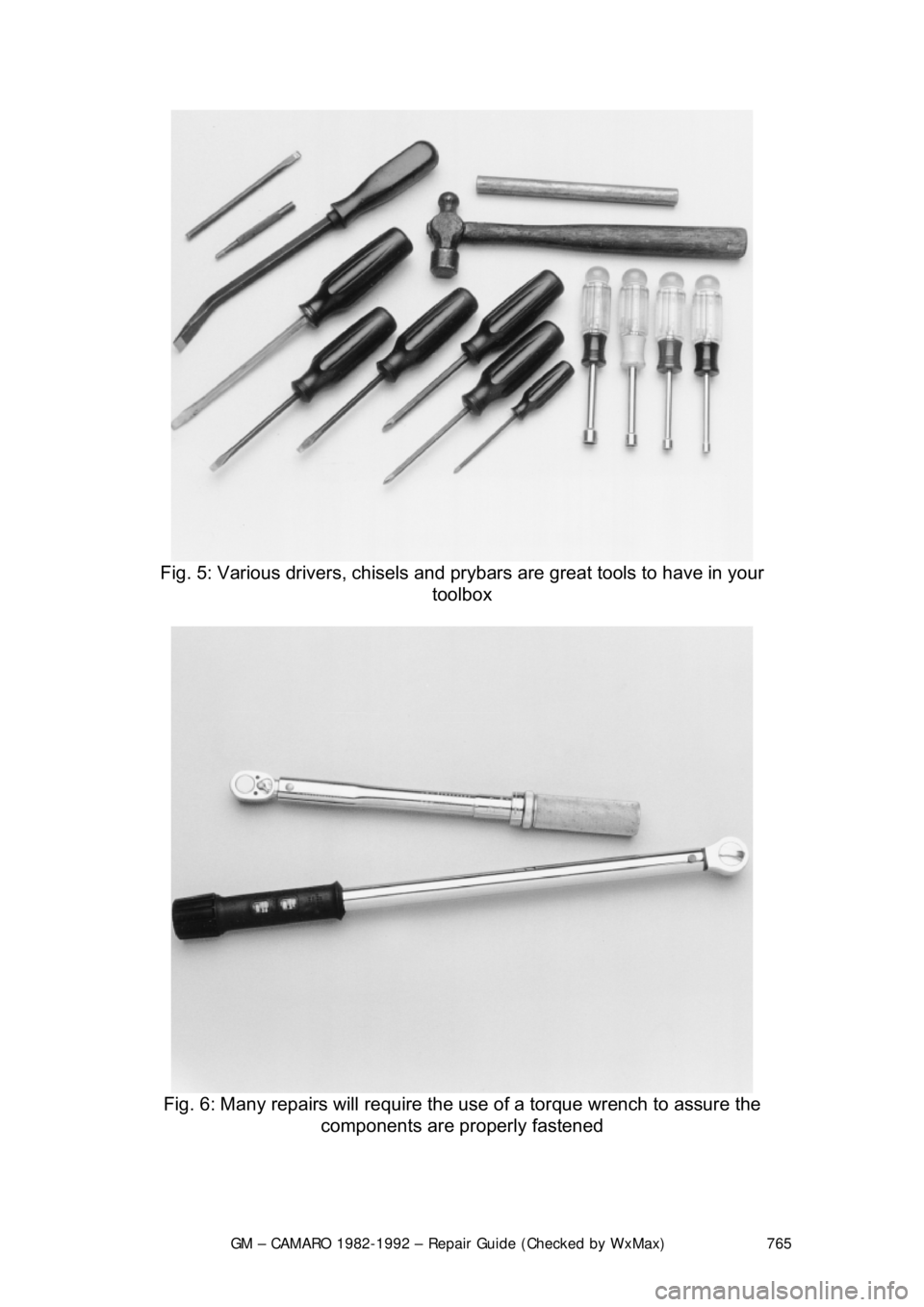
Fig. 5: Various drivers, chisels and pr ybars are great tools to have in your
toolbox
Fig. 6: Many repairs will require the us e of a torque wrench to assure the
components are properly fastened
Page 771 of 875

GM – CAMARO 1982-1992 – Repair Guide (Checked by WxMax) 771
A more advanced set of tools, suit
able for tune-up work, can be drawn up
easily. While the tools are slightly more sophisticated, they need not be
outrageously expensive. There are severa l inexpensive tach/dwell meters on
the market that are every bit as good for the average mechanic as a
professional model. Just be sure that it goes to a least 1200-1500 rpm on the
tach scale and that it works on 4, 6 and 8-cylinder engines. The key to these
purchases is to make them with an eye towards adaptability and wide range. A
basic list of tune-up tools could include:
• Tach/dwell meter.
• Spark plug wrench and gapping tool.
• Feeler gauges for valve adjustment.
• Timing light.
The choice of a timing light should be made carefully. A light which works on the
DC current supplied by the vehicle's battery is the best choice; it should have a
xenon tube for brightness. On any vehi cle with an electronic ignition system, a
timing light with an inductive pickup that clamps around the No. 1 spark plug
cable is preferred.
In addition to these basic tools, ther e are several other tools and gauges you
may find useful. These include:
• Compression gauge. The screw-in type is slower to use, but eliminates
the possibility of a faulty r eading due to escaping pressure.
• Manifold vacuum gauge.
• 12V test light.
• A combination volt/ohmmeter
• Induction Ammeter. This is used for determining whether or not there is
current in a wire. These are handy fo r use if a wire is broken somewhere
in a wiring harness.
As a final note, you will probably find a torque wrench necessary for all but the
most basic work. The beam type models are perfectly adequate, although the
newer click types (breakaway) are eas ier to use. The click type torque
wrenches tend to be more expensive. Also keep in mind that all types of torque
wrenches should be periodically checked a nd/or recalibrated. You will have to
decide for yourself which better fits your pocketbook, and purpose.
SPECIAL TOOLS
Normally, the use of special factory tool s is avoided for repair procedures, since
these are not readily available for the do-it-yourself mechanic. When it is
possible to perform the job with more co mmonly available tools, it will be
pointed out, but occasionally, a special t ool was designed to perform a specific
function and should be used. Before s ubstituting another tool, you should be
convinced that neither your safety nor the performance of the vehicle will be
compromised.
Page 791 of 875

GM – CAMARO 1982-1992 – Repair Guide (Checked by WxMax) 791
3. Clean all dirt from
the area around the cover. Re move the bolts retaining
the cover to the housing. Pry the co ver from the differential housing and
allow the fluid to drain into the catch pan.
To install: 4. With the cover and housing washed free of oil and gasket material, apply sealer to the mating surfaces.
5. Using a new gasket, install the cove r and torque the bolts to 20 ft. lbs.
(27 Nm) in a clockwise pattern to in sure uniform draw on the gasket. Fill
the differential with fluid through the fi ll plug and add limited slip additive,
as required.
6. Install the parking brake cable guides, if removed.
7. The fluid level shou ld reached a level within
3/8 in. (10mm) of the filler
plug hole. Replace the filler plug. Low er the car and inspect for leaks.
COOLING SYSTEM
CAUTION - When draining the c oolant, keep in mind that cats and dogs are
attracted by the ethylene gl ycol antifreeze, and are quite likely to drink any that
is left in an uncovered container or in puddles on the ground. This will prove
fatal in sufficient quantity. Always drai n the coolant into a sealable container.
Coolant should be reused unless it is c ontaminated or several years old (in
which case it should be taken to a recycli ng facility such as a service station).
FLUID RECOMMENDATIONS
When adding or changing the fluid in the system, create a 50/50 mixture of high
quality ethylene glycol antifreeze and water.
LEVEL CHECK
Fig. 1: Fluid level marks on the cool ant recovery tank. With a warm system,
coolant level should be just below the FULL HOT mark on tank.
Page 803 of 875

GM – CAMARO 1982-1992 – Repair Guide (Checked by WxMax) 803
5. Pry out the inner seal and
remove the inner bearing.
6. Wipe out the grease from inside the hub.
7. Clean the wheel bearings thor oughly with solvent and check their
condition before installation. Afte r cleaning, check parts for excessive
wear and replace damaged parts.
WARNING - Do not allow the bearing to spin when blowing dry with
compressed air, as this would allow t he bearing to turn without lubrication.
8. Apply a sizable amount of lubricant to the palm of one hand. Using your
other hand, work the bearing into the lubricant so that the grease is
pushed through the rollers and out t he other side. Keep rotating the
bearing while continuing to push the lubricant through it.
9. Apply grease to the inside of t he hub and install the inner bearing in the
hub. Install a new grease seal, be careful not to damage the seal.
10. Install the disc/hub assembly onto t he steering knuckle. Install the outer
bearing, thrust washer and castle nu t. Torque the nut to 12 ft. lbs. (16
Nm) while turning the wheel.
11. Back the nut off and retighten it by hand until nearest slot aligns with the
cotter pin hole.
12. Insert a new cotter pin.
13. Mount a dial indicator onto the vehi cle so that any end-play in the hub
can be measured. Measure the end-play and record the value. End-play
should be between 0.001-0.005 in. (0.025- 0.127mm). If play exceeds this
tolerance, the wheel bearings should be replaced.
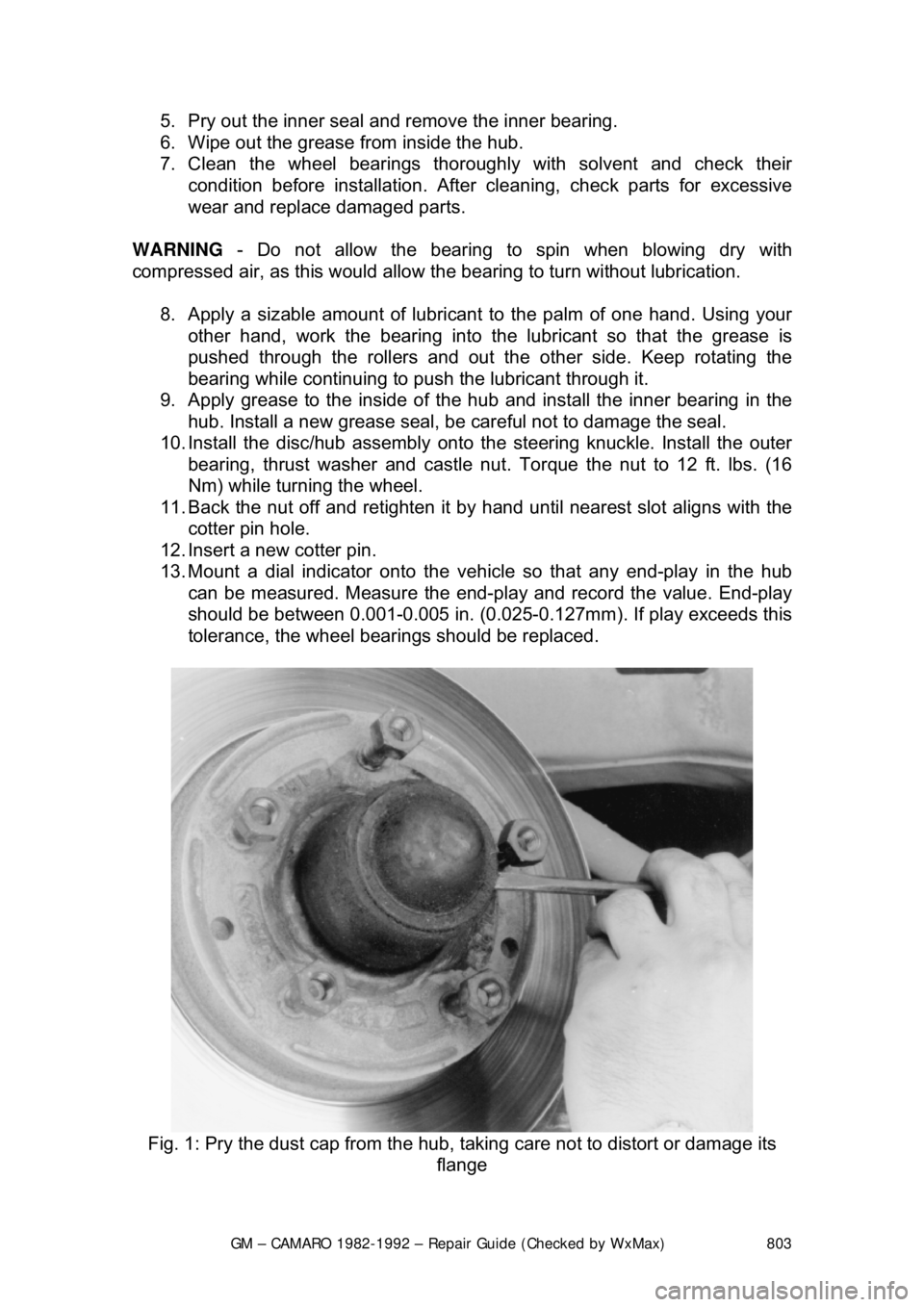
Fig. 1: Pry the dust cap fr om the hub, taking care not to distort or damage its
flange
Page 818 of 875

GM – CAMARO 1982-1992 – Repair Guide (Checked by WxMax) 818
•
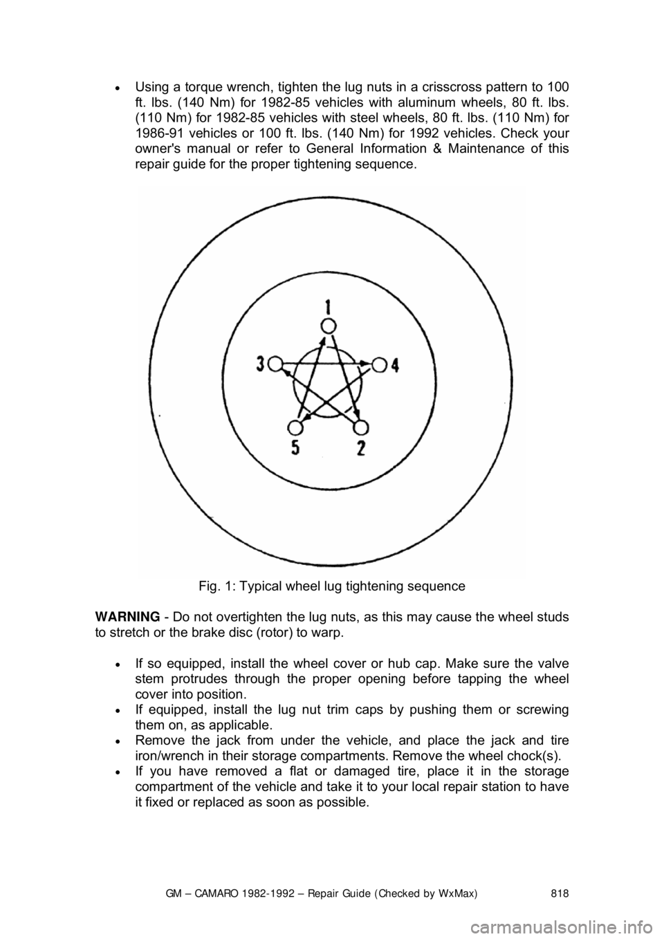
Using a torque wrench, tighten the lug nuts in a crisscross pattern to 100
ft. lbs. (140 Nm) for 1982-85 vehicles with aluminum wheels, 80 ft. lbs.
(110 Nm) for 1982-85 vehicles with st eel wheels, 80 ft. lbs. (110 Nm) for
1986-91 vehicles or 100 ft. lbs. (140 Nm) for 1992 vehicles. Check your
owner's manual or refer to General Information & Maintenance of this
repair guide for the proper tightening sequence.
Fig. 1: Typical wheel lug tightening sequence
WARNING - Do not overtighten the lug nuts, as this may cause the wheel studs
to stretch or the brake disc (rotor) to warp.
• If so equipped, install the wheel cover or hub cap. Make sure the valve
stem protrudes throu gh the proper opening bef ore tapping the wheel
cover into position.
• If equipped, install the lug nut trim caps by pushing them or screwing
them on, as applicable.
• Remove the jack from under the v ehicle, and place the jack and tire
iron/wrench in their storage compartment s. Remove the wheel chock(s).
• If you have removed a flat or damaged tire, place it in the storage
compartment of the vehicle and take it to your local repair station to have
it fixed or replaced as soon as possible.