1982 CHEVROLET CAMARO torque
[x] Cancel search: torquePage 453 of 875

GM – CAMARO 1982-1992 – Repair Guide (Checked by WxMax) 453
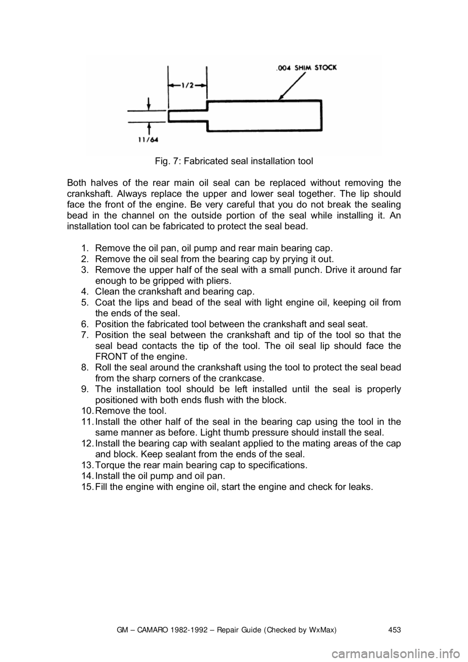
Fig. 7: Fabricated s eal installation tool
Both halves of the rear main oil s eal can be replaced without removing the
crankshaft. Always replace the upper and lower seal together. The lip should
face the front of the engine. Be very ca reful that you do not break the sealing
bead in the channel on the out side portion of the seal while installing it. An
installation tool can be fabricat ed to protect the seal bead.
1. Remove the oil pan, oil pump and rear main bearing cap.
2. Remove the oil seal from the bearing cap by prying it out.
3. Remove the upper half of the seal wit h a small punch. Drive it around far
enough to be gripped with pliers.
4. Clean the crankshaft and bearing cap.
5. Coat the lips and bead of the seal with light engine oil, keeping oil from
the ends of the seal.
6. Position the fabricated tool bet ween the crankshaft and seal seat.
7. Position the seal between the cranks haft and tip of the tool so that the
seal bead contacts the ti p of the tool. The oil seal lip should face the
FRONT of the engine.
8. Roll the seal around the crankshaft us ing the tool to protect the seal bead
from the sharp corner s of the crankcase.
9. The installation tool should be le ft installed until the seal is properly
positioned with both ends fl ush with the block.
10. Remove the tool.
11. Install the other half of the seal in the bearing cap using the tool in the
same manner as before. Light thumb pressure should install the seal.
12. Install the bearing cap with sealant applied to the mating areas of the cap
and block. Keep sealant from the ends of the seal.
13. Torque the rear main bear ing cap to specifications.
14. Install the oil pump and oil pan.
15. Fill the engine with engine oil, st art the engine and check for leaks.
Page 456 of 875

GM – CAMARO 1982-1992 – Repair Guide (Checked by WxMax) 456
2. Drain the engine oil and remove the oil pan.
3. Remove the rear main bearing cap.
4. Insert packing tool J-29114-2 or equi
valent, against 1 end of the seal in
the cylinder block. Drive the old seal gently into the groove until it is
packed tight. This will vary from
1/4 in. (6mm) to 3/4 in. (19mm) depending
on the amount of pack required.
5. Repeat the procedure on t he other end of the seal.
6. Measure the amount the seal wa s driven up on one side and add
1/16 in.
(1.6mm). Using a suitable cutting tool, cut that length from the old seal
removed from the rear main beari ng cap. Repeat the procedure for the
other side. Use the rear main bear ing cap as a holding fixture when
cutting the seal.
7. Install guide tool J-29114-1 or equi valent, onto the cylinder block.
8. Using the packing tool, work the shor t pieces cut in Step 6 into the guide
tool and then pack into the cylinder block. The guide tool and packing
tool are machined to provide a built in stop. Use this procedure for both
sides. It may help to use oil on the short pieces of the rope seal when \
packing them into the cylinder block.
9. Remove the guide tool.
10. Apply Loctite® 414 or equivalent, to the seal groove in the rear main
bearing cap. Within 1 minute, insert a new seal into the groove and push
into place with tool J-29590 until the seal is flush with the block. Cut the
excess seal material with a sharp cu tting tool at the bearing cap parting
line.
11. Apply a thin film of chassis grease to the rope se al. Apply a thin film of
RTV sealant on the bearing cap mati ng surface around the seal groove.
Use the sealer sparingly.
12. Plastigage® the rear main bea ring cap as outlined in MEASURING
REAR MAIN CLEARANCE in this section and check with specification. If
out of specification, check for fr ying of the rope seal which may be
causing the cap to not seat properly.
13. Install all remaining com ponents and inspect for leaks.
FLYWHEEL AND RING GEAR
REMOVAL & INSTALLATION
The ring gear is an integral part of the flywheel and is not replaceable.
1. Remove the transmission.
2. Remove the six bolts attaching t he flywheel to the crankshaft flange.
Remove the flywheel.
3. Inspect the flywheel for cracks, and inspect the ring gear for burrs or
worn teeth. Replace the flywheel if any damage is apparent. Remove
burrs with a mill file.
4. Install the flywheel. Th e flywheel will only attach to the crankshaft in one
position, as the bolt holes are unevenly spaced. Install the bolts and
torque to specification. Tighten bolts in crisscross pattern.
Page 499 of 875

GM – CAMARO 1982-1992 – Repair Guide (Checked by WxMax) 499
then you have wrist pin bushings in the rods. There should not be any
excessive play between the wrist pin
and the rod bushing. Normal clearance for
the wrist pin is approx. 0.001-0.002 in. (0.025mm-0.051mm).
Fig. 4: Measure the piston's outer diam eter, perpendicular to the wrist pin, with
a micrometer
Use a micrometer and measure the diamet er of the piston, perpendicular to the
wrist pin, on the skirt. Com pare the reading to its original cylinder measurement
obtained earlier. The diffe rence between the two readings is the piston-to-wall
clearance. If the clearance is within specif ications, the piston may be used as is.
If the piston is out of specification, but the bore is not, you will need a new
piston. If both are out of specificati on, you will need the cylinder rebored and
oversize pistons installed. Generally if two or more pistons/bores are out of
specification, it is best to rebore the entire block and purchase a complete set of
oversize pistons.
CONNECTING ROD
You should have the connecting rod chec ked for straightness at a machine
shop. If the connecting rod is bent, it will unevenly wear the bearing and piston,
as well as place greater stress on these components. Any bent or twisted
connecting rods must be replaced. If the rods are straight and the wrist pin
clearance is within specifications, t hen only the bearing end of the rod need be
checked. Place the connecting rod into a vi ce, with the bearing inserts in place,
install the cap to the rod and torque t he fasteners to specifications. Use a
telescoping gauge and carefully measure t he inside diameter of the bearings.
Compare this reading to the rods or iginal crankshaft journal diameter
measurement. The difference is the oil clearance. If the oil clearance is not
Page 504 of 875

GM – CAMARO 1982-1992 – Repair Guide (Checked by WxMax) 504
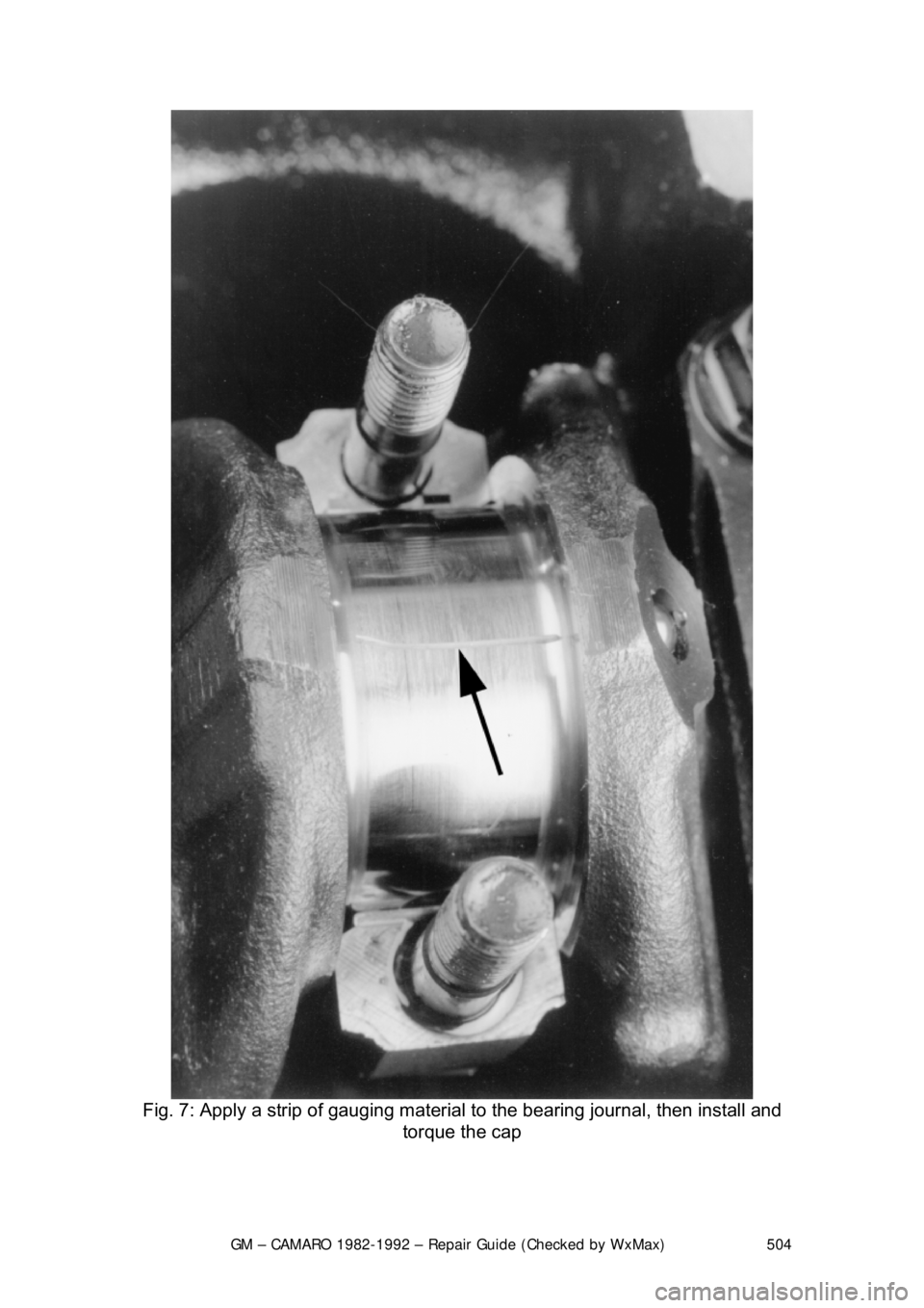
Fig. 7: Apply a strip of gauging material to the bearing journal, then install and
torque the cap
Page 556 of 875

GM – CAMARO 1982-1992 – Repair Guide (Checked by WxMax) 556
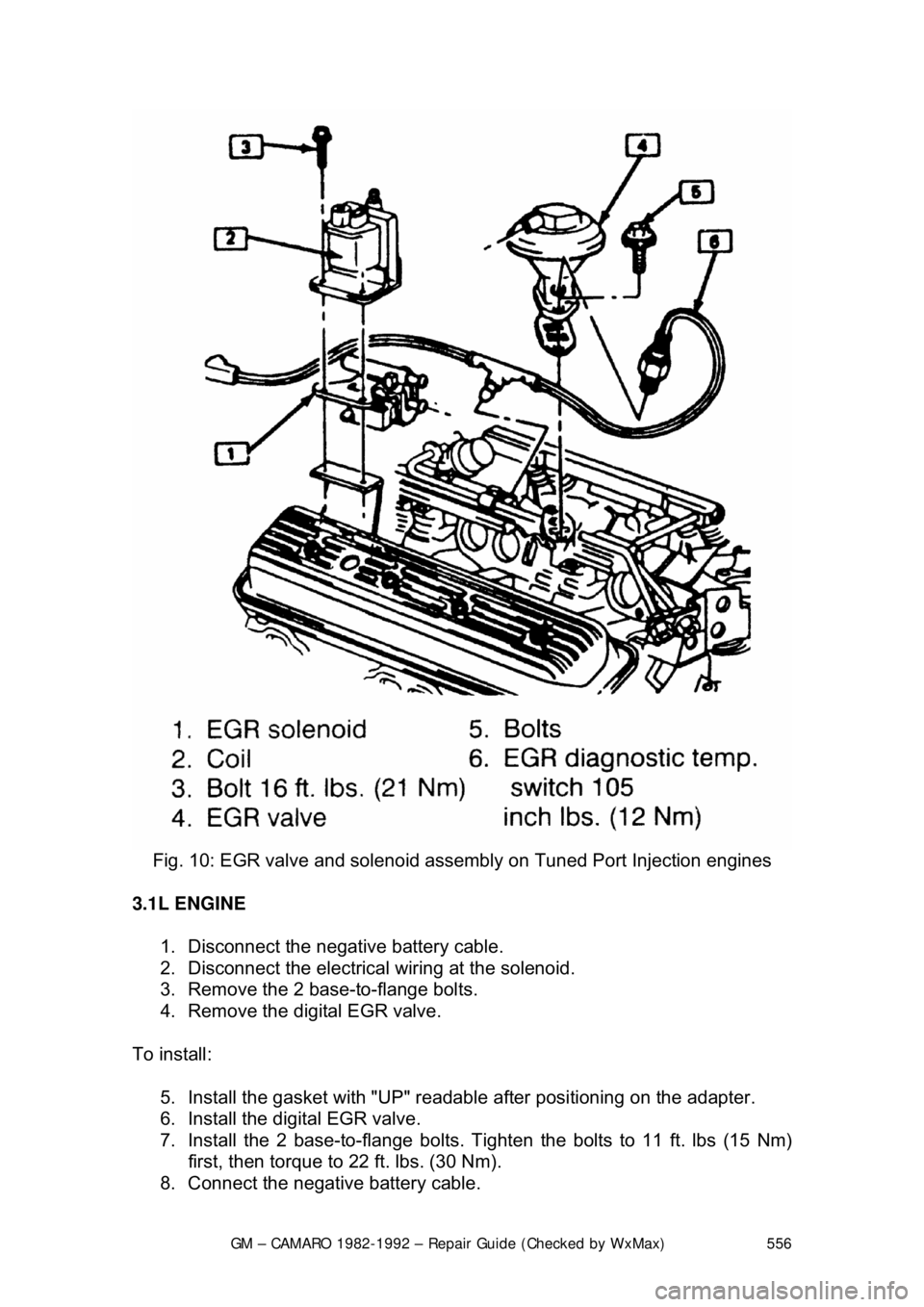
Fig. 10: EGR valve and solenoid a ssembly on Tuned Port Injection engines
3.1L ENGINE 1. Disconnect the negative battery cable.
2. Disconnect the electrical wiring at the solenoid.
3. Remove the 2 base-to-flange bolts.
4. Remove the digital EGR valve.
To install: 5. Install the gasket with "UP" readabl e after positioning on the adapter.
6. Install the digital EGR valve.
7. Install the 2 base-to-f lange bolts. Tighten the bolts to 11 ft. lbs (15 Nm)
first, then torque to 22 ft. lbs. (30 Nm).
8. Connect the negative battery cable.
Page 580 of 875

GM – CAMARO 1982-1992 – Repair Guide (Checked by WxMax) 580
4. Spray a commercial solvent onto the sensor threads and allow it to soak
in for at least five minutes.
5. Carefully remove the sensor wit h a special oxygen sensor socket.
To install: 6. First coat the new sensor's th reads with GM anti-seize compound No.
5613695 or the equivalent. This is not a conventional anti-seize paste.
The use of a regular compound may el ectrically insulate the sensor,
rendering it inoperative. Y ou must coat the threads with an electrically
conductive anti-seize compound. Installati on torque is 30 ft. lbs. (41 Nm).
Do not overtighten.
7. Reconnect the electric al wiring. Be careful not to damage the electrical
pigtail. Check the sensor boot fo r proper fit and installation.
8. Reconnect the negative battery cable.
COOLANT TEMPERATURE SENSOR
OPERATION
Most engine functions are affected by the coolant temperature. Determining
whether the engine is hot or cold is largely dependent on the temperature of the
coolant. An accurate temperature signal to the ECM is supplied by the coolant
temperature sensor. The coolant temperatur e sensor is a thermistor mounted in
the engine coolant stream. A thermistor is an electrical device that varies its
resistance in relation to changes in temperature. Low coolant temperature
produces a high resistance and high coolant temperature produces low
resistance. The ECM supplies a signal of 5 volts to the coolant temperature
sensor through a resistor in the ECM and measures the voltage. The voltage
will be high when the engine is cold and low when the engine is hot.
REMOVAL & INSTALLATION
1. Disconnect the negative battery cable.
2. Drain the cooling system to an appropr iate and clean container for reuse.
3. Disconnect the electrical wiring fr om the coolant temperature sensor.
4. Remove the coolant temperature sensor.
To install: 5. Install the coolant temperature sensor.
6. Connect the electrical wiring.
7. Fill the cooling system.
8. Connect the negative battery cable.
9. Start the engine and check for leaks.
Page 669 of 875

GM – CAMARO 1982-1992 – Repair Guide (Checked by WxMax) 669
1. Disconnect the pressure gauge. R
un the fuel line into a graduated
container.
2. Run the engine at idle until one pint of gasoline has been pumped. One
pint should be delivered in 30 seconds or less. There is normally enough
fuel in the carburetor float bowl to perform this test, but refill it if
necessary.
3. If the delivery rate is below the mini mum, check the lines for restrictions
or leaks, then r eplace the pump.
CARBURETORS
The V6 engine is equipped with the Ro chester E2SE carburetor, V8 engines
use the E4ME and E4MC. These carburet ors are of the downdraft design and
are used in conjunction with the CCC system for fuel cont rol. They have special
design features for optimum air/fuel mixt ure control during all ranges of engine
operation.
An electric solenoid in the carburetor controls the air/fu el ratio. The solenoid is
connected to an Electronic Control Module (ECM) which is an on-board
computer. The ECM provides a controllin g signal to the solenoid. The solenoid
controls the metering rod(s) and an id le air bleed valve, thereby closely
controlling the air/fuel ratio throughout the operating range of the engine.
MODEL IDENTIFICATION
General Motors Rochester carburetors ar e identified by their model code. The
first number indicates the number of ba rrels, while one of the last letters
indicates the type of choke used. These are V for the manifold mounted choke
coil, C for the choke coil mounted in the carburetor body, and E for electric
choke, also mounted on the carburetor. Model codes ending in A indicate an
altitude-compensatin g carburetor.
Because of their intricate nature and co mputer controls, the E2SE, E4ME and
E4MC carburetors should only be se rviced by a qualified technician.
PRELIMINARY CHECKS
The following should be observed befor e attempting any adjustments.
1. Thoroughly warm the engine. If the engine is cold, be sure that it reaches
operating temperature.
2. Check the torque of all carburet or mounting nuts and assembly screws.
Also check the intake manifold-to-cyli nder head bolts. If air is leaking at
any of these points, any attempts at adjustment will inevitably lead to
frustration.
3. Check the manifold heat control valve (if used) to be sure that it is free.
4. Check and adjust the choke as necessary.
5. Adjust the idle speed and mixture. If the mixture screws are capped,
don't adjust them unless all other c auses of rough idle have been
eliminated. If any adjustments are per formed that might possibly change
Page 701 of 875

GM – CAMARO 1982-1992 – Repair Guide (Checked by WxMax) 701
Fig. 32: Throttle position sensor adjusting screw location on E4ME/E4MC
carburetors
REMOVAL & INSTALLATION
Always replace all internal gaskets that are removed. Flooding, stumble on
acceleration and other performance comp laints are in many instances, caused
by presence of dirt, water, or other foreign matter in carburetor. To aid in
diagnosis, carburetor should be carefully removed from engine without draining
fuel from bowl. Contents of fuel bowl may then be examined for contamination
as carburetor is disassembl ed. Check the fuel filter.
ROCHESTER E2SE 1. Remove air cleaner and gasket.
2. Disconnect fuel pipe and vacuum lines.
3. Disconnect electrical connectors.
4. Disconnect accelerator linkage.
5. If equipped with automatic transmi ssion, disconnect downshift cable.
6. If equipped with cruise c ontrol, disconnect linkage.
7. Remove carburetor attaching bolts.
8. Remove carburetor and EF E heater/insulator (if used).
9. Inspect EFE heater/insulator for damage. Be certain throttle body and
EFE heater/insulator surfaces are clean.
To install: 10. Install EFE heater/insulator.
11. Install carburetor and tighten nuts alternately to the correct torque.
12. Connect downshift cable, as required.
13. Attach the cruise cont rol cable, as required.
14. Connect accelerator linkage.
15. Connect electrical connections.