1973 DATSUN B110 brake fluid
[x] Cancel search: brake fluidPage 208 of 513

BODY
Fig
BF
29
Removing
front
fender
II
FRONT
BUMPER
Remove
six
bolts
retaining
bumper
stay
to
body
and
remove
the
front
bumper
from
the
body
together
with
the
bumper
stay
RADIATOR
GRILLE
Loosen
self
tapping
screws
five
self
tapping
screws
for
sedan
station
wagon
and
van
and
ten
for
coupe
and
remove
the
radiator
grille
frorn
the
body
The
radiator
grille
for
coupe
is
made
of
ABS
resin
Be
careful
not
to
allow
brake
fluid
or
oil
slicking
to
it
7
7f
rl4
o
j
j
iiA
i
DIATIJR
GR
L
SEt
SC
8N
S
i
e
t
II
L
T
RADIATOR
GRill
SET
SCREWS
Fig
BF
30
Removing
radiator
grille
Coupe
OUTSIDE
MIRROR
Indicates
outside
mirror
installing
positions
liMA
t
o
e
O
I
I
Dimen
sIons
Item
A
B
c
D
E
27
to
6
to
Round
shape
817
29
5
25
27
8
dia
6
2
dia
movable
32
2
1
161
0
98431
1
063
to
0
2362
te
mirror
1
094
0
2441
6
to
Round
shape
817
35
40
9
dia
6
2
dia
mirror
32
2
1
378
l
575
0
3543
0
2362
to
0
2441
Unit
mm
in
Fig
BF
31
Fender
mirror
installing
positions
IW
36
l
71
Ta
h
Le
O
II
coo
c
l
2
f
4
5
358
17
77
74
7
Unit
mm
inl
Fig
RF
32
Door
mirror
installing
position
for
right
hand
drive
vehicle
SF
18
Page 228 of 513
@
c
@
CD
w
1
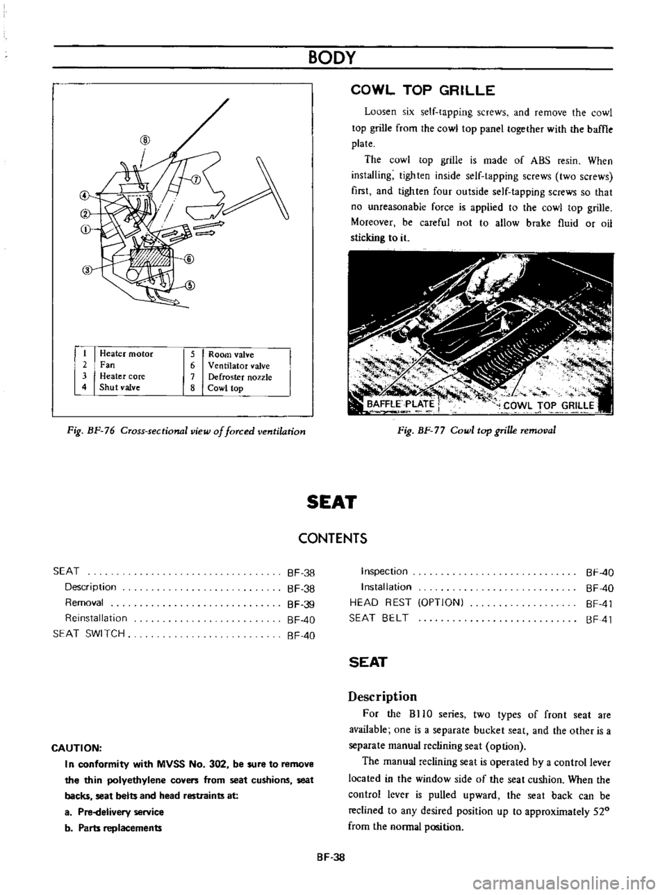
Heater
motor
2
Fan
3
Heater
core
4
Shut
valve
5
Room
valve
6
Ventilator
valve
7
Defroster
nozzle
8
Cowl
top
Fig
BF
76
Cross
sectional
view
of
forced
ventilation
BODY
COWL
TOP
GRILLE
Loosen
six
self
tapping
screws
and
remove
the
cowl
top
grille
from
the
cowl
top
panel
together
with
the
baffle
plate
The
cowl
top
grille
is
made
of
ABS
resin
When
installing
tighten
inside
self
tapping
screws
two
screws
first
and
lighten
four
outside
self
tapping
screws
so
that
no
unreasonable
force
is
applied
to
the
cowl
top
grille
Moreover
be
careful
not
to
allow
brake
fluid
or
oil
sticking
to
it
Fig
BF
77
Cowl
top
grille
removal
SEAT
CONTENTS
SEAT
Description
Removal
Reinstallation
SEAT
SWI
TCH
BF
38
BF
38
BF
39
BF
40
BF
40
CAUTION
I
n
conformity
with
MVSS
No
302
be
sure
to
remove
the
thin
polyethylene
covers
from
seat
cushions
seat
backs
seat
belts
and
head
restraints
at
a
Pi
Helivery
service
b
Parts
replacements
Inspection
Installation
HEAD
REST
OPTIONI
SEAT
BELT
BF
40
BF
40
BF
41
BF
41
SEAT
Description
For
the
BHO
series
two
types
of
front
seat
are
available
one
is
a
separate
bucket
seat
and
the
other
is
a
separate
manual
reclining
seat
option
The
manual
reclining
seat
is
operated
by
a
control
lever
located
in
the
window
side
of
the
seat
cushion
When
the
control
lever
is
pulled
upward
the
seat
back
can
be
reclined
to
any
desired
position
up
to
approximately
520
from
the
normal
position
BF
38
Page 302 of 513
GENERAL
INFORMATION
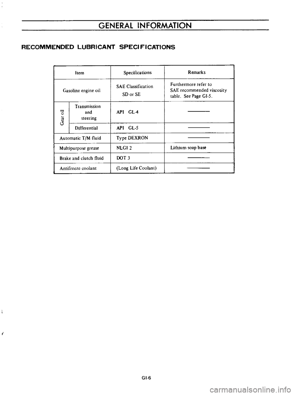
RECOMMENDED
LUBRICANT
SPECI
FICATIONS
Item
Gasoline
engine
oil
o
Transmission
and
steering
Differential
Automatic
TIM
fluid
Multipurpose
grease
Brake
and
clutch
fluid
Antifreeze
coolant
i
Specifications
SAE
Classification
SO
or
SE
API
G
L
4
API
GL
5
Type
DEXRON
NLGI2
DOT
3
Long
Life
Coolant
GI
6
Remarks
Furthermore
refer
to
SAE
recommended
viscosity
table
See
Page
GI
5
Lithium
soap
base
Page 479 of 513
CLUTCH
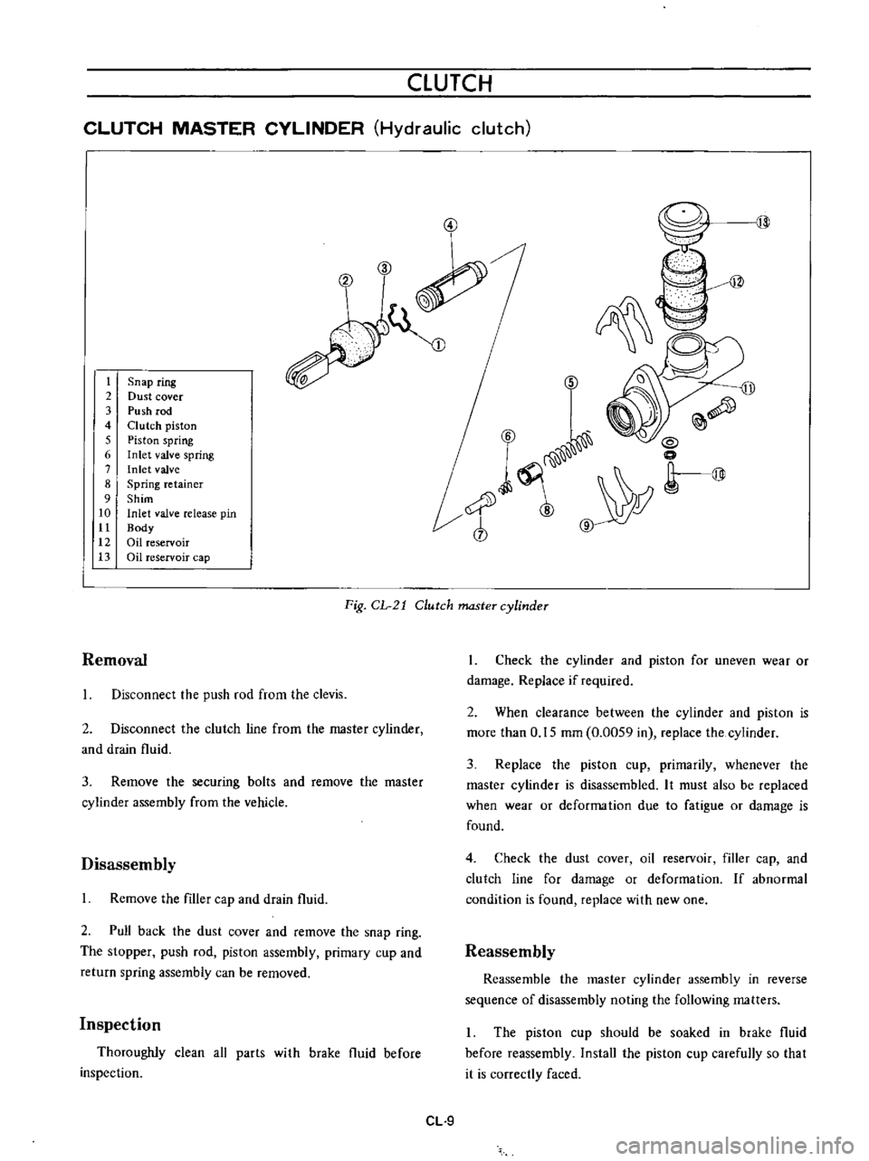
CLUTCH
MASTER
CYLINDER
Hydraulic
clutch
3
V
t
2
3
4
5
6
7
8
9
10
tt
12
13
Snap
ring
Dust
cover
Push
rod
Clutch
piston
Piston
spring
Inlet
valve
spring
Inlet
valve
Spring
retainer
Shim
Inlet
valve
release
pin
Body
Oil
reservoir
Oil
reservoir
cap
6
D
ll
Q
6
i
0
l
Y
r@
cb
Fig
CL
21
Clutch
master
cylinder
Removal
Disconnect
the
push
rod
from
the
clevis
2
Disconnect
the
clutch
line
from
the
master
cylinder
and
drain
fluid
3
Remove
the
securing
bolts
and
remove
the
master
cylinder
assembly
from
the
vehicle
Disassembly
Remove
the
filler
cap
and
drain
fluid
2
Pull
back
the
dust
cover
and
remove
the
snap
ring
The
stopper
push
rod
piston
assembly
primary
cup
and
return
spring
assembly
can
be
removed
Inspection
Thoroughly
clean
all
parts
with
brake
fluid
before
inspection
CL
9
1
Check
the
cylinder
and
piston
for
uneven
wear
or
damage
Replace
if
required
2
When
clearance
between
the
cylinder
and
piston
is
more
than
0
15
mm
0
0059
in
replace
the
cylinder
3
Replace
the
piston
cup
primarily
whenever
the
master
cylinder
is
disassembled
It
must
also
be
replaced
when
wear
or
deforma
tion
due
to
fatigue
or
damage
is
found
4
Check
the
dust
cover
oil
reservoir
filler
cap
and
clutch
line
for
damage
or
deformation
If
abnormal
condition
is
found
replace
with
new
one
Reassembly
Reassemble
the
master
cylinder
assembly
in
reverse
sequence
of
disassembly
noting
the
following
matters
The
piston
cup
should
be
soaked
in
brake
fluid
before
reassembly
Install
the
piston
cup
carefully
so
that
it
is
correctly
faced
Page 480 of 513
CHASSIS
2
Apply
brake
fluid
sufficiently
to
the
cylinder
and
piston
and
assemble
them
Reinstallation
Reinstall
the
master
cylinder
assembly
in
reverse
sequence
of
removal
and
adjust
as
follows
I
Adjust
the
pedal
height
by
changing
the
push
rod
length
2
B
eed
air
out
of
the
hydraulic
system
OPERATING
CYLINDER
Hydraulic
clutch
Removal
Remove
the
return
spring
2
Disconnect
the
clutch
line
from
the
operating
cyl
inder
3
Disconnect
the
push
rod
from
the
withdrawal
lever
4
Release
two
bolts
used
to
mount
the
operating
cylinder
to
the
clutch
housing
Disassembly
1
Remove
the
dust
cover
2
Remove
the
snap
ring
and
all
other
parts
can
be
disassembled
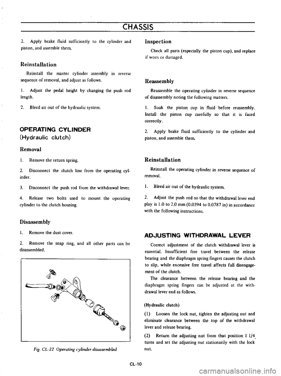
@
Fig
CL
22
Operating
cylinder
disassembled
CL
10
Inspection
Check
all
parts
especially
the
piston
cup
and
replace
if
worn
or
damaged
Reassembly
Reassemble
the
operating
cylinder
in
reverse
sequence
of
disassembly
noting
the
following
matters
Soak
the
piston
cup
in
fluid
before
reassembly
Install
the
piston
cup
carefully
so
that
it
is
faced
correctly
2
Apply
brake
fluid
sufficiently
to
the
cylinder
and
piston
and
assemble
them
Reinstallation
Reinstal
the
operating
cylinder
in
reverse
sequence
of
removal
1
Bleed
air
out
of
the
hydraulic
system
2
Adjust
the
push
rod
so
that
the
withdrawal
lever
end
play
is
0
to
2
0
mm
0
0394
to
0
0787
in
in
accordance
with
the
following
instructions
AD
USTING
WITHDRAWAL
LEVER
Correct
adjustment
of
the
clutch
withdrawal
lever
is
essential
Insufficient
free
travel
between
the
release
bearing
and
the
diaphragm
spring
fingers
causes
the
clutch
to
slip
while
excessive
free
travel
affects
full
disengage
ment
of
the
clutch
The
clearance
between
the
release
bearing
and
the
diaphragm
spring
fingers
can
be
adjusted
at
the
with
drawallever
end
as
follows
Hydraulic
clutch
Loosen
the
lock
nut
tighten
the
adjusting
nut
and
eliminate
clearance
between
the
top
of
the
withdrawal
lever
and
release
bearing
2
Return
the
adjusting
nut
from
that
position
I
4
turns
and
set
the
adjusting
nut
stationarily
with
the
lock
nut
Page 481 of 513
CLUTCH
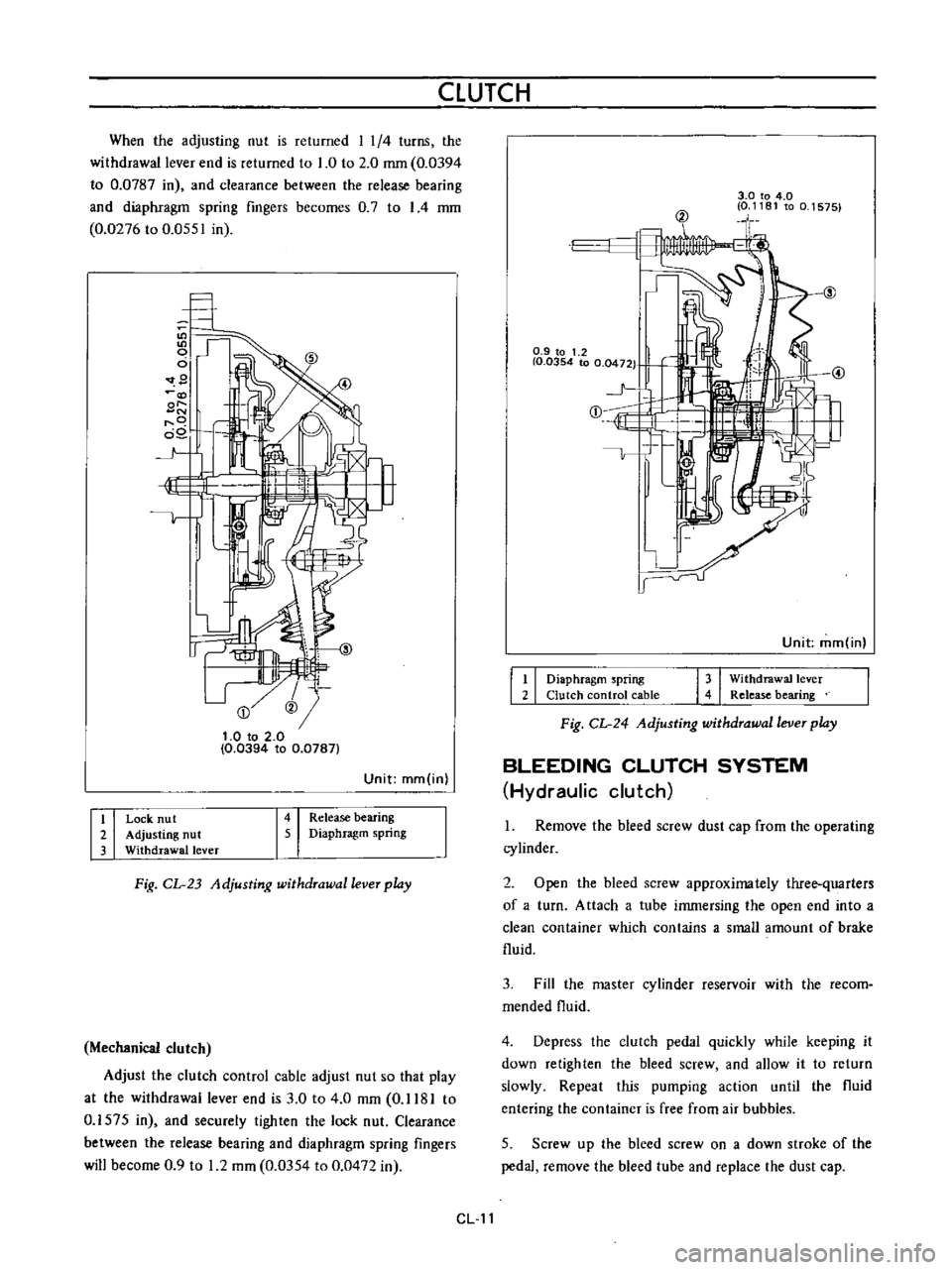
When
the
adjusting
nut
is
returned
I
1
4
turns
the
withdrawal
lever
end
is
returned
to
1
0
to
2
0
mm
0
0394
to
0
0787
in
and
clearance
between
the
release
bearing
and
diaphragm
spring
fingers
becomes
0
7
to
I
4
mm
0
0276
to
0
0551
in
9
@
t
O
to
2
0
0
0394
to
0
0787
Unit
mm
in
I
i
I
I
I
Release
bearing
Diaphragm
spring
Lock
nu
t
Adjusting
nut
Withdrawal
lever
Fig
CL
23
Adjusting
withdrawal
lever
play
Mechanical
clutch
Adjust
the
clutch
control
cable
adjust
nut
so
that
play
at
the
withdrawal
lever
end
is
3
0
to
4
0
mm
0
1181
to
0
1575
in
and
securely
tighten
the
lock
nut
Clearance
between
the
release
bearing
and
diaphragm
spring
fingers
will
become
0
9
to
1
2
mm
0
0354
to
0
0472
in
3
0
to
4
0
0
1181
to
0
1575
@
0
9
to
1
2
I
0
0354
to
0
0472
1
j
E
1
Unit
mm
in
I
I
I
I
Diaphragm
spring
Clutch
control
cable
Withdrawal
lever
Release
bearing
Fig
CL
24
Adjusting
withdrawal
lever
play
BLEEDING
CLUTCH
SYSTEM
Hydraulic
clutch
1
Remove
the
bleed
screw
dust
cap
from
the
operating
cylinder
2
Open
the
bleed
screw
approximately
three
quarters
of
a
turn
Attach
a
tube
immersing
the
open
end
into
a
clean
container
which
contains
a
small
amount
of
brake
fluid
3
Fill
the
master
cylinder
reservoir
with
the
recom
mended
fluid
4
Depress
the
clutch
pedal
quickly
while
keeping
it
down
retighten
the
bleed
screw
and
allow
it
to
return
slowly
Repeat
this
pumping
action
until
the
fluid
entering
the
container
is
free
from
air
bubbles
5
Screw
up
the
bleed
screw
on
a
down
stroke
of
the
pedal
remove
the
bleed
tube
and
replace
the
dust
cap
CL
11
Page 484 of 513
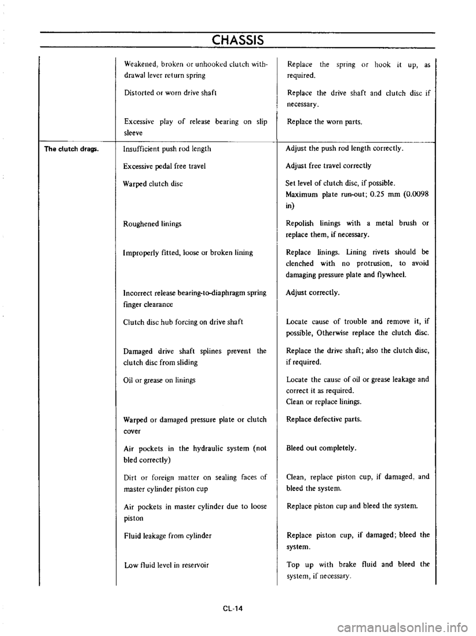
The
clutch
drags
CHASSIS
Weakened
broken
ur
unhooked
clutch
with
drawallever
return
spring
Distorted
or
worn
drive
shaft
Excessive
play
of
release
bearing
on
slip
sleeve
Insufficient
push
rod
length
Excessive
pedal
free
travel
Warped
clutch
disc
Roughened
linings
Improperly
fitted
loose
or
broken
lining
Incorrect
release
bearing
to
diaphragm
spring
fmger
clearance
Clutch
disc
hub
forcing
on
drive
shaft
Damaged
drive
shaft
splines
prevent
the
clutch
disc
from
sliding
Oil
or
grease
on
linings
Warped
or
damaged
pressure
plate
or
clutch
cover
Air
pockets
in
the
hydraulic
system
not
bled
correctly
Dirt
or
foreign
matter
on
sealing
faces
of
master
cylinder
piston
cup
Air
pockets
in
master
cylinder
due
to
loose
piston
Fluid
leakage
from
cylinder
Low
fluid
level
in
reservoir
CL14
Replace
the
spring
or
hook
it
up
as
required
Replace
the
drive
shaft
and
clutch
disc
if
necessary
Replace
the
worn
parts
Adjust
the
push
rod
length
correctly
Adjust
free
travel
correctly
Set
level
of
clutch
disc
if
possible
Maximum
plate
run
out
0
25
mm
0
0098
in
Repolish
linings
with
a
metal
brush
or
replace
them
if
necessary
Replace
linings
Lining
rivets
should
be
clenched
with
no
protrusion
to
avoid
damaging
pressure
plate
and
flywheel
Adjust
correctly
Locate
cause
of
trouble
and
remove
it
if
possible
Otherwise
replace
the
clutch
disc
Replace
the
drive
shaft
also
the
clutch
disc
if
required
Locate
the
cause
of
oil
or
grease
leakage
and
correct
it
as
required
Clean
or
replace
linings
Replace
defective
parts
Bleed
out
completely
Clean
replace
piston
cup
if
damaged
and
bleed
the
system
Replace
piston
cup
and
bleed
the
system
Replace
piston
cup
if
damaged
bleed
the
system
Top
up
with
brake
fluid
and
bleed
the
system
if
necessary