Page 282 of 513
Tool
number
Tool
name
ST30600000
Drive
pinion
bearing
drift
ST31121000
Heigh
t
gauge
ST31122000
Dummy
shaft
ST3154llllUll
Drive
pinion
flange
wrench
ST3250S000
Side
bearing
adjust
weight
SERVICE
EQUIPMENT
Figure
mm
inch
15516
101
36114171dia
31
1
220
dia
70
2
756
cHa
r
84
513
271
20
O
Je7l
diil
L
9I17510Y
sE
lO
Description
For
installing
the
drive
pinion
rear
bearing
inner
race
For
height
adjustment
of
the
drive
pinion
For
height
adjustment
of
the
drive
pinion
For
removal
of
the
dri
ve
pinion
nut
For
determining
the
side
bearing
adjust
shim
S
M
reference
page
See
Fig
No
Page
PD
II
Fig
PD
22
Fig
PD
23
Fig
PD
22
Fig
PD
23
Fig
PD
12
Fig
PD
25
Page 368 of 513

ENGINE
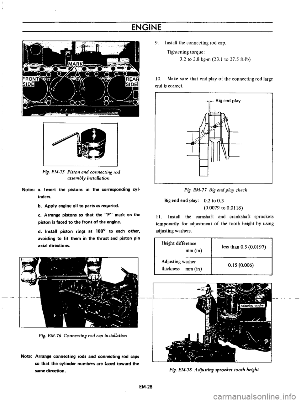
Fig
EM
75
Piston
and
connecting
rod
assembly
installation
Notes
8
I
nsert
the
pistons
in
the
corresponding
cyl
inders
b
Apply
engine
oil
to
parts
as
requried
c
Arrange
pistons
so
that
the
F
mark
on
the
piston
is
faced
to
the
front
of
the
engine
d
Install
piston
rings
at
180
to
each
other
avoiding
to
fit
them
in
the
thrust
and
piston
pin
axial
directions
Fig
EM
76
Connecting
rod
cap
installation
Note
Arrange
connecting
rods
and
connecting
rod
caps
so
that
the
cylinder
numbers
are
faced
toward
the
same
direction
EM
28
q
Install
the
connecting
rod
cap
Tightening
torque
32
to
3
8
kg
m
23
I
to
7
S
ft
lb
10
Make
sure
that
end
play
of
the
connecting
rod
large
end
is
correct
Big
end
play
j
I
Fig
EM
77
Big
end
play
check
Big
end
end
play
0
2
to
0
3
0
0079
to
0
0118
11
Install
the
camshaft
and
crankshaft
sprockets
temporarily
for
adjustment
of
the
tooth
height
by
using
adjusting
washers
Height
difference
mm
in
less
than
O
S
0
0197
Adjusting
washer
thickness
mm
in
O
IS
0
006
Fig
EM
78
Adjusting
sprocket
tooth
height
Page 476 of 513

CHASSIS
fulcrum
type
The
mechanical
type
clutch
control
system
consists
of
pendent
clutch
pedal
clutch
control
cable
and
with
drawallever
The
withdrawal
lever
is
of
an
outer
fulcrum
type
which
provides
a
great
lever
ratio
and
thus
force
required
in
depressing
clutch
pedal
is
reduced
CLUTCH
PEDAL
Hydraulic
clutch
Removal
Remove
the
return
spring
2
Loosen
the
lock
nut
of
the
master
cylinder
push
rod
and
disconnect
the
push
rod
end
3
Remove
the
lock
nut
and
washer
of
the
pedal
shaft
and
remove
the
pedal
lever
Inspection
Thoroughly
clean
all
disassembled
parts
indicated
below
and
carefully
check
them
for
wear
damage
and
other
abnormal
conditions
Repair
or
replace
them
with
new
ones
if
required
f
fS
C5
J
dJ
YII
10
1
@
c
i
@
j
1
4
K
Clutch
pedal
free
trrlel
30
mm
1
181
nl
00
@
P
IO
Pedal
head
rubber
2
Return
spring
3
Pedal
lever
bush
4
Fulcrum
pedal
pin
etc
Reinstallation
Reinstall
the
clutch
pedal
in
reverse
sequence
of
removal
Adjustment
I
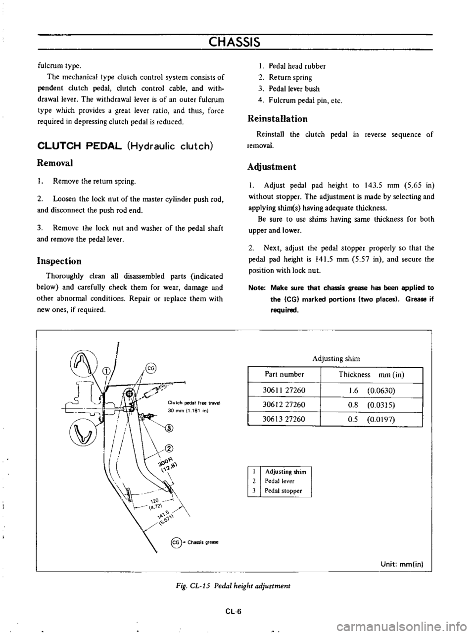
Adjust
pedal
pad
height
to
143
5
mm
5
65
in
without
stopper
The
adjustment
is
made
by
selecting
and
applying
shim
s
having
adequate
thickness
Be
sure
to
use
shims
having
same
thickness
for
both
upper
and
lower
2
Next
adjust
the
pedal
stopper
properly
so
that
the
pedal
pad
height
is
141
5
mm
5
57
in
and
secure
the
position
with
lock
nut
Note
Make
sure
that
chassis
grease
has
been
applied
to
the
leG
marked
portions
two
places
Grease
if
required
Adjusting
shim
Part
number
Thickness
mm
in
30611
27260
30612
27260
30613
27260
1
6
0
0630
0
8
0
0315
0
5
0
0197
I
2
3
Adjusting
shim
Pedal
lever
Pedal
stopper
Unit
mm
inl
Fig
CL
J5
Pedal
height
adjustment
CL
6
Page 478 of 513
CHASSIS
i
I
I
I
II
I
I
J
u
IlllrP
Zll
I
ff
Pedal
play
11
to
15
I
0
433
to
0
591
I
W
p
da
stfO
l
e
1
P
point
end
play
l
e
A
1
C
3
0
to
A
O
Chassis
grease
20
0
1181
to
0
1575
I
Y
136
5
to
lA6
5
I
5
A
to
5
81
0
Note
Connect
the
control
cable
correctly
so
that
mark
cap
is
faced
upward
as
shown
in
the
following
figure
Make
sure
that
chassis
grease
has
been
I
2
3
Lock
nu
t
Adjusting
nut
Pedal
stopper
applied
to
the
CG
marked
positions
three
places
Apply
grease
if
required
@
300R
t2
8J
Unit
mm
in
Fig
CL
19
Pedal
height
adjustment
3
When
the
clutch
pedal
is
heavy
remove
grease
filler
cap
from
front
portion
of
the
adjust
nut
and
grease
Be
sure
to
use
grease
containing
molybdenum
disulfide
Fig
CL
20
Greasing
to
the
nipple
of
clutch
control
cable
CL
8
Page 480 of 513

CHASSIS
2
Apply
brake
fluid
sufficiently
to
the
cylinder
and
piston
and
assemble
them
Reinstallation
Reinstall
the
master
cylinder
assembly
in
reverse
sequence
of
removal
and
adjust
as
follows
I
Adjust
the
pedal
height
by
changing
the
push
rod
length
2
B
eed
air
out
of
the
hydraulic
system
OPERATING
CYLINDER
Hydraulic
clutch
Removal
Remove
the
return
spring
2
Disconnect
the
clutch
line
from
the
operating
cyl
inder
3
Disconnect
the
push
rod
from
the
withdrawal
lever
4
Release
two
bolts
used
to
mount
the
operating
cylinder
to
the
clutch
housing
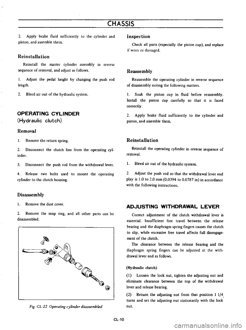
Disassembly
1
Remove
the
dust
cover
2
Remove
the
snap
ring
and
all
other
parts
can
be
disassembled
@
Fig
CL
22
Operating
cylinder
disassembled
CL
10
Inspection
Check
all
parts
especially
the
piston
cup
and
replace
if
worn
or
damaged
Reassembly
Reassemble
the
operating
cylinder
in
reverse
sequence
of
disassembly
noting
the
following
matters
Soak
the
piston
cup
in
fluid
before
reassembly
Install
the
piston
cup
carefully
so
that
it
is
faced
correctly
2
Apply
brake
fluid
sufficiently
to
the
cylinder
and
piston
and
assemble
them
Reinstallation
Reinstal
the
operating
cylinder
in
reverse
sequence
of
removal
1
Bleed
air
out
of
the
hydraulic
system
2
Adjust
the
push
rod
so
that
the
withdrawal
lever
end
play
is
0
to
2
0
mm
0
0394
to
0
0787
in
in
accordance
with
the
following
instructions
AD
USTING
WITHDRAWAL
LEVER
Correct
adjustment
of
the
clutch
withdrawal
lever
is
essential
Insufficient
free
travel
between
the
release
bearing
and
the
diaphragm
spring
fingers
causes
the
clutch
to
slip
while
excessive
free
travel
affects
full
disengage
ment
of
the
clutch
The
clearance
between
the
release
bearing
and
the
diaphragm
spring
fingers
can
be
adjusted
at
the
with
drawallever
end
as
follows
Hydraulic
clutch
Loosen
the
lock
nut
tighten
the
adjusting
nut
and
eliminate
clearance
between
the
top
of
the
withdrawal
lever
and
release
bearing
2
Return
the
adjusting
nut
from
that
position
I
4
turns
and
set
the
adjusting
nut
stationarily
with
the
lock
nut