1973 DATSUN B110 fuel cap
[x] Cancel search: fuel capPage 335 of 513

Air
intake
system
in
trouble
Overheating
Overcooling
Others
NOISY
ENGINE
Car
knocking
Car
knock
when
coasting
ENGINE
Diny
ur
clogged
fuel
strainer
Fuel
pump
will
not
work
properly
Clogged
carburetor
jets
Clogged
air
cleaner
Air
inhaling
from
manifold
gasket
or
carbu
retor
gasket
Insufficient
coolant
Loosened
fan
belt
Worn
or
defective
fan
belt
Defective
thermostat
Defective
water
pump
Clogged
or
leaky
radiator
Defective
radiator
filler
cap
Air
mixing
into
cooling
system
Improper
grade
engine
oil
Incorrect
ignition
timing
Defective
carburetor
lean
mixture
Defective
thermostat
Low
octane
fuel
Improper
tire
pressure
Dragging
brake
Slipping
clutch
Overloading
to
engine
Carbon
knocking
Timing
knocking
Fuel
knocking
Preignition
misusing
of
spark
plug
Incorrect
throttle
opener
adjustment
Trouble
in
PCV
valve
ET
30
Replace
Repair
or
replace
Disassemble
and
clean
Replace
element
Replace
gasket
Replenish
Adjust
Replace
Replace
Replace
Flush
repair
or
replace
Replace
Retighten
each
part
of
cooling
system
Replace
with
proper
grade
oil
Adjust
Overhaul
carburetor
Replace
Replace
with
specified
octane
fuel
Adjust
to
the
specified
pressure
Adjust
Adjust
Use
right
gear
in
driving
Disassemble
cylinder
head
and
remove
carbon
Adjust
ignition
timing
Use
specified
octane
fuel
Use
specified
spark
plug
Adjust
throttle
opener
Replace
PCV
valve
Page 372 of 513

ENGINE
27
Install
the
oil
pump
with
oil
filter
28
Install
the
alternator
fan
and
fan
belt
29
Install
the
fuel
pump
30
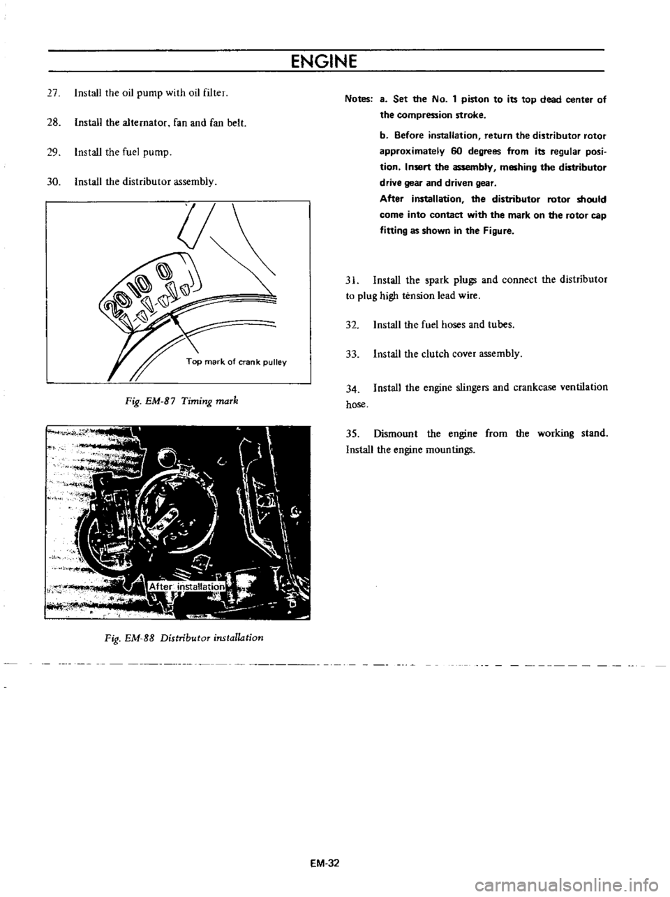
Install
the
distributor
assembly
Fig
EM
B7
Timing
maTk
Fig
EM
SS
Distributor
installation
EM
32
Notes
3
Set
the
No
1
piston
to
its
top
dead
center
of
the
compression
stroke
b
Before
installation
return
the
distributor
rotor
approximately
60
degrees
from
its
regular
posi
tion
Insert
the
assembly
meshing
the
distributor
drive
gear
and
driven
gear
After
installation
the
distributor
rotor
should
come
into
contact
with
the
mark
on
the
rotor
cap
fitting
as
shown
in
the
Figure
31
Install
the
spark
plugs
and
connect
the
distributor
to
plug
high
tension
lead
wire
32
Install
the
fuel
hoses
and
tubes
33
Install
the
clutch
cover
assembly
34
Install
the
engine
stingers
and
crankcase
ventilation
hose
35
Dismount
the
engine
from
the
working
stand
Install
the
engine
mountings
Page 396 of 513

FUEl
SYSTEM
FUEL
STRAINER
DESCRIPTION
The
fuel
strainer
is
of
a
cartridge
type
It
uses
paper
element
as
strainer
element
which
can
be
checked
for
condition
from
outside
This
strainer
cannot
be
cleaned
Replace
the
strainer
at
the
specified
service
interval
or
if
it
becomes
clogged
or
restricted
REMOVAL
Disconnect
inlet
and
outlet
fuel
lines
from
fuel
strainer
and
remove
fuel
strainer
Note
Before
disconnecting
fuel
lines
use
a
container
to
receive
the
remaining
fuel
in
lines
r
@
I
I
Il
QY
I
I
I
elementl
3
Cover
@
EF005
Fig
EF
10
Sectional
view
of
caTtridge
type
fuel
stTaineT
FUEL
PUMP
CONTENTS
DESCRIPTION
FUEL
PUMP
TESTING
Static
pressure
test
Capacity
test
EF
5
EF
6
EF
6
EF
6
DESCRIPTION
The
fuel
pump
transfers
gasoline
from
the
tank
to
the
carburetor
in
sufficient
quantity
to
meet
engine
require
ments
at
any
speed
or
load
The
fuel
pump
is
of
the
diaphragm
type
REMOVAL
AND
DISASSEMBLY
INSPECTION
ASSEMBLY
EF
7
EF
B
EF
B
The
fuel
pump
consists
of
a
body
rocker
arm
and
link
assembly
fuel
diaphragm
fuel
diaphragm
spring
seal
inlet
and
outlet
valves
The
fuel
diaphragm
consists
of
specially
treated
rubber
which
is
not
affected
by
gasoline
held
together
with
two
metal
discs
and
a
pull
rod
EF
5
Page 397 of 513

ENGINE
FUEL
PUMP
TESTING
A
fuel
pump
is
operating
properly
when
its
pressure
is
within
specifications
and
its
capacity
is
equal
to
the
engine
5
requirements
at
all
speeds
Pressure
and
cap
lcity
must
be
determined
by
two
tests
with
the
pump
mounted
on
the
engine
Be
sure
that
there
is
gasoline
in
the
tank
when
conducting
these
tests
Fig
EF
11
Schematic
view
of
fuel
pump
Static
pressure
test
The
static
pressure
test
is
conducted
as
follows
Disconnect
the
carburetor
fuel
line
at
the
carburetor
2
Install
the
necessary
adapter
and
tee
fitting
to
the
fuel
line
and
attach
a
suitable
pressure
gauge
Start
and
run
engine
at
varying
speeds
4
The
reading
on
the
gauge
is
the
static
fuel
pressure
and
this
should
remain
within
the
following
limits
0
18
kgJcm2
2
61b
sq
in
Pressure
below
the
lower
limit
indicates
extreme
wear
on
one
part
or
a
small
amount
of
wear
on
each
working
part
They
also
indicate
a
ruptured
diaphragm
worn
warped
dirty
or
gumming
valves
and
seats
or
weak
diaphragm
return
spring
Pressure
above
the
upper
limit
indicates
an
excessively
strong
diaphragm
that
is
too
tight
This
condition
requires
removal
of
the
fuel
pump
as
sembly
for
replacement
or
repair
Capacity
test
The
capacity
test
is
used
only
when
the
static
pressure
is
within
specifications
The
capacity
test
is
conducted
as
follows
1
Disconnect
the
fuel
pipe
at
the
carburetor
2
Place
a
suitable
container
at
the
end
of
the
pipe
3
Start
the
engine
and
run
at
1
000
rpm
4
The
pump
should
deliver
450
cc
I
V
S
p
of
fuel
in
one
minute
or
less
EF
6
Page 398 of 513

FUEL
SYSTEM
If
no
gasoline
or
only
a
little
flows
from
open
end
of
pipe
the
fuel
pipe
is
clogged
or
the
pump
is
malfunction
ing
Before
removing
the
pump
remove
the
gas
tank
cap
disconnect
both
inlet
and
outlet
pipes
and
blow
through
them
with
an
air
hose
to
make
sure
that
they
are
clear
This
will
eliminate
possible
clogged
gas
strainer
in
the
fuel
tank
Reconnect
the
pipes
to
the
pump
and
retest
flow
REMOVAL
AND
DISASSEMBLY
Remove
the
fuel
pump
assembly
by
unscrewing
two
mounting
nuts
and
disassemble
in
the
following
order
1
Separate
the
upper
body
and
the
lower
body
by
unscrewing
the
body
set
screws
2
Take
off
the
cap
and
the
cap
gasket
by
removing
the
cap
screw
3
Unscrew
the
elbow
and
the
connector
4
Take
off
the
valve
retainer
by
unscrewing
two
valve
retainer
screws
Two
valves
are
easily
removed
@
@
GS
5
To
remove
the
diaphragm
diaphragm
spring
lower
body
seal
washer
and
lower
body
seal
from
the
lower
body
press
down
the
diaphragm
counter
to
the
force
of
the
diaphragm
spring
and
while
doing
this
cant
the
diaphragm
so
that
the
rectangular
part
in
the
lower
end
of
the
pull
rod
is
unhooked
from
the
rocker
arm
link
Fig
EF
jJ
StructuTe
of
fuel
pump
EF
7
j
i
I
of
4
Fig
EF
12
Pull
Tad
Temoval
r1
r
f
i
t
1
2
3
4
5
6
7
B
9
10
tt
t2
t3
t4
15
t6
t7
tB
t9
20
2t
22
23
24
Valve
assem
bly
Packing
Retainer
Screw
Cap
Gasket
Screw
Washer
spring
Rocker
arm
Rocker
pin
Rocker
arm
spring
Spacer
Diaphragm
assembly
Retainer
Diaphragm
spring
Washer
spring
Nut
Washer
plain
Gasket
Spacer
Complete
body
lower
Connector
inlet
Connector
outlet
Page 416 of 513

FUEl
SYSTEM
EVAPORATIVE
EMISSION
CONTROL
SYSTEM
CONTENTS
OESCRI
PTION
Flow
guide
valve
MAINTENANCE
AND
TESTING
Checking
fuel
tank
vapor
liquid
separator
and
vapor
vent
I
ins
EF
25
EF
26
EF
26
EF
26
DESCRIPTION
This
system
consists
of
four
basic
elements
indicated
below
I
Fuel
tank
with
positive
sealing
filler
cap
with
relief
valve
2
Vapor
liquid
separator
3
Vapor
vent
line
4
Flow
guide
valve
The
flow
guide
valve
prevents
blow
by
gas
from
flowing
into
the
fuel
tank
and
guides
fresh
air
into
it
preventing
gasoline
vapor
from
escaping
into
the
carbure
tor
air
cleaner
Fl
me
ester
I
f
Flow
Thev
lve
opens
when
thlp
1l
rO
Inch
Hg
O
Positive
unk
venlI1atlon
PCV
hoe
Checking
fuel
tank
vacuum
relief
valve
operation
Checking
flow
guide
valve
EF
27
EF
27
Flow
guide
valve
operates
and
blow
by
gas
and
gasoline
vapor
flow
as
follows
When
the
engine
is
not
running
the
vapor
vent
line
vapor
liquid
separator
and
fuel
tank
are
filled
with
gasoline
vapor
produced
in
the
sealed
type
fuel
tank
A
flow
guide
valve
opens
when
the
gas
pressure
is
above
IOromHg
0
4
in
Hg
The
gas
passed
through
the
flow
guide
valve
2
is
accumulated
in
the
crankcase
Once
the
engine
starts
evaporates
in
the
crankcase
manifold
and
carburetor
air
cleaner
is
sucked
into
the
manifold
for
combustion
When
the
pressure
of
the
sealed
type
fuel
tank
vapor
liquid
separator
and
vapor
vent
line
becomes
negative
by
decreasing
the
fuel
the
flow
guide
valve
I
opens
to
send
fresh
air
from
the
carburetor
air
cleaner
to
the
fuel
tank
lill
K
riquidllepilrflOr
T
VilPOl
vent
line
Positiveteilling
lillercap
Fig
EF
37
Evaporative
emission
control
system
EF
25
Page 417 of 513

ENGINE
ffi68
mmAq
14
5
mAq
3
way
connector
Cock
II
M
nam
e
Flow
guide
valve
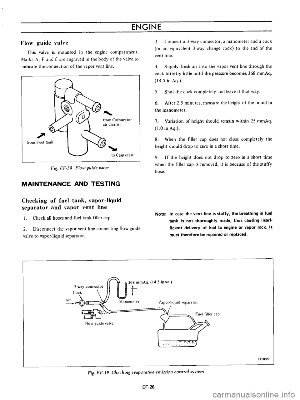
This
valve
is
mounted
in
the
engine
compartment
f
tHks
A
F
and
C
are
engraved
in
the
body
of
the
valve
to
indicate
the
connection
of
the
vapor
vent
line
l
l
1
from
Fuel
tank
to
Crankcase
Fig
EF
3B
Flow
guide
valve
MAINTENANCE
AND
TESTING
Checking
of
fuel
tank
vapor
liquid
separator
and
vapor
vent
line
Check
all
hoses
and
fuel
tank
filler
cap
2
Disconnect
the
vapor
vent
line
connecting
flow
guide
valve
to
vapor
liquid
separator
Flow
guide
valve
3
Connect
a
J
way
connector
a
manometer
and
a
l
ul
k
or
an
equivalent
3
wav
change
cock
to
the
end
of
the
vent
line
4
Supply
fresh
air
into
the
vapor
vent
line
through
the
cock
little
by
little
until
the
pressure
becomes
368
romAq
14
5
in
Aq
5
Shut
the
cock
completely
and
leave
it
that
way
6
After
2
5
minutes
measure
the
height
uf
the
liquid
in
the
manometer
7
Variation
of
height
should
remain
within
25
mmAq
1
0
in
Aq
8
When
the
filler
cap
does
not
close
completely
the
height
should
drop
to
zero
in
a
short
time
9
I
f
the
height
docs
not
drop
to
zero
in
a
short
time
when
the
filler
cap
is
removed
it
is
because
of
the
stuffy
hose
Note
In
case
the
vent
line
is
stuffy
the
breathing
in
fuel
tank
is
not
thoroughly
made
thus
causing
insuf
ficient
delivery
of
fuel
to
engine
or
vapor
lock
It
must
therefore
be
repaired
or
replaced
1
m
eparator
1
Fuel
filler
cap
Y
XI
EC029
Fig
EF
39
Checking
evaporative
emission
control
system
EF
26
Page 418 of 513

FUEL
SYSTEM
Checking
fuel
tank
vacuum
relief
valve
operation
Remove
fuel
filler
cap
and
see
if
it
functions
properly
as
follows
Wipe
clean
valve
housing
and
have
it
in
your
mouth
2
Inhale
air
A
slight
resistance
accompanied
by
valve
indicates
that
valve
is
in
good
mechanical
condition
Note
also
that
by
further
inhaling
air
the
resistance
should
be
disappeared
with
valve
clicks
3
If
valve
seems
to
be
clogged
or
if
no
resistance
is
felt
replace
cap
as
an
assembled
unit
1
1
1I
L
CD
hl
cv
CID
t
I
Valve
2
Valve
housing
I
I
Spring
Valve
seat
Fig
EF
40
Fuel
filleT
cap
EF
27
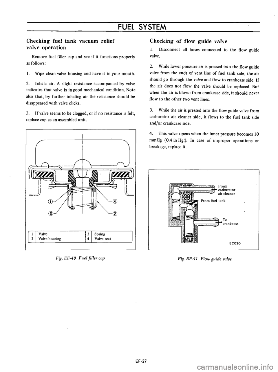
Checking
of
flow
guide
valve
1
Disconnect
all
hoses
connected
to
the
flow
guide
valve
2
While
lower
pressure
air
is
pressed
into
the
flow
guide
valve
from
the
ends
of
vent
line
of
fuel
tank
side
the
air
should
go
through
the
valve
and
flow
to
crankcase
side
If
the
air
does
not
flow
the
valve
should
be
replaced
But
when
the
air
is
blown
from
crankcase
side
it
should
never
flow
to
the
other
two
vent
lines
3
While
the
air
is
pressed
into
the
flow
guide
valve
from
carburetor
air
cleaner
side
it
flows
to
the
fuel
tank
side
and
or
crankcase
side
4
This
valve
opens
when
the
inner
pressure
becomes
10
romHg
0
4
in
Hg
In
case
of
improper
operations
or
breakage
replace
it
iFrom
r
carburetor
air
cleaner
From
fuel
tank
To
r
crankcase
j
iJ
i
ill
1
1
EC030
Fig
EF
4
J
Flow
guide
valve