Page 182 of 252

FRONT
AXLE
FRONT
SUSPENSION
AND
STEERING
177
5
Check
front
hub
for
cracks
and
damage
Re
place
1f
defectIve
6
Check
thrust
bearmg
for
wear
damage
rust
and
ease
of
rotatIon
Replace
1f
defectIve
Front
Suspension
Installation
1
Remstallation
is
the
reverse
of
removal
2
Apply
hght
coatIng
of
multI
purpose
grease
to
all
shdmg
parts
3
Install
bushmg
carefully
so
that
grease
groove
IS
on
the
upper
Side
and
the
bushmg
Joint
is
faced
rearward
Remove
grease
mpple
and
dn11
grease
hole
through
bushmg
through
hole
With
an
0
1181
m
3mm
dn11
Remove
metal
shaVlDgs
and
burrs
Ream
the
mner
d1ameter
of
the
bushing
to
07878
to
0
7888
m
20
010
to
20035mm
4
Install
thrust
bearmg
so
that
the
covered
face
Side
is
upward
5
Push
up
the
bottom
of
the
spmdle
hghtly
Measure
clearance
and
select
a
spmdle
shim
to
prOVide
the
followmg
clearance
standard
Clearance
0
001
In
004mm
ShIms
are
available
m
vanous
thicknesses
6
FIt
kmg
pm
and
make
certam
It
operates
smoothly
7
Apply
sealer
to
new
plug
and
install
8
Install
bearmg
outer
race
Fill
wheel
hub
and
hub
cap
With
multI
purpose
grease
Fill
space
between
wheel
bearing
rollers
and
grease
seal
hp
pocket
With
multI
purpose
grease
Make
cer
tam
wheel
beanngs
are
coated
completely
9
Apply
multI
purpose
grease
to
spmdle
shaft
wheel
bearmg
washer
and
to
the
wheel
bearmg
lock
nut
10
Make
certam
that
no
dIrt
or
foreign
matenal
IS
permitted
m
contact
with
parts
or
grease
dunng
assembly
Wheel
Bearing
Adjustment
1
Install
spindle
nut
and
torque
to
23
1
to
24
6
ft
lb
3
2
to
3
4
kg
m
2
Turn
wheel
hub
a
few
tImes
m
both
the
clock
Wise
and
counterclockwISe
directIon
Recheck
the
spmdle
nut
tighmess
3
Back
off
spmdle
nut
from
40
to
70
degrees
until
hole
m
spmdle
and
nut
COinCIde
Insert
cotter
pm
and
bend
over
around
nut
4
Turn
wheel
hub
a
few
turns
in
both
d1rectIons
to
seat
bearmg
Check
the
startmg
torque
of
the
hub
With
a
spring
gauge
as
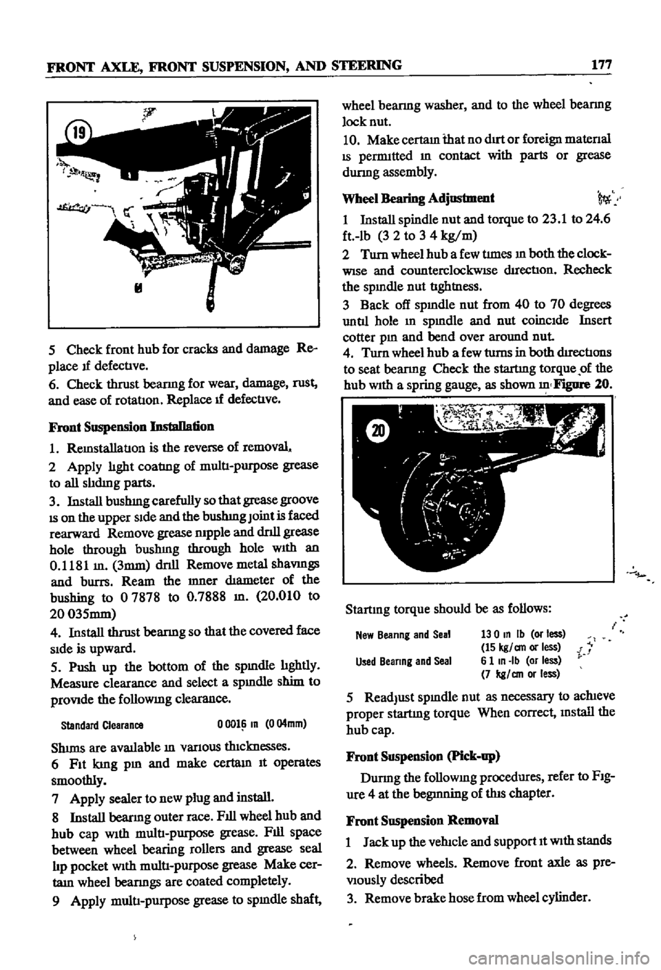
shown
Figure
20
Startmg
torque
should
be
as
follows
New
Beanng
and
Seal
130
In
Ib
or
less
15
kgl
an
or
less
i
Used
Beanng
and
Seal
6
1
In
Ib
or
less
7
kgl
an
or
less
5
ReadJust
spmdle
nut
as
necessary
to
achieve
proper
startmg
torque
When
correct
mstall
the
hub
cap
Front
Suspension
Pick
up
Durmg
the
followmg
procedures
refer
to
FIg
ure
4
at
the
begmning
of
this
chapter
Front
Suspension
Removal
1
Jack
up
the
vehicle
and
support
It
With
stands
2
Remove
wheels
Remove
front
axle
as
pre
Viously
described
3
Remove
brake
hose
from
wheel
cylinder
Page 191 of 252
186
CHAPTER
TIURTEEN
STEERING
SERVICE
DATA
AND
SPECIFICATIONS
r
SpeaficatJons
Sedan
Wagon
P1c11
up
Type
Reclrculatmg
Ball
Reclrculatmg
Ball
Gear
Ratio
1501
1981
Steenng
Wheel
Diameter
159m
405mm
157m
400mm
Wonn
Beanng
Shim
Thickness
0059
m
1
5mm
0059
m
1
5mm
011
CapacJ
y
o
7
pts
0
33
hter
o
7
pts
0
33
hter
Imtlal
Steering
Wheel
Turnmg
Torque
3552mlb
3
5
5
2
In
Ib
4
6
kg
an
4
6
kg
an
End
Clearance
of
Sector
Shaft
AdJustmg
Screw
o
0004
0
0012
m
00004
00012
m
0
01
0
03mm
0
01
0
03mm
Tiglrtenlng
Torque
Flange
Bolts
13
18
ft
Ib
13
18
ft
Ib
1
8
2
5
kg
m
1
8
2
5
kg
m
Gear
Ann
100
ft
Ib
14
kg
m
100
ft
lb
14
kg
m
Gear
Housmg
72
ft
Ib
10
kg
m
27
ft
Ib
3
7
kg
m
dJustmg
Screw
Nut
13
18
ft
Ib
13
18
ft
Ib
y
1
8
2
5
kg
m
1
8
2
5
kg
m
dler
Ann
Bolts
32
44
ft
rb
43
50
ft
Ib
4
6
kg
m
6
7
kg
m
Idler
Arm
Nut
39
55
ft
Ib
43
50
ft
lb
5
8
kg
m
6
7
kg
m
St
I
j
i
I
i
1
l
I
I
Page 209 of 252
204
CHAPTER
FOURTEEN
Table
1
BRAKE
SERVICE
DATA
AND
SPECIFICATIONS
continued
Sedan
Wagon
Pick
up
Tightening
Torque
ft
lb
Ikg
m
Fulcrum
pm
25
3
to
28
9
253to289
3
5
to
4
0
3
5
to
4
0
Master
cylinder
mounting
bolts
15
2
to
18
1
152
to
18
1
2
Ito
2
5
2
1
to
2
5
Front
brake
wheel
cylinder
108
to
152
30
4
to
37
6
1
5
to
2
1
4
2
to
5
2
Rear
brake
wheel
cylinder
10
8
to
15
2
10
8
to
13
0
1
5
to
2
1
1
5
to
1
8
Rotor
fixing
bolts
28
2
to
38
3
39to53
Brake
hose
to
wheel
cylinder
123
to
14
5
123
to
14
5
1
7
to
2
0
1
7
to
2
0
Page 245 of 252

l
INDEX
239
Rear
suspensIOn
wagon
Removal
40
92
Servlcmg
161
Termmals
94
Tightening
torques
162
Test
diagnosIs
97
Testmg
96
Troubleshootmg
10
5
Steenng
also
see
Suspension
front
I
Exploded
views
182
185
L
Seats
SpecIfications
186
DescnptIon
228
Troubleshooting
16
Exploded
View
front
4
door
sedan
232
SuspensIOn
front
pick
up
Exploded
VIew
front
pick
up
228
Axle
removal
175
Service
hmts
4
Inspection
and
repair
179
Shock
absorbers
sedan
154
Installation
179
Shock
absorbers
wagon
162
Posture
adjustment
181
Spark
plugs
Removal
177
CondlllOn
chart
21
Wheel
abgnment
182
InspectIon
and
servlcmg
21
Wheel
bearmg
adjustment
177
Recommended
types
112
Suspension
front
sedan
and
wagon
SpecificatIOns
and
tables
Inspection
and
repair
176
Adjustment
and
wheel
alignment
175
InstallatIOn
177
Brake
service
data
203
204
Lower
ball
Jomt
174
Brakes
203
204
Spnng
and
strut
assembly
173
Camshaft
beanngs
48
Stabilizer
173
Caster
and
camber
sedan
and
wagon
175
TenSIOn
rod
173
Clutch
134
Transverse
bnk
174
Clutch
service
data
134
Wheel
beanngs
177
Connectmg
rod
beanng
underslzes
52
Wheel
hubs
and
bearmgs
168
173
Dlstnbutor
112
SWItches
Dnveshaft
147
DescnptIon
205
Dnveshaft
service
dala
147
Exploded
View
through
1969
208
Engme
60
61
Exploded
view
1970
1972
207
Engme
service
data
60
61
General
4
Mam
bearmg
underslzes
52
T
Piston
rmg
gap
50
Rear
suspenSIOn
pick
up
167
Tail
gate
228
233
Rear
suspensIOn
torques
wagon
162
TenSIOn
rod
sedan
and
wagon
173
Steermg
186
Thermostat
TransmiSSion
manual
144
DescnptIon
89
TransmiSSion
service
data
manual
144
Inspection
and
replacement
89
Valve
spnng
47
Removal
89
Sprmg
and
strut
assembly
sedan
and
wagon
173
Tires
Spnngs
sedan
154
Wear
analYSIS
17
Stabilizer
sedan
and
wagon
173
TransmiSSion
automatic
Starter
Downshift
solenOid
147
Armature
95
Inhlbllor
SWItch
148
Beanngs
96
Kick
down
SWitch
147
Brush
holder
96
Lmkage
mspectIon
and
adjustment
148
Brushes
and
lead
WIre
95
011
checks
147
Cleaning
mspectIon
and
repair
94
Oil
leakage
147
Construcllon
92
TransmiSSion
manual
Disassembly
92
DescnptIon
134
Exploded
View
93
Disassembly
138
Field
COIl
94
Exploded
view
138
Magnetic
SWItch
96
Gear
assembly
exploded
view
139
Magnetic
SWItch
assembly
test
97
Inspection
and
repair
141
Operation
91
Installation
143
Overrunnmg
clutch
96
Reassembly
and
adjustment
142
Reassembly
96
Removal
134
Page:
< prev 1-8 9-16 17-24