1968 DATSUN 510 wheel torque
[x] Cancel search: wheel torquePage 156 of 252

DIFFERENTIAL
REAR
AXLE
AND
REAR
SUSPENSION
151
4
Lower
the
Jack
and
r
move
dIfferentIal
from
rear
of
vehIcle
See
Figure
4
After
removal
sup
port
suspensIon
member
wIth
a
stand
to
prevent
distortlon
and
damage
to
the
Insulators
Differential
Inspection
Sedan
The
followmg
mspectIon
can
be
done
WIthout
disassembly
of
the
dIfferential
If
abnormalitIes
or
damage
eXiSts
refer
further
servIce
and
reparr
to
your
dealer
1
Check
the
tooth
contact
pattern
With
lead
oXide
at
two
or
three
pomts
after
removmg
rear
cover
Refer
to
Figure
5
which
shows
the
cor
rect
contact
pattern
If
the
contact
pattern
IS
m
correct
dIsassembly
and
adjustment
of
dIffer
entlalls
reqUIred
CD
TOE
HEEL
DRIVE
SIDE
HEEL
COAST
SIDE
2
Use
a
dIal
mdtcator
to
measure
backlash
be
tween
the
dnve
gear
and
pmIOn
Backlash
should
be
0
0039
to
0
0079
m
0
10
to
o
20mm
Check
all
gear
teeth
for
damage
and
cracks
3
Check
runout
at
the
rear
of
the
dnve
gear
If
the
tooth
contact
pattern
or
backlash
IS
ab
normal
Runout
should
be
less
than
00031
m
0
08mm
See
Figure
6
4
Rotate
the
gears
and
lIsten
for
SignS
of
de
fective
bearmgs
If
noises
are
eVIdent
the
dIf
ferential
must
be
dIsassembled
and
repaired
CD
Diflerentiallnstallation
Sedan
1
Mount
the
dIfferentIal
assembly
to
the
rear
suspensIOn
member
2
FIt
the
dIfferentIal
mountlng
member
to
the
fittmg
hole
by
pushIng
It
forward
with
a
bar
Torque
the
nuts
to
61
ft
lb
8
5
kg
m
3
Install
axle
dnve
shafts
dnve
shaft
and
handbrake
rear
cable
REAR
AXLE
AND
SUSPENSION
SEDAN
Figure
7
and
Figure
8
page
153
are
ex
ploded
dIagrams
of
the
sedan
rear
axle
and
suspensIOn
The
fully
independent
rear
suspen
SIon
IS
a
semI
traIlIng
arm
deSIgn
With
a
sus
penSIOn
member
suspensIOn
arms
coIl
spnngs
and
hydraulIc
shock
absorbers
The
wheel
bearings
are
lIfetime
lubncated
Rear
Axle
and
Suspension
Removal
Sedan
1
Jack
up
the
rear
of
the
veh1cle
and
support
It
on
stands
2
Remove
wheels
3
Refer
to
Figure
9
and
dtsconnect
handbrake
lInkage
and
rerum
sprmg
Remove
tall
pIpe
and
muffler
4
DISconnect
brake
hose
from
brake
tube
Re
move
four
bolts
holdmg
dnve
shaft
to
dIf
ferential
Lower
dnve
shaft
gently
to
ground
Page 161 of 252
156
CHAPTER
TWELVE
r
IV
rli
@
18
1
P
l
hr
r
J
oJ
1
it
o
1f
f
7
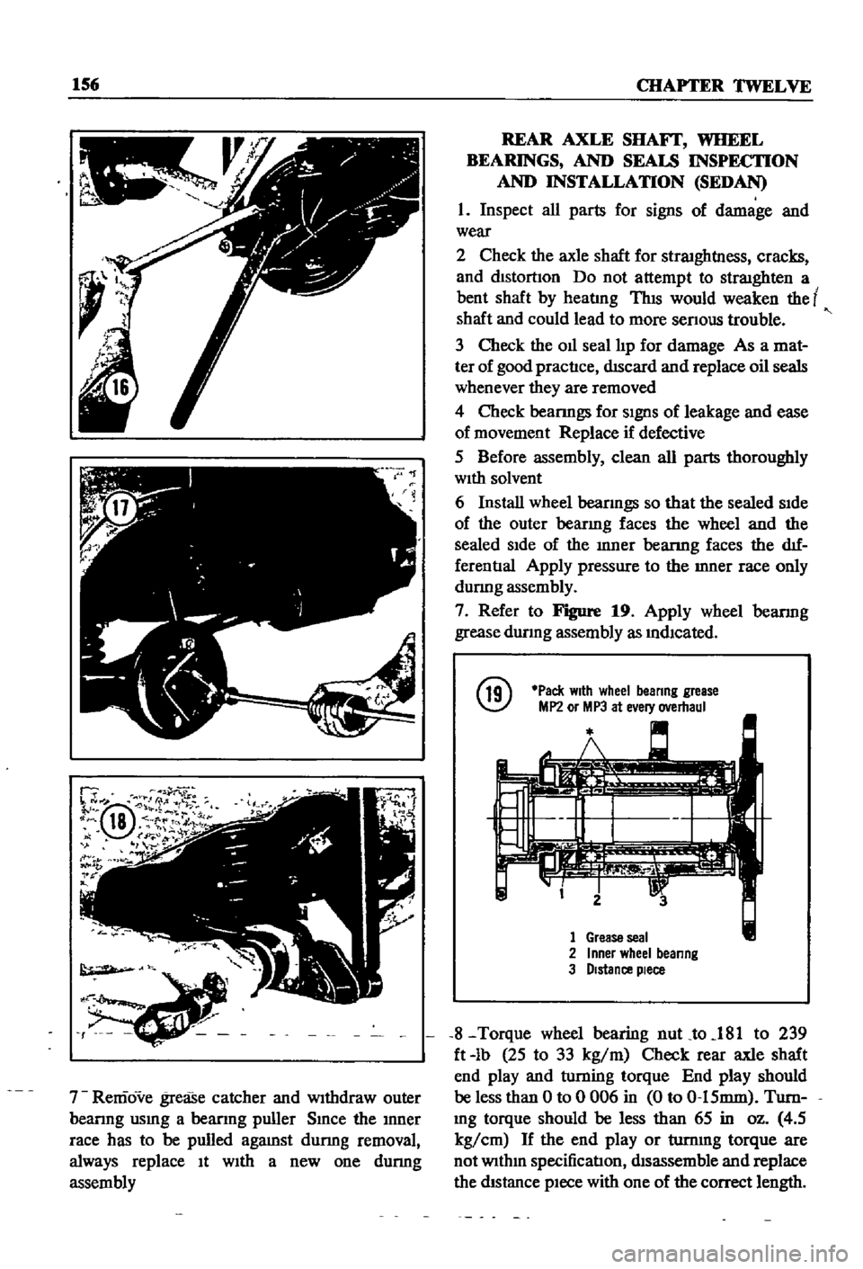
Remove
grease
catcher
and
Withdraw
outer
beanng
usmg
a
beanng
puller
Smce
the
Inner
race
has
to
be
pulled
agamst
dunng
removal
always
replace
It
WIth
a
new
one
dunng
assembly
REAR
AXLE
SHAFf
WHEEL
BEARINGS
AND
SEALS
INSPECTION
AND
INSTALLATION
SEDAN
1
Inspect
all
parts
for
signs
of
damage
and
wear
2
Check
the
axle
shaft
for
straIghtl1ess
cracks
and
dIStortIon
Do
not
attempt
to
straIghten
a
bent
shaft
by
heatlng
ThIS
would
weaken
the
t
shaft
and
could
lead
to
more
senous
trouble
3
Check
the
011
seal
IIp
for
damage
As
a
mat
ter
of
good
practIce
dIScard
and
replace
oil
seals
whenever
they
are
removed
4
Check
bearmgs
for
SIgnS
of
leakage
and
ease
of
movement
Replace
if
defective
5
Before
assembly
clean
all
parts
thoroughly
WIth
solvent
6
Install
wheel
beanngs
so
that
the
sealed
SIde
of
the
outer
bearmg
faces
the
wheel
and
the
sealed
SIde
of
the
Inner
bearmg
faces
the
dIf
ferentIal
Apply
pressure
to
the
Inner
race
only
dunng
assembly
7
Refer
to
Figure
19
Apply
wheel
bearmg
grease
durmg
assembly
as
mdlcated
@
Pack
With
wheel
beanng
grease
MP2
or
MP3
at
e
ery
overhaul
1
Grease
seal
2
Inner
wheel
beanng
3
Distance
piece
8
Torque
wheel
bearing
nuLto
181
to
239
ft
lb
25
to
33
kg
m
Check
rear
axle
shaft
end
play
and
wming
torque
End
play
should
be
less
than
0
to
0
006
in
0
to
0
15mm
Turn
Ing
torque
should
be
less
than
65
in
oz
4
5
kg
cm
H
the
end
play
or
turnmg
torque
are
not
WIthm
specification
dIsassemble
md
replace
the
dIStance
pIece
with
one
of
the
correct
length
Page 165 of 252

160
CHAPTER
TWELVE
@
@
@
I
F
7
Remove
ten
nuts
holdmg
the
drlIerentIal
assembly
to
the
axle
case
and
withdraw
the
differential
aSsembly
Rear
Axle
Inspection
Assembly
nnd
Installation
Wagon
1
Check
the
axle
shafts
for
straighmess
cracks
damage
wear
and
chstortion
Replace
1f
de
fectIve
Do
not
attempt
to
heat
axle
to
straJghten
I
it
as
thiS
wlll
weaken
the
axle
and
could
lead
to
more
senous
trouble
2
Clean
all
parts
thoroughly
With
solvent
3
Check
011
seal
hp
for
damage
Replace
as
requrred
4
Check
the
beanngs
for
damage
and
replace
1f
defective
5
Assemble
the
rear
axle
urnt
in
the
reverse
of
disassembly
6
Use
a
new
gasket
between
axle
cases
and
drlIerentIal
7
The
gear
carner
fixmg
nuts
must
be
torqued
m
a
diagonal
pattern
to
prevent
011
leaks
Tighten
to
145
to
159ft
lb
20
to
22
kg
m
8
Install
the
grease
catcher
beanng
spacer
bearmg
and
new
bearing
collar
on
the
axle
shaft
The
beanng
collar
must
be
fitted
using
an
arbor
press
and
4
to
5
tons
of
force
Make
cectam
to
pack
the
wheel
beanng
With
grease
and
msert
the
wheel
beanng
With
the
seal
Side
toward
the
wheel
9
If
the
011
seal
has
been
replaced
take
care
not
to
damage
it
when
mstallmg
the
axle
shaft
assembly
As
a
matter
of
good
practice
replace
the
011
seal
whenever
the
axle
is
disassembled
10
Refer
to
Figure
27
and
grease
the
mdicated
areas
Torque
all
bolts
as
speCified
11
Adjust
the
aXial
end
play
between
the
wheel
beanng
and
the
recess
in
the
axle
tube
with
adjusting
shims
The
end
play
should
be
00118
to
00197
m
03
to
O
5mm
Check
end
play
with
a
dial
gauge
as
shown
in
Figure
28
Page 167 of 252

162
CHAPTER
TWELVE
14
Coat
the
front
bracket
pm
and
bushmg
and
shackle
pm
and
bushing
With
a
soap
solution
pnor
to
assembly
15
The
front
pm
secunng
nut
and
shock
ab
sorber
lower
end
securmg
nut
should
be
re
tightened
after
the
vehicle
is
sittmg
on
the
ground
16
Make
certaJn
the
shackle
bushmg
flange
is
clamped
evenly
on
both
Sides
SHOCK
ABSORBER
REMOVAL
INSPECTION
AND
INSTALLATION
WAGON
1
Jack
up
the
center
of
the
rear
axle
and
sup
port
th
e
axle
housmg
With
stands
2
Reinove
the
lower
end
of
the
rear
shock
absorber
from
spring
seat
3
Loosen
the
four
bolts
secunng
the
upper
bracket
to
body
Remove
shock
absorber
and
upper
bracket
4
Check
shock
absorber
for
leaks
and
cracks
Check
the
shaft
for
straighmess
Replace
1f
defective
5
Inspect
rubber
bushmgs
for
damage
cracks
and
general
condition
Replace
1f
defective
6
Install
the
shock
absorber
by
reversing
the
procedure
used
durmg
removal
DIFFERENTIAL
pICK
UP
The
dlfferenl1al
carner
IS
made
up
of
alum
mum
alloy
and
uses
a
hyp01d
bevel
gear
Proper
lubncatIon
IS
essenl1al
Check
and
replemsh
the
lubncant
every
3
000
mlles
Drain
and
refill
every
30
000
inlles
Figure
30
IS
a
cross
sectional
View
of
the
pick
up
dIfferential
Difterential
Removal
Pick
up
1
Jack
up
the
rear
wheels
and
support
vehicle
With
stands
2
DIsconnect
dnve
pmlOn
companlOn
flange
to
yoke
connectIon
3
Remove
rear
axles
as
descnbed
later
m
thIS
chapter
4
Remove
dlfferenl1al
gear
assembly
Difterential
Inspection
Pick
up
The
followmg
mspection
can
be
done
Without
disassembly
of
the
d1fferenl1al
If
abnormahties
or
damage
eXiSts
refer
further
serVice
and
reparr
to
your
dealer
1
Check
the
tooth
contact
pattern
WIth
lead
OXide
at
two
or
three
pomts
after
remoVlDg
rear
cover
Refer
to
FIgure
5
for
correct
contact
pattern
If
the
pattern
IS
faulty
disassembly
and
adJustment
of
the
dIfIerentialIs
required
2
Measure
backlash
between
dnve
gear
and
pmlOn
With
a
dial
mdlcator
Backlash
should
be
00051
to
0
0071
m
013
to
0
18mm
3
Rotate
the
gears
and
lISten
for
SignS
of
bear
mg
noise
4
Inspect
gear
teeth
for
SIgnS
of
damage
or
cracks
Difterential
Installation
Pick
up
Install
the
differential
by
reversmg
the
pro
cedures
used
dunng
removal
REAR
AXLE
AND
SUSPENSION
pICK
UP
The
rear
axle
IS
of
the
semi
floatIng
type
The
rear
wheels
use
tapered
roller
beanngs
Figure
31
IS
a
cross
sectional
view
of
the
rear
axle
REAR
SUSPENSION
TORQUE
TIGHTENING
SPECIFICATIONS
WAGON
Shock
absorber
upper
bracket
to
body
bolts
Shock
absorber
to
upper
bracket
lock
nuts
Shock
absorber
to
lower
bracket
lock
nuts
Rear
spnng
U
bolt
nuts
Shackle
nuts
Front
pm
nuts
Front
bracket
flxmg
nuts
Brake
dISC
to
rear
housmg
bolts
DifferentIal
carner
to
axle
housmg
bolt
Dnve
shaft
flange
nuts
11
to
18
ft
Ib
1
5
to
2
5
kg
m
12
to
16
ft
db
17
to
2
2
kg
m
25
to
33
ft
Ib
35
to
45
kg
m
43
to
47
ft
Ib
60
to
6
5
kg
m
32
to
36
ft
Ib
45
to
50
kg
m
32
to
36
ft
Ib
45
to
5
0
kg
m
13
to
17
ft
Ib
18
to
23
kg
m
20
to
28
ft
Ib
28
to
3
9
kg
m
14
to
16
ft
Ib
20
to
2
2
kg
m
20
to
28
ft
Ib
28
to
3
9
kg
m
Page 170 of 252
DIFFERENTIAL
REAR
AXLE
AND
REAR
SUSPENSION
165
2
Check
wheel
bearmgs
for
damage
or
noise
Replace
them
If
defective
3
Be
sure
to
use
new
011
seals
and
lockwashers
4
FIt
beanng
cup
and
grease
seal
to
cage
Tap
WIth
a
brass
hammer
while
fittIng
FIll
grease
seal
IIp
With
wheel
beanng
grease
after
fittmg
5
Install
brake
diSC
and
beanng
cage
on
axle
Fit
bearmg
cone
With
brass
bar
6
Tighten
lock
nut
Place
faced
Side
of
nut
to
washer
SIde
so
that
washer
IS
not
damaged
Torque
lock
nut
to
10S
to
145
ft
lb
15
to
20
kg
m
7
Match
washer
IIp
With
groove
m
nut
tIghten
nut
and
bend
washer
carefully
to
prevent
hp
damage
S
Use
a
brass
bar
to
fit
011
seal
to
tube
end
When
fitted
apply
grease
to
the
hp
Be
careful
not
to
deform
seal
or
damage
hp
9
Completely
fill
bearmg
With
grease
10
Install
shaft
AdJust
aXial
clearance
With
shIms
See
Figure
37
Clearance
should
be
0
012
to
0
035
m
0
3
to
09mm
Standard
shIm
thickness
IS
0
059
m
1
5mm
@
11
Install
other
shaft
AdJust
aXlal
clearance
With
shIm
Clearance
should
be
0
OOOS
to
0
0059
m
002
to
0
15mm
12
Install
bolts
and
torque
to
26
to
34
ft
lb
3
6
to
4
7
kg
m
REAR
SUSPENSION
PICK
UP
The
rear
suspension
IS
a
banJO
type
ngId
suspensIOn
With
parallel
semI
elhpnc
leaf
spnngs
Front
and
rear
ends
of
the
springs
are
secured
on
the
frame
with
rubber
bushmgs
Shock
absorbers
are
mstalled
on
the
cross
mem
ber
from
the
spnng
lower
pad
Figure
38
next
page
IS
an
exploded
dIagram
of
the
rear
sus
pensIOn
Rear
Suspension
Assembly
Removal
Pick
up
1
Jack
up
rear
of
vehicle
and
support
It
With
stands
Remove
wheels
2
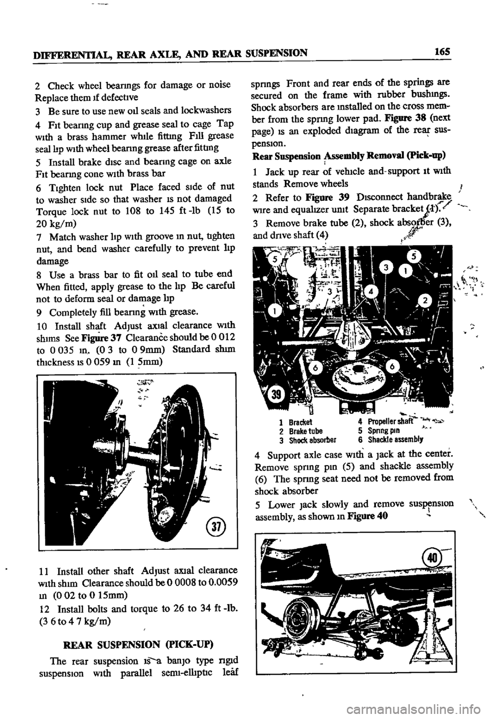
Refer
to
Figure
39
DIsconnect
handbrake
Wire
and
equalIZer
unit
Separate
bracketJt
r
3
Remove
brake
tube
2
shock
absorller
3
and
dnve
shaft
4
r
r
0
it
1
Bracket
4
Propeller
shaft
2
Brake
tube
5
Spnng
pm
3
Shock
absorber
6
Shackle
assembly
4
Support
axle
case
With
a
Jack
at
the
center
Remove
spnng
pm
5
aJId
shackle
assembly
6
The
sprmg
seat
need
not
be
removed
from
shock
absorber
5
Lower
Jack
slowly
and
remove
susp
nslOn
assembly
as
shown
m
Figure
40
Page 177 of 252
17
CHAPTER
THIRTEEN
CD
7
Remove
bearing
collar
and
extract
the
outer
beanng
cage
8
Use
a
screwdriver
to
remove
front
hub
grease
seal
and
imIer
bearmg
cage
9
Use
a
dnft
to
punch
out
the
outer
and
mner
race
of
the
outer
bearmgs
Punch
out
imIer
bearing
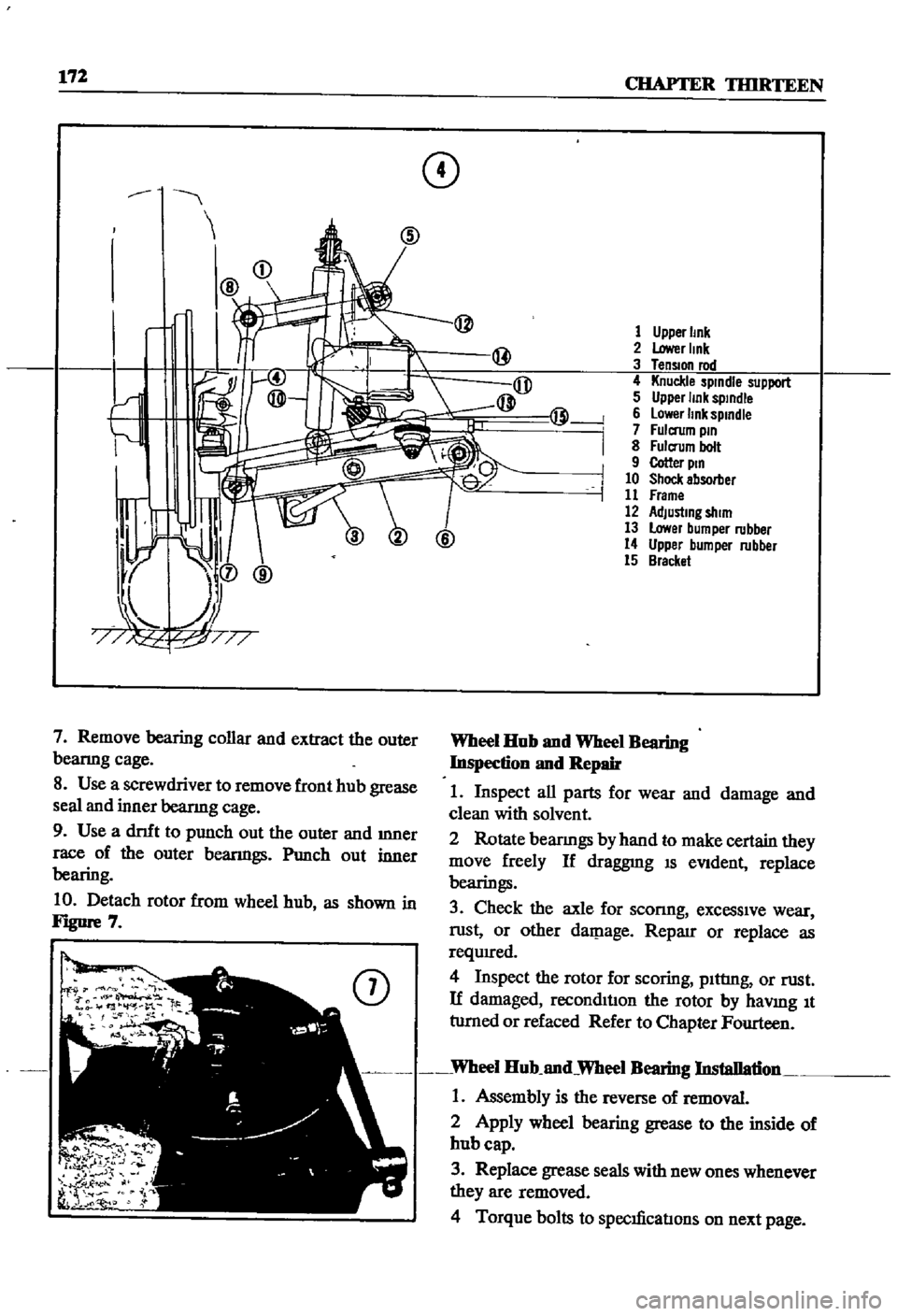
10
Detach
rotor
from
wheel
hub
as
shown
in
FJgUre
7
@
1
Upper
Imk
2
Lower
Imk
3
TenSIOn
rod
4
Knuckle
spindle
support
5
Upper
link
sptndle
6
lower
link
spmdle
7
Fulcrum
pm
8
Fulcrum
bolt
9
Cotter
ptn
10
Shock
absorber
11
Frame
12
AdJustmg
shim
13
Lower
bumper
rubber
14
Upper
bumper
rubber
15
Bracket
Wheel
Hub
nnd
Wheel
Bearing
Inspection
nnd
Repair
1
Inspect
all
parts
for
wear
and
damage
and
clean
with
solvent
2
Rotate
bearmgs
by
hand
to
make
certain
they
move
freely
If
draggnIg
IS
eVident
replace
bearings
3
Check
the
axle
for
sconng
excessive
wear
rust
or
other
daJP
age
Reparr
or
replace
as
requIred
4
Inspect
the
rotor
for
scoring
pIttIng
or
rust
If
damaged
reconditIon
the
rotor
by
haVlDg
It
tumed
or
refaced
Refer
to
Chapter
Fourteen
Wheel
Hub
nnd
Wheel
Bearing
Installation
1
Assembly
is
the
reverse
of
removal
2
Apply
wheel
bearing
grease
to
the
inside
of
hub
cap
3
Replace
grease
seals
with
new
ones
whenever
they
are
removed
4
Torque
bolts
to
specIficatIons
on
next
page
Page 179 of 252
174
CHAPTER
THIRTEEN
Spring
and
StnJt
Assembly
Removal
nnd
Installation
1
Jack
up
the
front
of
the
car
and
support
it
on
stands
2
Remove
front
wheel
3
Detach
brake
hose
connector
at
frame
Re
move
lock
spnng
and
disconnect
brake
hose
from
brake
tube
Plug
up
end
of
tube
so
that
brake
f1wd
will
not
leak
out
4
D
etacb
tensiQn
rod
fi
g
bolts
lld
stabilizer
fixmg
nut
Remove
from
transverse
hnk
5
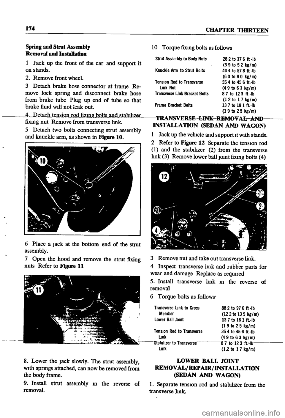
Detach
two
bolts
connectmg
strut
assembly
and
knuckle
arm
as
shown
in
Figure
10
6
Place
a
Jack
at
the
bottom
end
of
the
strut
assembly
7
Open
the
hood
and
remove
the
strut
fixing
nuts
Refer
to
Figure
11
8
Lower
the
Jack
slowly
The
strut
assembly
With
spnngs
attached
can
now
be
removed
from
the
body
frame
9
Install
strut
assembly
m
the
reverse
of
removal
10
Torque
fiXlng
bolts
as
follows
Strut
Assembly
to
Body
Nuts
282
to
37
6
fl
Ib
3
9
to
5
2
kg
m
434
to
578
fl
Ib
60
to
80
kg
m
35
4
to
45
6
flAb
49
to
6
3
kg
m
8
7
to
123
fl
Ib
12
to
17
kg
m
13
7
to
18
1
flAb
19
to
25
kg
m
TRANSVERSE
l
INK
REMOV
AL
AND
INSTALLATION
SEDAN
AND
WAGON
1
Jack
up
the
vehicle
and
supportIt
With
stands
2
Refer
to
Figure
12
Separate
the
tensIOn
rod
1
and
the
stabIlIzer
2
from
the
transverse
hnk
3
Remove
lower
ball
Jomt
fixmg
bolts
4
Knuckle
Ann
to
Strut
Bolts
TenSion
Rod
to
Transverse
L
mk
Nut
Transverse
Unk
Bracket
Bolts
Frame
Bracket
Bolts
3
Remove
nut
and
take
out
transverse
link
4
Inspect
transverse
hnk
and
rubber
parts
for
wear
and
damage
Replace
as
reqwred
5
Install
transverse
hnk
III
the
reverse
of
removal
6
Torque
bolts
as
follows
Transverse
L
mk
to
Cross
Member
L
ower
Ball
Jomt
882
to
976
fl
lb
122
to
13
5
kg
m
13
7
to
18
1
flAb
19
to
25
kg
m
TenSion
Rod
to
Transverse
354
to
45
6
fl
lb
L
lnk
49
to
63
kg
m
Stabilizer
to
Transverse
8
7
to
123
fl
lb
L
lnk
1
2
to
17
kg
m
LOWER
BALL
JOINT
REMOVAL
REPAIR
INSTALLATION
SEDAN
AND
WAGON
1
Separate
tensIOn
rod
and
stabilizer
from
the
transverse
hnk
Page 180 of 252
FRONT
AXLE
FRONT
SUSPENSION
AND
STEERING
175
2
Remove
bolt
cormectIng
strut
and
knuckle
arm
3
Remove
cotter
pm
and
lower
ball
Joint
4
Separate
lower
ball
Jomt
from
knuckle
arm
5
Remove
bolts
for
lower
ball
Jomt
Separate
transverse
lmk
from
lower
ball
Joint
6
Inspect
ball
Jomt
and
dust
cover
for
wear
or
damage
Replace
as
requIred
If
end
play
m
the
aXial
dIrectIon
of
the
ball
Jomt
exceeds
00012
to
0
0136
m
0
03
to
0
6mm
replace
It
7
Install
ball
Jomt
m
the
reverse
of
removal
Grease
It
through
the
grease
mpple
Take
care
to
fill
the
caVity
slowly
so
that
grease
does
not
come
out
from
the
clamp
portIon
8
Torque
bolts
as
follows
Lower
Ball
JOint
to
Transverse
Link
Ball
Stud
Nut
13
7
to
18
1
fl
Ib
19
to
25
kgfm
398
to
55
0
fl
Ib
55
to
76
kgfm
43
4
to
57
8
flAb
60
to
80
kgfm
35
4
to
45
6
flAb
49
to
63
kgfm
87
to
12
3
fl
lb
12
to
17
kgfm
Knuckle
Ann
to
Strut
TenSion
Rod
to
Transverse
Link
Stabilizer
to
Transverse
Link
FRONT
SUSPENSION
ADJUSTMENT
AND
WHEEL
ALIGNMENT
SEDAN
AND
WAGON
Due
to
the
speclahzed
eqUIpment
required
front
suspensIOn
adJustment
and
wheel
ahgn
ment
should
be
referred
to
a
Datsun
dealer
or
front
end
speciahst
The
followmg
specmcations
apply
to
the
sedan
and
wagon
Sedan
Wagon
Caster
1
40
20
00
Camber
1
00
20
10
King
Pin
Incllnallon
8000
7050
Toe
In
0236
to
0
354
In
0118
to
0
236
In
6
to
9mm
3
to
6mm
Steenng
Angle
In
38
to
390
38
to
390
Steenng
Angle
Out
22030
to
330
30
220
30
to
330
30
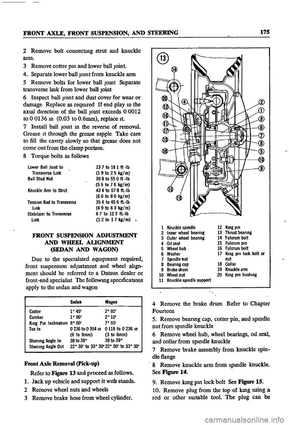
Front
Axle
Removal
Pick
up
Refer
to
Figure
13
and
proceed
as
follows
1
Jack
up
vehIcle
and
support
it
With
stands
2
Remove
wheel
nuts
and
wheels
3
Remove
brake
hose
from
wheel
cylinder
@
@
1
Knuckle
spindle
2
Inner
wheel
beanng
3
Outer
wheel
beanng
4
011
seal
5
Wheel
hub
6
Washer
7
Spindle
nut
8
Beanng
cap
9
Brake
drum
10
Wheel
nut
11
Knuckle
spindle
support
12
KUlg
pin
13
Thrust
beanng
14
fulaum
bolt
15
Fulcrum
pin
16
Fulaum
bolt
17
King
pin
lock
bolt
or
nut
18
Collar
19
Knuckle
ann
20
King
pin
busllIng
4
Remove
the
brake
drum
Refer
to
Chapter
Fourteen
5
Remove
bearmg
cap
cotter
pin
and
spmdle
nut
from
spmdle
knuckle
6
Remove
wheel
hub
wheel
bearings
011
seal
and
collar
from
spmdle
knuckle
7
Remove
brake
assembly
from
knuckle
spin
dle
flange
8
Remove
knuckle
arm
from
spmdle
knuckle
See
Figure
14
9
Remove
kmg
pm
lock
bolt
See
Figure
15
10
Remove
plug
from
the
top
of
kmg
using
a
rod
or
other
SUItable
tool
The
plug
can
be