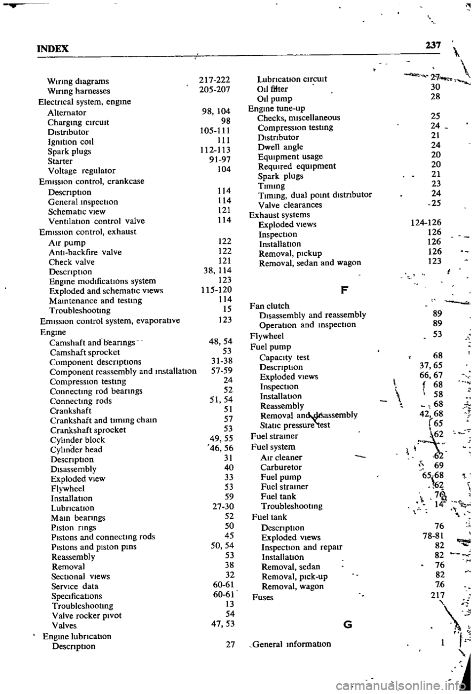
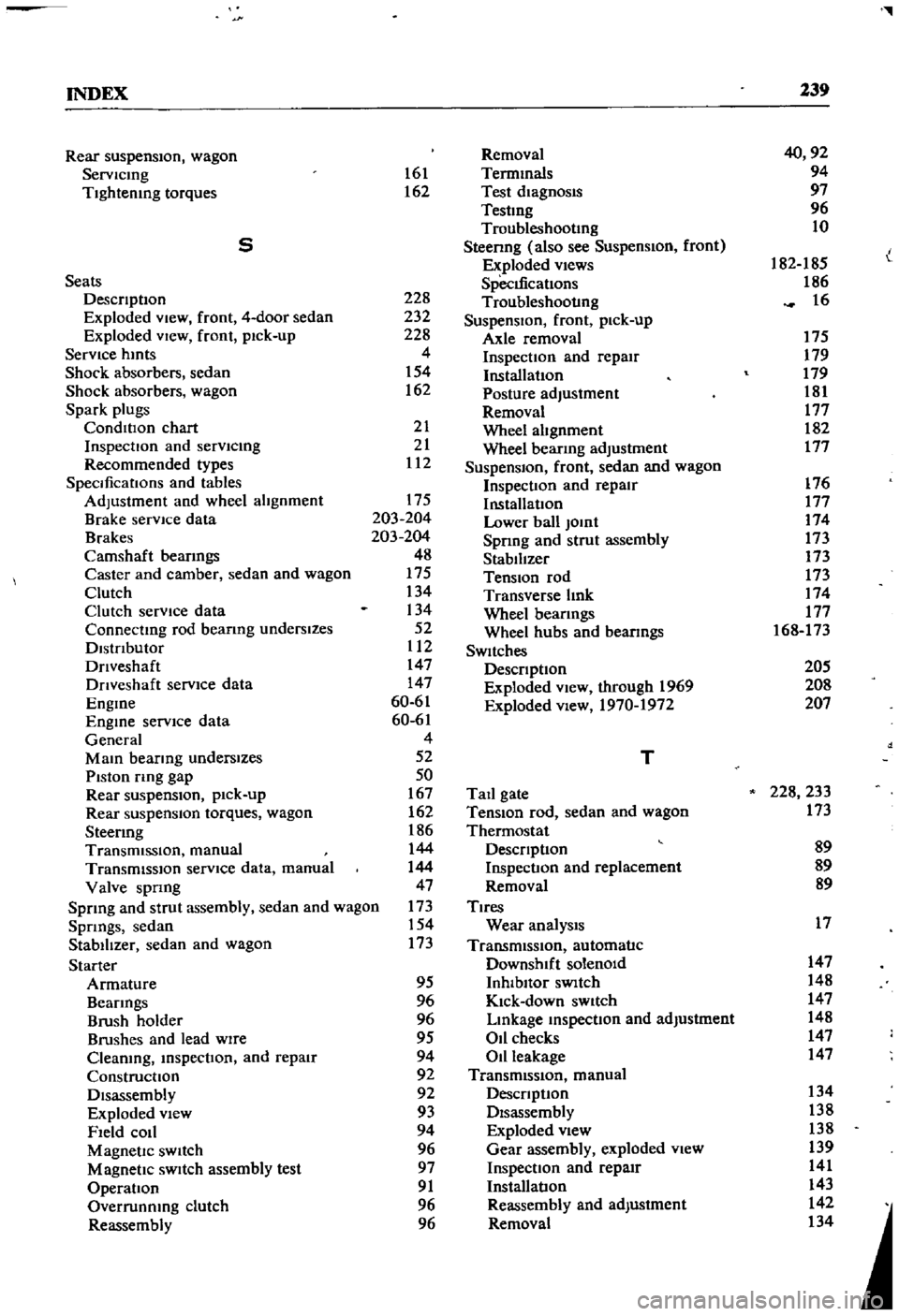
1968 DATSUN 510 spark plugs
[x] Cancel search: spark plugsPage 64 of 252

ENGINE
59
2
Coat
the
pan
gasket
on
both
sides
With
gasket
compound
and
attach
the
oil
pan
to
the
cyhnder
block
Torque
as
specIfied
Manifold
and
Carburetor
Installation
1
Install
the
mtake
and
exhaust
manIfolds
WIth
associated
gasket
to
the
cylmder
head
2
Mount
the
carburetor
and
gasket
to
the
mtake
manIfold
2
Adjust
all
mtake
and
exhaust
valves
to
the
specIfied
clearance
for
a
cold
engme
Clutch
Assembly
Installation
CAUTION
Take
extreme
care
not
to
get
grease
or
011
on
the
clutch
or
flywheel
frlc
hon
contact
surfaces
1
Place
the
clutch
disc
assembly
on
the
flywheel
With
the
longer
chamfered
splmed
end
of
the
dISC
toward
the
transmISSion
2
Visually
align
or
use
a
dummy
splmed
dnve
shaft
to
ahgn
the
diSC
assembly
With
the
flywheel
pilot
beanng
3
Install
and
tighten
the
SIX
bolts
holdmg
the
clutch
cover
assembly
to
the
flywheel
Tighten
the
bolts
a
turn
each
tune
by
diagonal
pattern
until
they
are
tight
Tlghtenmg
torque
should
be
174
to
188ft
lbs
24
to
2
6
kg
m
NOTE
There
are
two
dowels
on
the
flywheel
to
locate
the
clutch
cover
4
Remove
dummy
shaft
If
used
after
the
above
bolts
are
fully
tightened
5
Refit
the
release
bearing
and
translI11Ssion
case
Miscellaneous
Installation
1
Connect
the
fuel
hose
on
the
front
part
of
the
engme
to
the
fuel
pump
and
to
the
carburetor
2
Gap
the
spark
plugs
and
mstall
them
usmg
new
gaskets
3
Coat
the
rocker
arm
cover
gasket
With
sealer
and
position
It
on
the
cylmder
head
4
Install
the
rocker
arm
cover
and
tighten
the
two
thumb
screws
that
hold
it
m
place
5
Install
distrIbutor
makmg
certam
that
the
notch
on
the
distributor
shaft
assembly
mates
With
the
drive
spmdle
Ahgn
the
location
marks
made
dunng
disassembly
so
that
the
distrIbutor
is
positioned
as
before
6
Install
and
tighten
the
bolts
which
hold
the
dIStributor
to
the
front
cover
7
Install
pomts
condenser
and
rotor
8
Replace
distrIbutor
cap
and
attach
spark
plug
Wires
m
the
correct
sequence
Make
certain
that
all
wires
are
firmly
seated
m
the
distrIbutor
cap
and
attached
securely
to
the
spark
plugs
9
HOISt
the
engme
assembly
from
the
work
stand
10
Install
the
alternator
bracket
alternator
and
engme
mounts
to
the
block
11
Install
the
IgnItIon
coil
oil
filter
oil
pressure
SWitch
dipstick
and
water
drain
plug
12
Connect
the
vacuum
Ime
between
the
dis
trIbutor
and
carburetor
13
Connect
the
transIDlSSlOn
to
the
engine
prior
to
mstallatIon
m
the
vehicle
Engine
Installation
Installation
is
the
reverse
of
the
procedures
followed
m
removal
Be
certaIn
thatlall
battery
connections
are
made
that
water
hoses
are
se
cured
wmng
IS
connected
properly
and
that
all
required
bolts
and
mounts
are
mstalled
and
tightened
Replace
the
radiator
fan
belts
and
radiator
shroud
Fill
the
engme
With
the
proper
grade
of
oil
and
the
radiator
With
recommended
coolant
Install
the
hood
to
the
hInges
according
to
the
marks
made
dUrIng
removal
SERVICE
DATA
AND
SPECIFICATIONS
Table
1
covers
servIce
data
and
engme
Speci
fications
Page 117 of 252

112
Table
1
CHAPTER
NINE
DISTRIBUTOR
SPECIFICATIONS
POint
gap
POint
pressure
Shaft
diameter
lower
part
HOUSing
Inner
diameter
Clearance
between
shaft
and
hOUSing
Ammendment
limit
ot
clearance
Shaft
diameter
upper
part
Cam
Inner
diameter
Clearance
between
shaft
and
cam
Weight
piVOt
dIameter
Weight
hole
dIameter
Clearance
between
piVOt
and
hole
Inches
Millimeters
00177
00217
1
10
143
Ibs
o
4902
0004
0008
o
4902
0
0007
o
00004
00015
00031
03150
0002
0006
03150
0
0006
o
00002
00011
o
1969
00004
00010
01969
0
0007
o
o
0004
0
0018
o
45
0
55
o
50
0
65
kg
1245
010
0020
1245
0
018
o
OlD
O
038
008
8
005
014
8
0
015
o
o
005
0
029
5
010
028
5
0
018
0
001
0046
@
@
r
COllIS
not
pOSSIble
and
It
must
be
replaced
1f
found
defectIve
Inspect
the
connectIons
to
the
coll
to
make
certaIn
they
are
clean
and
tIght
Inspect
the
top
of
the
coIl
for
SIgnS
of
cracks
or
damage
and
replace
1f
necessary
The
Ignluon
COllIS
located
on
the
left
SIde
wall
of
the
engme
compartment
and
is
held
In
place
by
two
screws
and
washers
SPARK
PLUGS
The
followmg
spark
plugs
or
then
equivalent
are
recommended
for
the
L16
engme
ChampIon
No
NlOY
AutolIte
No
AG32A
AC
No
44XL
and
NGK
No
BP
6E
Figure
66
shows
spark
plug
constroctIon
They
should
be
re
RING
CENTER
ELECTRODE
TERMINAL
NUT
IS
r
1
n
f
INSULATOR
moved
penodlcally
and
inspected
for
general
condItIon
cleanmg
or
replacement
anl
regap
pmg
Figure
67
IS
a
senes
of
photos
that
show
the
appearance
of
and
pOSSIble
causes
of
spark
plug
problems
If
the
spark
plugs
are
still
usable
they
should
be
cleaned
thorougWy
with
a
sand
blast
Ing
type
cleaner
The
electrodes
should
then
be
filed
flat
and
the
plug
regapped
The
proper
gap
IS
0
031
to
0035
m
0
8
to
0
9mm
Never
use
a
spark
plug
that
has
a
damaged
or
cracked
msulator
Use
extreme
care
when
remOVIng
and
mstallmg
spark
plugs
to
keep
from
crackIng
the
msulator
Always
bend
the
ground
electrode
when
settmg
the
plug
gap
Never
bend
the
center
electrode
Page 243 of 252

INDEX
237
2
7
30
28
WIrIng
diagrams
WIrIng
harnesses
Electncal
system
engme
Alternator
Chargmg
ClfCUlt
Dlstnbutor
IgmtlOn
coIl
Spark
plugs
Starter
Voltage
regulator
Emission
control
crankcase
DescnptIon
General
mspectIon
SchematIc
vIew
VentIlatIOn
control
valve
EmIssIOn
control
exhaust
AIr
pump
AntI
backfire
valve
Check
valve
DescnptlOn
Engme
modificatIons
system
Exploded
and
schematIc
vIews
Mamtenance
and
testIng
Troubleshootmg
Emission
control
system
evaporatIve
Engme
Camshaft
and
beanngs
Camshaft
sprocket
Component
descnptIons
Componenl
reassembly
and
mstallatIon
CompressIOn
testmg
Connectmg
rod
beanngs
Connectmg
rods
Crankshaft
Crankshaft
and
tImmg
cham
Crankshafl
sprocket
Cylmder
block
CylInder
head
DescnptlOn
Disassembly
Exploded
view
Flywheel
InstallatIOn
LubncatIon
MaIO
bearmgs
PIston
nngs
Pistons
and
connectmg
rods
PiStOns
and
piston
pms
Reassembly
Removal
SectIonal
views
ServIce
data
SpeCificatIons
Troubleshootmg
Valve
rocker
PIvot
Valves
Engme
lubncatlon
DescnptIon
217
222
205
207
98
104
98
105
111
111
112
113
9197
104
122
122
121
38
114
123
115
120
114
15
123
48
54
53
31
38
5759
24
52
51
54
51
57
53
49
55
46
56
31
40
33
53
59
27
30
52
50
45
50
54
53
38
32
60
61
60
61
13
54
47
53
114
114
121
114
LubncatlOn
ClfCUlt
011
filter
011
pump
Engme
tune
up
Checks
miscellaneous
Compression
testIng
DIstributor
Dwell
angle
EqUIpment
usage
ReqUIred
eqUIpment
Spark
plugs
Tlmmg
Tlmmg
dual
pomt
dlstnbutor
Valve
clearances
Exhaust
systems
Exploded
views
InspectIon
InstallatIOn
Removal
pickup
Removal
sedan
and
wagon
F
Fan
clutch
DIsassembly
and
reassembly
OperatIon
and
mspectlon
Flywheel
Fuel
pump
Capacity
test
DescnptlOn
Exploded
views
InspectIOn
InstallatIOn
Reassembly
Removal
an
assembly
StatIc
pressure
test
Fuel
stramer
Fuel
system
Air
cleaner
Carburetor
Fuel
pump
Fuel
stramer
Fuel
tank
Troubleshootmg
Fuel
tank
DescnptIon
Exploded
Views
InspectIOn
and
repaIr
Installation
Removal
sedan
Removal
pick
up
Removal
wagon
Fuses
G
27
General
mformatIon
25
24
21
24
20
20
21
23
24
25
124
126
126
126
126
123
l
89
89
53
68
37
65
66
67
68
58
68
42
68
65
1
2v
62
69
65
68
l
6
7
1
l
76
78
81
82
82
76
82
7
6
2
1
F
Page 245 of 252

l
INDEX
239
Rear
suspensIOn
wagon
Removal
40
92
Servlcmg
161
Termmals
94
Tightening
torques
162
Test
diagnosIs
97
Testmg
96
Troubleshootmg
10
5
Steenng
also
see
Suspension
front
I
Exploded
views
182
185
L
Seats
SpecIfications
186
DescnptIon
228
Troubleshooting
16
Exploded
View
front
4
door
sedan
232
SuspensIOn
front
pick
up
Exploded
VIew
front
pick
up
228
Axle
removal
175
Service
hmts
4
Inspection
and
repair
179
Shock
absorbers
sedan
154
Installation
179
Shock
absorbers
wagon
162
Posture
adjustment
181
Spark
plugs
Removal
177
CondlllOn
chart
21
Wheel
abgnment
182
InspectIon
and
servlcmg
21
Wheel
bearmg
adjustment
177
Recommended
types
112
Suspension
front
sedan
and
wagon
SpecificatIOns
and
tables
Inspection
and
repair
176
Adjustment
and
wheel
alignment
175
InstallatIOn
177
Brake
service
data
203
204
Lower
ball
Jomt
174
Brakes
203
204
Spnng
and
strut
assembly
173
Camshaft
beanngs
48
Stabilizer
173
Caster
and
camber
sedan
and
wagon
175
TenSIOn
rod
173
Clutch
134
Transverse
bnk
174
Clutch
service
data
134
Wheel
beanngs
177
Connectmg
rod
beanng
underslzes
52
Wheel
hubs
and
bearmgs
168
173
Dlstnbutor
112
SWItches
Dnveshaft
147
DescnptIon
205
Dnveshaft
service
dala
147
Exploded
View
through
1969
208
Engme
60
61
Exploded
view
1970
1972
207
Engme
service
data
60
61
General
4
Mam
bearmg
underslzes
52
T
Piston
rmg
gap
50
Rear
suspenSIOn
pick
up
167
Tail
gate
228
233
Rear
suspensIOn
torques
wagon
162
TenSIOn
rod
sedan
and
wagon
173
Steermg
186
Thermostat
TransmiSSion
manual
144
DescnptIon
89
TransmiSSion
service
data
manual
144
Inspection
and
replacement
89
Valve
spnng
47
Removal
89
Sprmg
and
strut
assembly
sedan
and
wagon
173
Tires
Spnngs
sedan
154
Wear
analYSIS
17
Stabilizer
sedan
and
wagon
173
TransmiSSion
automatic
Starter
Downshift
solenOid
147
Armature
95
Inhlbllor
SWItch
148
Beanngs
96
Kick
down
SWitch
147
Brush
holder
96
Lmkage
mspectIon
and
adjustment
148
Brushes
and
lead
WIre
95
011
checks
147
Cleaning
mspectIon
and
repair
94
Oil
leakage
147
Construcllon
92
TransmiSSion
manual
Disassembly
92
DescnptIon
134
Exploded
View
93
Disassembly
138
Field
COIl
94
Exploded
view
138
Magnetic
SWItch
96
Gear
assembly
exploded
view
139
Magnetic
SWItch
assembly
test
97
Inspection
and
repair
141
Operation
91
Installation
143
Overrunnmg
clutch
96
Reassembly
and
adjustment
142
Reassembly
96
Removal
134