1900 MITSUBISHI DIAMANTE ignition
[x] Cancel search: ignitionPage 189 of 408
I
5-2, FUELSYSTEM
When there is a problem starting or driving a vehi-
“is there fuel? will often lead to solving most basic
cle, two of the most important checks involve the ig- problems. For ignition system diagnosis and testing,
nition and the fuel systems. The questions most me-
please refer to the information on engine electrical
chanics attempt to answer first, “is there spark?” and
components and ignition systems found earlier in this manual. If the ignition system checks out (there
is spark), then you must determine if the fuel system
is operating properly (is there fuel?).
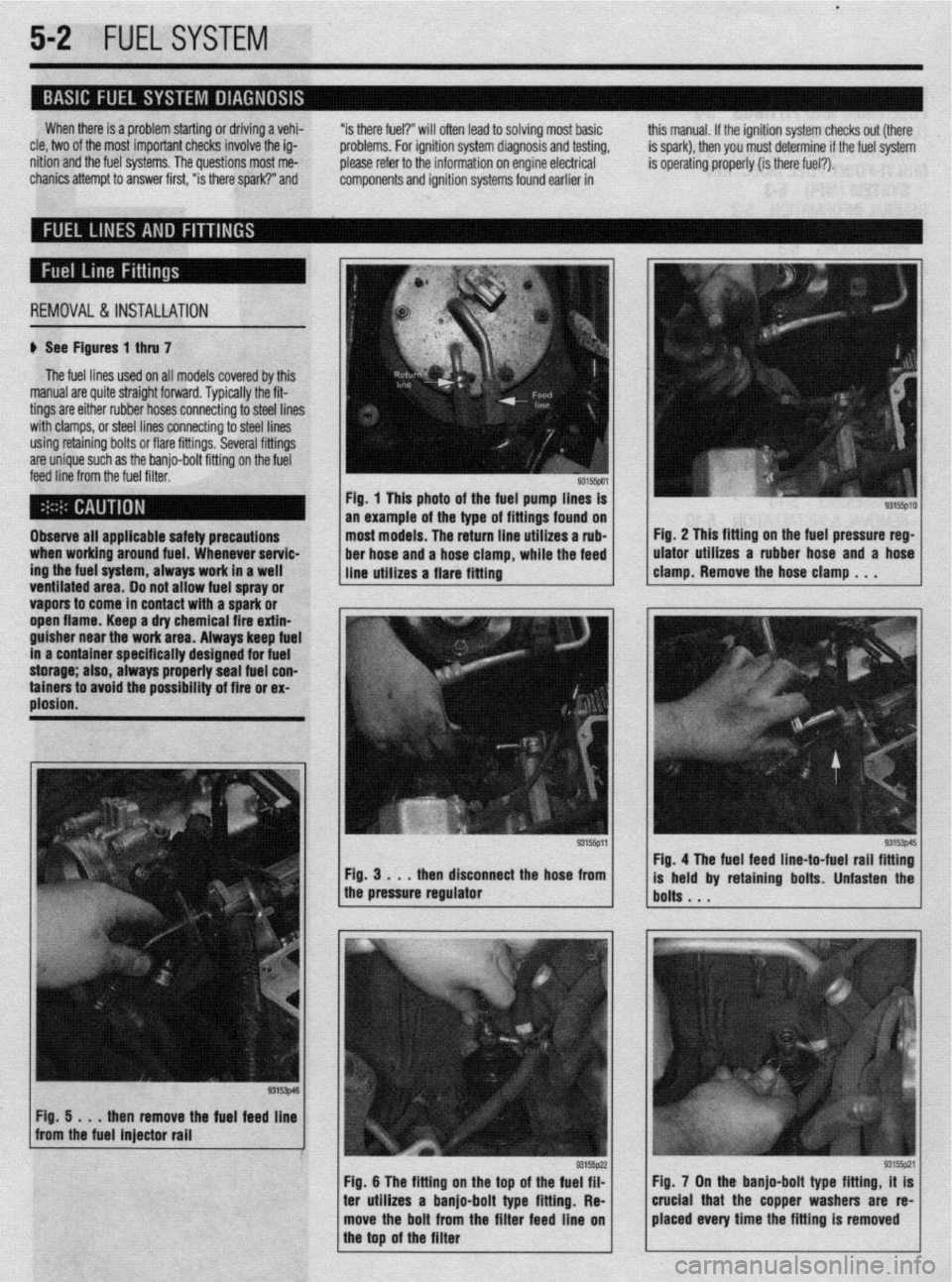
REMOVAL&INSTALLATION
# See Figures 1 thru 7
The fuel lines used on all models covered by this
manual are quite straight forward. Typically the fit-
tings are either rubber hoses connecting to steel lines
with clamps, or steel lines connecting to steel lines
using retaining bolts or flare fittings. Several fittings
are unique such as the banjo-bolt fitting on the fuel
feed line from the fuel filter.
ventitateu area. Do not allow fuel spray or
vapors to come in contact with a spark or
ooen flame. Keen a drv chemical fire extin- Observe all applicable safety precautions
when working around fuel. Whenever servic-
ing the fuel system, always work in a well
___ _ . . . _
guisher near the’work &ea. Always keep fuel
in a container specifically designed for fuel
storage; also, always pmperly seal fuel con-
tainers to avoid the possibility of fire or ex-
plosion. Fig. 1 This photo of the fuel pump lines is
an example of the type of fittings found on
most models. The return line utilizes a rub-
ber hose and a hose clamp, while the feed
line utilizes a flare fitting
ren disconnect the hose from
1 the pressure regulator Fig. 2 This fitting on the fuel pressure reg-
ulator utilizes a rubber hose and a hose
clamp. Remove the hose clamp . . .
93153p45 Fig. 4 The fuel feed line-to-fuel rail fitting
is held by retaining bolts. Unfasten the
bolts . . .
Fig. 5 . . .
then remove the fuel feed line
from the fuel injector rail
I
1 Fig. 6 The fitting on the too of the fueg;?lz
I I
93155pzl Fig. 7 On the banjo-bolt type fitting, it is
ter utilizes a banjo-bolt type fitting. Re-
I I crucial that the copper washers are re-
move the bolt from the filter feed line on placed every time the fitting is removed
the top of the filter
Page 190 of 408
FUELSYSTEM 513
l Always replace worn fuel fitting O-rings with
new. Do not substitute fuel hose or equivalent, where
I
The Multi-Point Injection (MPI) system is electroni-
rally controlled by the Engine Control Module (ECM),
based on data from various sensors. The ECM controls
the fuel flow, idle speed and ignition timing. fuel pipe is installed.
Fuel is supplied to the injectors by an electric in-
tank fuel pump and is distributed to the respective in-
jectors via the main fuel pipe. The fuel pressure ap-
plied to the injector is constant and higher than the
pressure in the intake manifold. The pressure is con-
trolled by the fuel pressure regulator. The excess fuel
is returned to the fuel tank through the fuel return pipe.
When an electric current flows in the injector, the
injector valve is fully opened to supply fuel. Since the
fuel pressure is constant, the amount of the fuel in-
jetted from the injector into the manifold is increased
or decreased in proportion to the time the electric
current flows. Based on ECU signals, the injectors in-
ject fuel to the cylinder manifold ports in firing order. Fuel injection systems remain under pres-
sure after the engine has been turned OFF.
Properly relieve fuel pressure before discon-
neeting any fuel lines. Failure to do so may
result in fire or personal injury.
1. Turn the ignition to the OFF position.
2. Loosen the fuel filler cap to release fuel tank
pressure.
I
The flow rate of the air drawn through the air
cleaner is measured by the air flow sensor. The air
enters the air intake plenum or manifold through the
throttle body. In the intake manifold, the air is mixed
with the fuel from the injectors and is drawn into the
cylinder, The air flow rate is controlled according to
the degree of the throttle valve and the servo motor
openings. The system is monitored through a num-
ber of sensors which feed information on engine con-
ditions and requirements to the ECM. The ECM cal-
culates the injection time and rate according to the
signals from the sensors,
Safety is the most important factor when perform-
ing not only fuel system maintenance but any type of
maintenance. Failure to conduct maintenance and re-
pairs in a safe manner may result in serious personal
injury or death. Maintenance and testing of the vehi-
cle’s fuel system components can be accomplished
safely and effectively by adhering to the following
rules and guidelines.
l To avoid the possibility of fire and personal in-
jury, always disconnect the negative battery cable un-
less the repair or test procedure requires that battery
voltage be applied.
l Always relieve the fuel system pressure prior to
disconnecting any fuel system component (injector,
fuel rail, pressure regulator, etc.), fitting or fuel line
connection. Exercise extreme caution whenever re- Observe all applicable safety precautions
when working around fuel. Whenever servic-
ing the fuel system, always work in a well
ventilated area. Do not allow fuel spray or va-
pors to come in contact with a spark or open
flame. Keep a dry chemical fire extinguisher
near the work area. Always keep fuel in a con-
tainer specifically designed for fuel storage;
also, always properly seal fuel containers to
avoid the possibility of fire or explosion.
3. For the Mirage, Diamante, and 1994-00
Galant, remove the rear seat cushion, then remove
the service cover and detach the fuel pump harness
connector.
4. For the 1990-93 FWD Galant, detach the fuel
pump harness connector located in the area of the
fuel tank. It may be necessary to raise the vehicle to
access the connector.
5. For the 1990-93 AWD Galant, remove the car-
pet from the trunk, locate the fuel tank wiring at the
pump access cover, then detach the wiring.
6. Start the vehicle and allow it to run until it
stalls from lack of fuel. Turn the key to the OFF posi-
tion.
7. Disconnect the negative battery cable, then at-
tach the fuel pump connector. Install the access .
cover, cushion or carpet as necessary.
8. Wrap shop towels around the fitting that is be-
ing disconnected to absorb residual fuel in the lines.
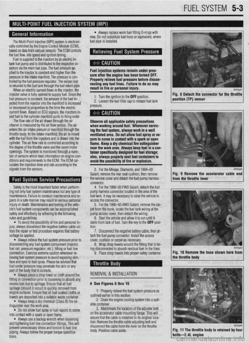
9. Place shop towels into proper safety container. Fig, 8 Detach the connector for the throttle
position (TP) sensor
93153ps5 Fig, 9 Remove the accelerator cable end
from the throttle lever
Fig. IO Remove the hose shown here from
lieving fuel system pressure to avoid exposing skin,
face and eyes to fuel spray. Please be advised that
fuel under pressure may penetrate the skin or any
part of the body that it contacts.
l Always place a shop towel or cloth around the
fitting or connection prior to loosening to absorb any
excess fuel due to spillage. Ensure that all fuel
spillage (should it occur) is quickly removed from
enginesurfaces. Ensure that all fuel soaked cloths or
towels are deposited into a suitable waste container.
l Always keep a dry chemical (Class B) fire ex-
tinguisher near the work area.
l Do not allow fuel spray or fuel vapors to come
into contact with a spark or open flame.
l Always use a backup wrench when loosening’
and tightening fuel line connection fittings. This will
prevent unnecessary stress and torsion to fuel line
piping. Always follow the proper torque specifica-
tions. REMOVAL &INSTALLATION
p See Figures 8 thru 18
1. Properly relieve the fuel system pressure as
outlined earlier in this section.
2. Drain the engine cooling system into a suit-
able container.
3. Matchmark the jocation of the adjuster bolt
on the accelerator cable mounting flange. This will
assure that the cable is installed in its original loca-
tion. Remove the throttle cable adjusting bolt and
disconnect the cable from the lever on the throttle
body. Position cable aside.
Page 194 of 408
FUELSYSTEM 5-7
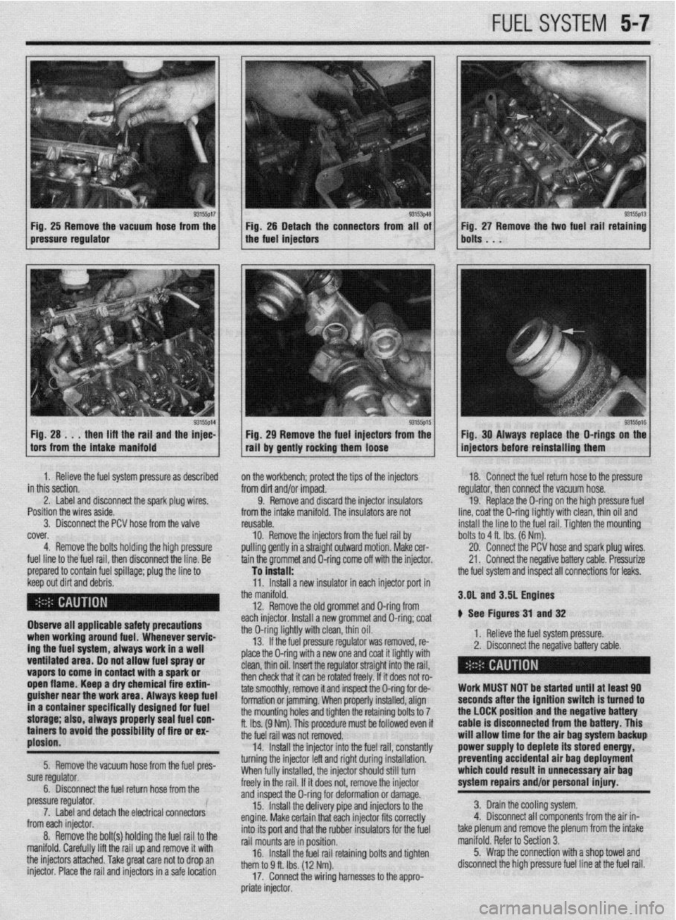
Fig, 25 Remove the vacuum hose from the Fig. 25 Detach the connectors from all of
pressure regulator the fuel injectors
1 H; :A ..;lt;;aft~rgi,i~;yl the ;F: 1 / . 93155p15 1 Fig 29 Remove the fuel injectors from the
tall by gently rocking them loose Fig. 27 Remove the two fuel rail retaining
bolts . . .
93155ps Fig. 30 Always replace the O-rings on the
injectors before reinstalling them
1. Relieve the fuel system pressure as described
in this section.
2. Label and disconnect the spark plug wires. ’
Position the wires aside.
3. Disconnect the PCV hose from the valve
cover,
4. Remove the bolts holding the high pressure
fuel line to the fuel rail, then disconnect the line. Be
prepared to contain fuel spillage; plug the line to on the workbench; protect the tips of the injectors
from dirt and/or impact.
9. Remove and discard the injector insulators
from the intake manifold. The insulators are not
reusable.
10. Remove the injectors from
pulling gently in a straight outwarc the fuel rail by
I motion. Make cer-
tain the grommet and O-ring come off with the injector. 18. Connect the fuel return hose to the pressure
regulator, then connect the vacuum hose.
19. Replace the O-ring on the high pressure fuel
line, coat the O-ring lightly with clean, thin oil and
install the line to the fuel rail. Tiahten the mountina
To install: -
the fuel system and inspect all connections for leaks. bolts to 4 ft. Ibs. (6 Nm).
20. Connect the PCV hose and spark plug wires.
21. Connect the negative battery cable. Pressurize
1. neneve me rueI system pressure.
2. Disconnect the negative battery cable. 3.OL and 3.5L Engines
# See Figures 31 and 32
> - ,. .* , ,
I
I
Work MUST NOT be started until at least 90
seconds after the ignition switch is turned to
the LOCK position and the negative battery
cable is disconnected from the battery. This
will allow time for the air bag system backup
power supply to deplete its stored energy,
preventing accidental air bag deployment
which could result in unnecessary air bag
system repairs and/or personal injury.
3. Drain the cooling system.
4. Disconnect all components from the air in-
take plenum and remove the plenum from the intake
manifold. Refer to Section 3.
5. Wrap the connection with a shop towel and
disconnect the high pressure fuel line at the fuel rail. keep out dirt and debris.
Observe all applicable safety precautions
when working around fuel. Whenever servic-
ing the fuel system, always work in a well
ventilated area. Do not allow fuel spray or
vapors to come in contact with a spark or
open flame. Keep a dry chemical fire extin-
guisher near the work area. Always keep fuel
in a container specifically designed for fuel
storage; also, always properly seal fuel con-
tainers to avoid the possfbility of fire or ex-
plosion.
5. Remove the vacuum hose from the fuel pres-
sure regulator.
6. Disconnect the fuel return hose from the
pressure regulator.
7. Label and detach the electrical connectors
from each injector.
8. Remove the bolt(s) holding the fuel rail to the
manifold. Carefully lift the rail up and remove it with
the injectors attached. Take great care not to drop an
injector. Place the rail and injectors in a safe location 11. Install a new insulator in each injector port in
the manifold.
12. Remove the old grommet and D-ring from
each injector. Install a new grommet and O-ring; coat
the O-ring lightly with clean, thin oil.
13. If the fuel pressure regulator was removed, re-
place the O-ring with a new one and coat it lightly with
clean, thin oil. Insert the regulator straight into the rail,
then check that it can be rotated freely. If it does not ro-
tate smoothly, remove it and inspect the O-ring for de-
formation or jamming. When properly installed, align
the mounting holes and tighten the retaining bolts to 7
ft. Ibs. (9 Nm). This procedure must be followed even if
the fuel rail was not removed.
14. Install the injector into the fuel rail, constantly
turning the injector left and right during installation.
When fully installed, the injector should still turn
freely in the rail. If it does not, remove the injector
and inspect the O-ring for deformation or damage.
15. Install the delivery pipe and injectors to the
engine. Make certain that each injector fits correctly
into its port and that the rubber insulators for the fuel
rail mounts are in position.
16. Install the fuel rail retaining bolts and tighten
them to 9 ff. Ibs. (12 Nm).
17. Connect the wiring harnesses to the appro-
priate injector.
Page 195 of 408
5-8 FUELSYSTEM
9 ,npimr w1m.m
1: i”“L,
1: 82”w
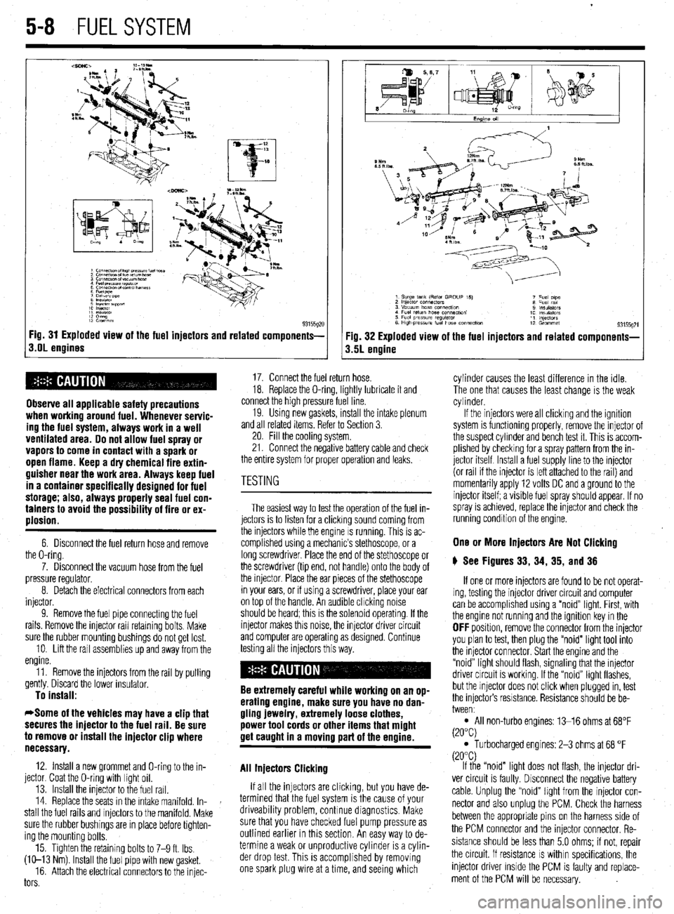
93155gx Fig. 31 Exploded view of the fuel injectors and related components-
s.OL engines
Observe all applicable safety precautions
when working around fuel. Whenever servic-
ing the fuel system, always work in a well
ventilated area. Do not allow fuel spray or
vapors to come in contact with a spark or
open flame. Keep a dry chemical fire extin-
guisher near the work area. Always keep fuel
in a container specifically designed for fuel
storage; also, always properly seal fuel con-
tainers to avoid the possibility of fire or ex-
plosion.
6. Disconnect the fuel return hose and remove
the O-ring.
7. Disconnect the vacuum hose from the fuel
pressure regulator.
8. Detach the electrical connectors from each
injector.
9. Remove the fuel pipe connectmg the fuel
rails. Remove the injector rail retaining bolts. Make
sure the rubber mounting bushings do not get lost.
10. Lift the rail assemblies up and away from the
engine.
11. Remove the injectors from the rail by pulling
gently. Discard the lower insulator.
To install:
*Some of the vehicles may have a clip that
secures the injector to the fuel rail. Be sure
to remove or install the injector clip where
necessary.
12. Install a new grommet and O-ring to the in-
jector. Coat the O-ring with light oil.
13. Install the injector to the fuel rail.
14. Replace the seats in the intake manifold. In-
stall the fuel rails and injectors to the manifold. Make
sure the rubber bushings are in place before tighten-
ing the mounting bolts.
15. Tighten the retaining bolts to 7-9 ft. Ibs.
(W-13 Nm) Install the fuel pipe with new gasket.
16. Attach the electrical connectors to the injec-
tors
Fig. 32 Exploded view of the fuel injectors and related components-
3.5L engine
17. Connect the fuel return hose.
18. Replace the O-ring, lightly lubricate it and
connect the high pressure fuel line.
19. Usmg new gaskets, install the intake plenum
and all related items. Refer to Section 3.
20. Fill the cooling system.
21. Connect the negative battery cable and check
the entire system for proper operation and leaks.
The easiest way to test the operation of the fuel in-
jectors is to listen for a clicking sound coming from
the injectors while the engine IS running. This is ac-
complished using a mechanic’s stethoscope, or a
long screwdriver. Place the end of the stethoscope or
the screwdriver (tip end, not handle) onto the body of
the injector. Place the ear pieces of the stethoscope
in your ears, or if using a screwdriver, place your ear
on top of the handle. An audible chcking noise
should be heard; this is the solenoid operating. If the
injector makes this noise, the injector driver circuit
and computer are operating as designed. Continue
testing all the injectors this way.
Be extremely careful while working on an op-
erating engine, make sure you have no dan-
gling jewelry, extremely loose clothes,
power tool cords or other items that might
get caught in a moving part of the ermine.
All Injectors Clicking
If all the injectors are clicking, but you have de-
termined that the fuel system is the cause of your
driveability problem, continue diagnostics. Make
sure that you have checked fuel pump pressure as
outlined earlier in this section. An easy way to de-
termine a weak or unproductive cylinder is a cylin-
der drop test. This is accomplished by removing
one spark plug wire at a time, and seeing which cylinder causes the least difference in the idle.
The one that causes the least change is the weak
cylinder.
If the injectors were all clicking and the ignition
system is functioning properly, remove the injector of
the suspect cylinder and bench test it. This is accom-
plished by checking for a spray pattern from the in-
jector itself Install a fuel supply line to the injector
(or rail if the injector is left attached to the rail) and
momentarily apply 12 volts DC and a ground to the
injector itself; a visible fuel spray should appear. If no
spray is achieved, replace the injector and check the
running condition of the engine.
One or More Injectors Are Not Clicking
6 See Figures 33, 34, 35, and 36
If one or more injectors are found to be not operat-
ing, testing the injector driver circuit and computer
can be accomplished using a “noid” light. First, with
the engine not running and the ignition key in the
OFF position, remove the connector from the injector
you plan to test, then plug the “noid” light tool into
the injector connector. Start the engine and the
“noid” light should flash, signaling that the injector
driver circuit is working. If the “noid” light flashes,
but the injector does not click when plugged in, test
the injectors resistance. Resistance should be be-
tween:
l All non-turbo engines: 13-16 ohms at 68°F
(20°C)
l Turbocharged engines: 2-3 ohms at 68 “F
(20°C)
If the “noid” light does not flash, the injector dri-
ver circuit is faulty. Disconnect the negative battery
cable. Unplug the “noid” light from the injector con-
nector and also unplug the PCM. Check the harness
between the appropriate pins on the harness side of
the PCM connector and the injector connector. Re-
sistance should be less than 5.0 ohms; if not, repair
the circuit. If resistance
IS within specifications, the
injector driver inside the PCM is faulty and replace-
ment of the PCM will be necessary.
Page 209 of 408
.
6-6 CHASSIS ELECTRICAL
This test already assumes the existence of an open
in the circuit and it is used to help locate the open
portion
1. Isolate the circuit from power and ground.
2. Connect the self-powered test light or ohmme-
ter ground clip to the ground side of the circuit and
probe sections of the circuit sequentially.
3. If the light is out or there is infinite resistance,
the open is between the probe and the circuit ground.
4. If the light is on or the meter shows continuity,
the open is between the probe and the end of the cir-
cuit toward the power source.
SHORT CIRCUITS
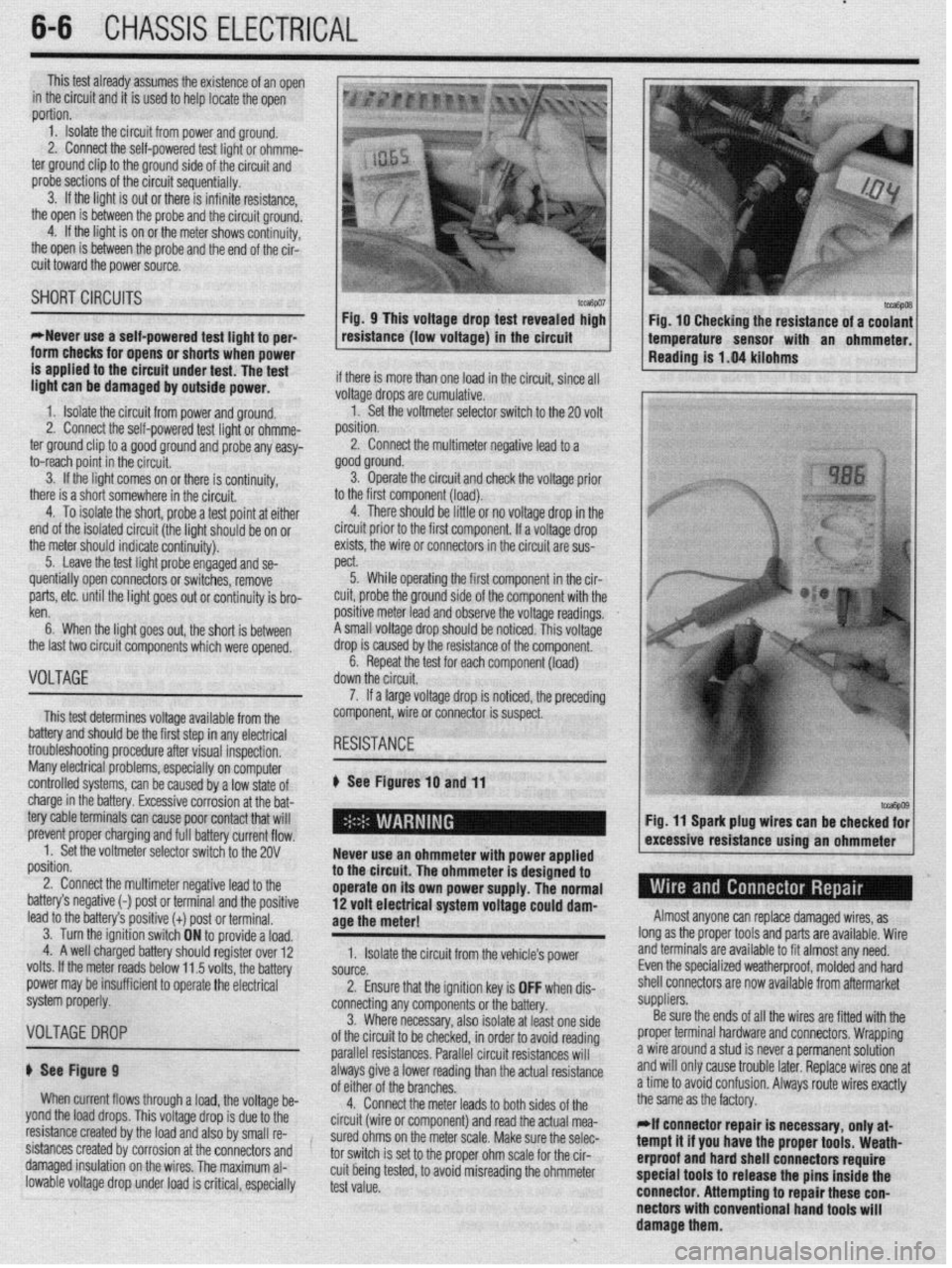
*Never use a self-powered test tight to per-
form checks for opens or shorts when power Fig. 10 Checking the resistance of a coolant
temperature sensor with an ohmmeter.
Reading is 1.04 kilohms
is applied to the circuit under test. The test
linht man he dmn~nsrl hu nutnitls nnuva~ if there is more than one load in the circuit, since all m.3.m. “Y.. “1 “ulll”y”” u, ““..7IYG p”“lz’.
1. Isolate the circuit from power and ground.
2. Connect the self-powered ’ .,.*. ,
ted ugnt or onmme-
ter ground clip to a good ground
and probe any easy-
to-reach point in the circuit.
3. If the light comes on or there is continuity,
there is a short somewhere in the circuit.
4. To isolate the short, probe a test point at either
end of the isolated circuit (the light should be on or
the meter should indicate continuity).
5. Leave the test light probe engaged and se- voltage drops are cumulative.
1. Set the voltmeter selector switch to the 20 volt
^,.^X^..
pJbl1IUII.
2. Connect the multimeter negative lead to a
good ground.
3. Operate the circuit and check the voltage prior
.
to the hrst component (load).
4. There should be little or no voltage drop in the
circuit prior to the first component. If a voltage drop
exists, the wire or connectors in the circuit are sus-
WY.+
)JGW 5. While operating the first component in the cir-
.
positive meter lead and observe the voltage readings.
A small voltage drop should be noticed. This voltage
drop is caused by the resistance of the component.
6. Repeat the test for each component (load)
de .-IL- .‘.. .I
uuwn me crrcun. quentially open connectors or switches, remove
parts, etc. until the light goes out or continuity is bro-
ken
6. When the light goes out, the short is between
the last two circuit components which were opened,
nl -r*l?I-
VuLlHbt
This test determines voltage available from the
battery and should be the first step in any electrical
troubleshooting procedure after visual inspection,
Many electrical problems, esoeciallv on comouter
controlled systems, can be caused by a low state of 7. If a large voltage drop is noticed, the preceding
component, wire or connector is suspect.
# See Figures
10 and 11
charge in the battery. Excessive corrosion at the bat-
tery cable terminals can cause poor contact that will
prevent proper charging and full battery current flow,
1. Set the voltmeter selector switch to the 20V
position.
2. Connect the multimeter negative lead to the
h*+tnn,‘n nnn,,,;~,,. , ..^,a ^-L.--:^^l --_I ‘I- ---!I?... Never use an ohmmeter with power applied
to the circuit. The ohmmeter is designed to
operate on its 0 wn power supply. The normal
1^
. . . . . Fig. 11 Spark plug wires can be checke;
MW~ 3 IlG~dllYt: t-1 pUSI UI Lellllllldl allU lilt, pUSlIlVe lead to the battery’s positive (t) post or terminal.
3. Turn the ignition switch ON to provide a load,
4. A well charged battery should register over 12
volts. If the meter reads below 11 5 vnlts tha hq*anr
_ _ .-, . power may be insufficient to operate the eler ii! volt electrical system voltage could dam-
age the meter!
1. Isolate the circuit from the vehicle’s power
CnlOrAn I)““IW. 2. Ensure that the ignition key is OFF when dis- Almost anyone can replace damaged wires, as
long as the proper tools and parts are available. Wire
and terminals are available to fit almost any need.
Even the specialized weatherproof, molded and hard
shell connectors are now cl mdicm available from aftermarket
system properly.
connecting any components or the battery. ““yp,8w’“.
3. Where necessary, also isolate at least one side Be sure the ends of all the wires are fitted with the
VOLTAGEDROP of the circuit to be checked, in order to avoid reading proper terminal hardware and connectors. Wrapping
parallel resistances. Parallel circuit resistances will a wire around a stud is never a permanent solution
# See Figure 9 always give a lower reading than the actual resistance and will only cause trouble later. Replace wires one at
When current flows through a load, the voltage be- of eifhy n< +hn hmnnh-r
GI “I II It: “I a lb1 It?>. a time to avoid confusion. Always route wires exactly
4.
Connect the meter leads to both sides of the the same as the factory.
yond the load drops. This voltage drop is due to the
resistance created by the load and also by small re- circuit (wire or component) and read the actual mea-
sured ohms on the meter scale. Make sure the selec- *If connector repair is necessary, only at-
sistances created by corrosion at the connectors and
tor switch is set to the proper ohm scale for the cir- tempt it if you have the proper tools. Weath-
damaged insulation on the wires. The maximum al- erproof and hard shell connectors require
lowable voltage drop under load is critical, especially cuit being tested, to avoid misreading the ohmmeter
test value. spectal tools to release the pins inside the
connector. Attempting to repair these con-
nectors with conventional hand tools will
damage them.
Page 210 of 408
I I
CHASSIS ELECTRICAL 6-7
When working on any electrical component on the
vehicle, it is always a good idea to disconnect the
negative (-) battery cable. This will prevent potential
damage to many sensitive electrical components
such as the Powertrain Control Module (PCM), radio,
alternator, etc.
*Any time you disengage the battery cables,
it is recommended that you disconnect the negative (-) battery cable first. This will pre-
vent your accidentally grounding the positive
(+) terminal to the body of the vehicle when
disconnecting it, thereby preventing damage
to the above mentioned components.
Before you disconnect the cable(s), first turn the
ignition to the OFF position. This will prevent a draw
on the battery which could cause arcing (electricity
trying to ground itself to the body of a vehicle, just
like a spark plug jumping the gap) and, of course, damaging some components such as the alternator
diodes.
When the battery cable(s) are reconnected (nega-
tive cable last), be sure to check that your lights,
windshield wipers and other electrically operated
safety components are all working correctly. If your
vehicle contains an Electronically Tuned Radio (ETR),
don’t forget to also reset your radio stations. Ditto for
the clock.
SERVICE PRECAUTIONS
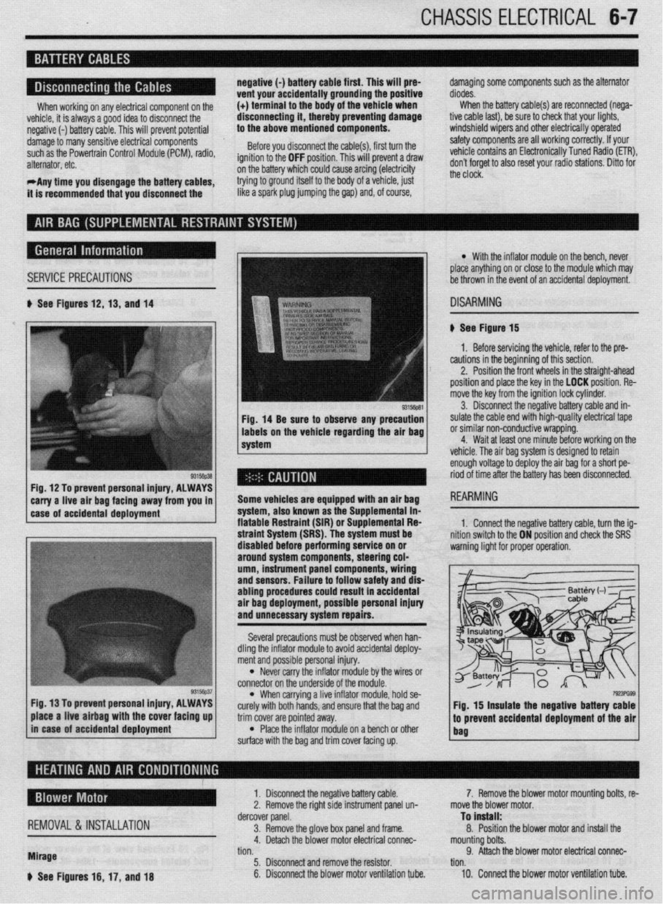
b See Figures 12,13, and 14
Fig, 14 Be sure to observe any precaution
labels on the vehicle regarding the air bag
system
Fig. 12 To prevent personal injury, ALWAYS
*
carry a-live -ah bag fac!ng away from you in 1
1 case of accidental deployment Some vehicles are equipped wtth an air bag
-.-‘--
syr1em, aiscl Known as I11 -I-- ‘------- -- sLe Supplemental in- fiatable Restraint (SIR) o r Suouiementai Fiea
l With the inflator module on the bench, never
place anything on or close to the module which may
be thrown in the event of an accidental deployment.
DISARMING
# See Figure 15
1. Before servicing the vehicle, refer to the pre-
cautions in the beginning of this section.
2. Position the front wheels in the straight-ahead
position and place the key in the LOCK position. Re-
move the key from the ignition lock cylinder.
3. Disconnect the negative battery cable and in-
sulate the cable end with high-quality electrical tape
or similar non-conductive wrapping.
4. Wait at least one minute before working on the
vehicle. The air baa svstem is desianed to retain
enough voltage to deploy the air bag for a short pe-
riod of time after the battery has been disconnected.
1. Connect the neoative batters cable. turn the ia-
3, hold se-
e bag and
trim cover are pointed away.
l Place the inflator module on a bench or other
surface with the bag and trim cover facing up.
7!r!3PG93 Fig. 15 insulate the negative battery cable
.I
to prevent accidental deployment of the air
bag place a live airbag with the cover facing up
in case of accidental deployment
REMOVAL &INSTALLATION
Mirage
b See Figures 16, 17, and 18 1. Disconnect the negative battery cable.
2. Remove the right side instrument panel un-
dercover panel.
3. Remove the glove box panel and frame.
4. Detach the blower motor electrical connec-
tion.
5. Disconnect and remove the resistor.
6. Disconnect the blower motor ventilation tube. 7. Remove the blower motor mounting bolts, re-
move the blower motor.
To install:
8. Position the blower motor and install the
mounting bolts.
9. Attach the blower motor electrical connec-
tion.
10. Connect the blower motor ventilation tube.
Page 232 of 408
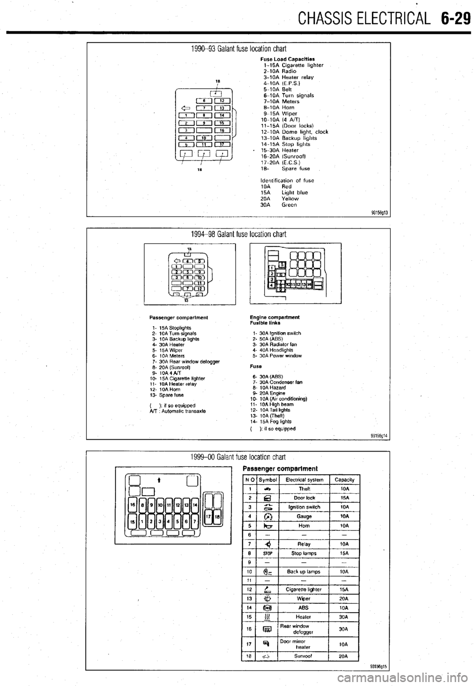
CHASSIS ELECTRlCiL 6-29
1990-93 Galant fuse location chart Fuse Load Capacities
l-15A Cigarette hghter
Z-10A Radm
3-10A Heater relay
4-10A (E P S.)
5-10A Belt
6-10A Turn signals
7-10A Meters
6-10A Horn
9-15A Wiper
lo-10A (4 A/T)
ll-15A (Door locks)
12-10A Dome hght, clock
13-10A Backup hghts
14-15A Stop hghts
15-30A Heater
16m20A (Sunroof)
17-20A (ECS)
1% spare fuse
ldentlfxation of fuse
10A Red
15A Light blue
20A Yellow
30A Green
93156g13
1994-98 Galant fuse location chart
Passenger compartment
1. 15A StoplIghts
2- 10A Turn signals
3- 1 OA Backup Itghts
4. 30A Heater
5. i5A Wiper
6- IOA Meters
7. 30A Rear wndow defogger
;: fo& fl$oof)
IO- 15A Cagaretle lighler
11. 10A Heater relay
12. IOA Horn
13. Spare fuse
( ): II so equipped
A!T Automallc transaxle Engine compartment
Fusible links
I- 30A Ignition swlch
2. 50A (ABS)
3. 30A Radiator fan
4. 40A Headkghts
5. 30A Power wndow
Fuse
6- 30A (ABS)
7. 30A Condenser fan
6. 10A Hazard
9. 20A Engine
10. 10A (Au conditioning)
11. 10AHigh beam
12. 10ATall lkghts
13. 10A (Theft)
14. i5A Fog lkghls
( ): If so equipped
93156g14
1999-00 Galant fuse location chart
Page 239 of 408
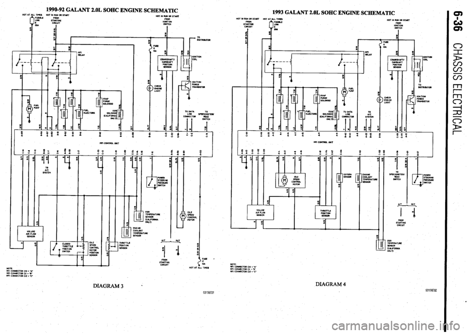
1990-92 GALANT 2.OL SOHC ENGINE SCHEMATIC
1993 GALANT 2.OL SOHC ENGINE SCHEMATIC HOT IN RIB aR START
STEki
CIRCUT HOTINRWORSTART
FROH
16NlTlON
SWITCH
t HOT IN RUR OR STlRT
HOT AT ALL TIMES
HOT IN RU4 DR START
FRDtl
IGNITION
SWITCH
I EEE LIGHT
! a
s ;
--
T m
> CHECK
EN6lNE
LIGHT
%
i E IGNITION
PDWER
4 ’
TRANSISTOR
D
4
&Rl,DR
s
ICNlTlOK
FUWER
TRARSlSTOR
m
TO OATA
LINK SPEED&TEfl/
CONRECTM
REED
( !iWlTCH TO
UC
WI CWJTROL UNIT
IDLE
> SFEED
CONTROL
MOTOR AIT
! n/T.
I 1 0
1
STEK
ClRCUT EGR
TEnFERA~
SENSOR
mLIFoRRlA
WLn
VOLUME
AIR FLOW
SENSOR
I
5
E
! %
FUSE *
I7
IOA
HOT AT ALL TIMES EGR
TEMFERATLRE
SERSDR
, (~~IFORR~A
ONLV) An L MT
.
B m
11
STARTING
CIRCUT NOTE
I’IFI CORRECTOR Cl0 = -A-
WI coRNEcmR CII - 3’
“FI CONNECTOR Cl2 I 77
DIAGRAM 4 93156E02
NOlE
MFI CCMECTOR Cl0 = ‘A-
WI CONNECTOR Cl, = %’
WI CDNNECTOR Cl2 = C
DIAGRAM3 l 93156EOl