1900 MITSUBISHI DIAMANTE ignition
[x] Cancel search: ignitionPage 87 of 408
3-26 ENGINEANDENGINEOVERHAUL
18. Remove the self-locking nuts and the small
retaining bolt holding the exhaust pipe to the bottom
of the exhaust manifold. Separate the pipe from the
manifold and remove the gasket.
19. Remove the bolts holding the support brace
to the bottom of the intake manifold.
20. Use the special hex wrench (MB 998051-01)
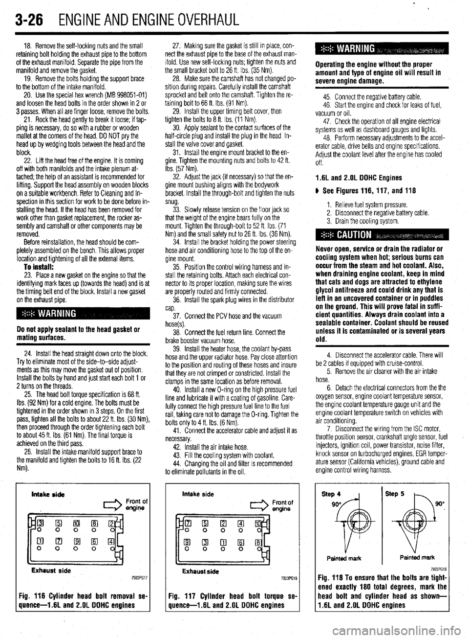
and loosen the head bolts in the order shown in 2 or
3 passes. When all are finger loose, remove the bolts.
21. Rock the head gently to break it loose; if tap-
ping is necessary, do so with a rubber or wooden
mallet at the corners of the head. DO NOT pry the
head up by wedging tools between the head and the
block.
22. Lift the head free of the engine. It is coming
off with both manifolds and the intake plenum at-
tached; the help of an assistant is recommended for
lifting. Support the head assembly on wooden blocks
on a suitable workbench. Refer to Cleaning and In-
spection in this section for work to be done before in-
stalling the head. If the head has been removed for
work other than gasket replacement, the rocker as-
sembly and camshaft or other components may be
removed.
Before reinstallation, the head should be com-
pletely assembled on the bench. This allows proper
location and tightening of all the external items.
To install: 23. Place a new gasket on the engine so that the
identifying mark faces up (towards the head) and is at
the timing belt end of the block. Install a new gasket
on the exhaust pipe.
Do not apply sealant to the head gasket or
mating surfaces.
24. Install the head straight down onto the block.
Try to eliminate most of the side-to-side adjust-
ments as this may move the gasket out of position.
Install the bolts by hand and just start each bolt 1 or
2 turns on the threads.
25. The head bolt torque specification is 68 ft.
Ibs. (92 Nm) for a cold engine. The bolts must be
tightened in the order shown in 3 steps. On the first
pass, tighten all the bolts to about 22 ft. Ibs. (30 Nm),
then proceed through the order tightening each bolt
to about 45 ft. Ibs. (61 Nm). The final torque is
achieved on the third pass.
26. Install the intake manifold support brace to
the manifold and tighten the bolts to 16 ft. Ibs. (22
Nm). 27. Making sure the gasket is still in place, con-
nect the exhaust pipe to the base of the exhaust man-
ifold. Use new self-locking nuts; tighten the nuts and
the small bracket bolt to 26 ft. Ibs. (35 Nm).
28. Make sure the camshaft has not changed po-
sition during repalrs. Carefully install the camshaft
sprocket and belt onto the camshaft. Tighten the re-
taining bolt to 66 ft. Ibs. (91 Nm).
29. Install the upper timing belt cover, then
tighten the bolts to 8 ft. Ibs. (11 Nm).
30. Apply sealant to the contact surfaces of the
half-circle plug and install the plug in the head In-
stall the valve cover and gasket.
31. Install the engine mount bracket to the en-
gine. Tighten the mounting nuts and bolts to 42 ft.
Ibs. (57 Nm).
32. Adjust the jack (if necessary) so that the en-
gine mount bushing aligns with the bodywork
bracket. Install the through-bolt and tighten the nuts
snug.
33. Slowly release tension on the floor jack so
that the weight of the engine bears fully on the
mount. Tighten the through-bolt to 52 ft. Ibs. (71
Nm) and the small safety nut to 26 ft. tbs. (36 Nm).
34. Install the bracket holding the power steering
hose and air conditioning hose to the top of the en-
gine mount.
35. Position the control wiring harness and in-
stall the retaining bolts. Attach each electrical con-
nector to its proper location, making sure the wires
are properly routed and firmly connected.
36. Install the spark plug wires in the distributor
cap.
37. Connect the PCV hose and the vacuum
hose(s).
38. Connect the fuel return line. Connect the
brake booster vacuum hose.
39. Install the heater hose, the coolant by-pass
hose and.the upper radiator hose. Pay close attention
to the position and routing of these hoses and insure
that they are not crimped or constricted. Install the
clamps in the same location as before removal.
40. Install a new O-ring on the high pressure fuel
line and lubricate it with a coating of gasoline. Care-
fully connect the high pressure fuel line to the fuel
rail, taking care not to damage the O-ring. Tighten the
bolts only to 4 ft. Ibs. (6 Nm).
41. Connect the accelerator cable and adjust it as
necessary.
42. Install the air intake hose.
43. Fill the cooling system with coolant.
44. Changing the oil and filter is recommended
to eliminate pollutants in the oil.
Intake side
I Front of
engine
Exhaust side
Fig. 116 Cylinder head bolt removal se-
quence-l .6L and 2.OL DDHC engines intake
side
Front of
entine
Exhaust side 7923PG18
Fig. 117 Cylinder head bolt torque se-
quence-l .6L and 2.OL DDHC engines Operating the engine without the proper
amount and type of engine oil will result in
severe engine damage.
45. Connect the negative battery cable.
46. Start the engine and check for leaks of fuel,
vacuum or oil.
47. Check the operation of all engine electrical
systems as well as dashboard gauges and lights.
48. Perform necessary adjustments to the accel-
erator cable, drive belts and engine specifications.
Adjust the coolant level after the engine has cooled
Off.
1.6L and 2.OL DDHC Engines
ti See Figures 116,117, and 116
1. Relieve fuel system pressure.
2. Disconnect the negative battery cable.
3. Drain the cooling system.
Never open, service or drain the radiator or
cooling system when hot; serious burns can
occur from the steam and hot coolant. Also,
when draining engine coolant, keep in mind
that cats and dogs are attracted to ethylene
glycol antifreeze and could drink any that is
left in an uncovered container or in puddles
on the ground. This will prove fatal in suffi-
cient quantities. Always drain coolant into a
sealable container. Coolant should be reused
unless it is contaminated or is several years
old.
4. Disconnect the accelerator cable. There will
be 2 cables if equipped with cruise-control.
5. Remove the air cleaner with the air intake
hose.
6. Detach the electrical connectors from the the
oxygen sensor, engine coolant temperature sensor,
the engine coolant temperature gauge unit and the
engine coolant temperature switch on vehicles with
air conditioning.
7. Disconnect the wiring from the ISC motor,
throttle position sensor, crankshaft angle sensor, fuel
injectors, ignition coil, power transistor, noise filter,
knock sensor on turbocharged engines, EGR temper-
ature sensor (California vehicles), ground cable and
engine control wiring harness.
Painted mark Painted mark
Fig. 116 To ensure that the bolts are tight-
ened exactly 160 total degrees, mark the
11.6L and 2.OL DDHC engines head bolt and cylinder head as shown-
Page 88 of 408
ENGlNEANDENGlNEOVERHALiL 3-27
8. Remove the upper radiator hose and the
sages thoroughly. Check the head for flatness. End to 31. Install the air cleaner and intake hose. Con-
overflow tube. end, the head should be within 0.002 in. (0.05mm) nect the breather hose.
9. Remove the spark plug cable center cover,
normally, with 0.008 in. (0.2mm) the maximum al- 32. Change the engine oil and oil filter,
then remove the spark plug cables.
lowed out of true. The total thickness allowed to be 33. Fill the system with coolant.
10. Disconnect and plug the high pressure fuel
removed from the head and block is 0.008 in.
line. 34. Connect the negative battery cable.
(0.2mm) maximum. 35. Run the vehicle until the thermostat opens,
11. Disconnect the small vacuum hoses.
23. Place a new head gasket on the cylinder and fill the radiator completely.
12. Remove the heater hose and water bypass
block with the identification marks at the front top 36. Check and adjust the idle speed and ignition
hose.
(upward) position. Make sure the gasket has the timing.
13. Remove the PCV hose.
proper identification mark for the engine. Do not use 37. Once the vehicle has cooled, recheck the
14. If turbocharged, remove the vacuum hoses,
sealer on the gasket. Replace the turbo gasket and coolant level.
water line and eyebolt connection for the oil line for
ring, if equipped.
the turbo.
24. Carefully install the cylinder head on the 2.41 Engine
15. Disconnect and plug the fuel return hose. block. Using 3 even steps, torque the head bolts, in
16. Disconnect the brake booster vacuum hose.
sequence, to 65-72 ft. Ibs. (90-100 Nm). This torque b See Figures 119 thru 131
17. Remove the timing belt. applies to a cold engine. If checking cylinder head
18. Remove the valve cover and the half-round
bolt torque on hot engine, the desired specification is 1. Relieve the fuel system pressure.
seal.
7240 ft. Ibs. (100-110 Nm). 2. Disconnect the negative battery cable.
19. On non-turbocharged engines, remove the 3. Remove the air cleaner with all air intake
25. On turbocharged engine, install the heat
hoses.
exhaust pipe self-locking nuts and separate the ex-
shield. On non-turbocharged engines, install a new
haust pipe from the exhaust manifold. Discard the
exhaust pipe gasket and connect the exhaust pipe to 4. Drain the cooling system.
gasket.
the manifold.
20. On turbocharged engines, remove the sheet
26. Apply sealer to the perimeter of the half-
metal heat protector and remove the bolts that attach
round seal and to the lower edges of the half-round Never open, service or drain the radiator or
the turbocharger to the exhaust manifold.
portions of the belt-side of the new gasket. Install the cooling system when hot; serious burns can
21. Loosen the cylinder head mounting bolts in 3
valve cover. occur from the steam and hot coolant. Also,
steps, starting from the outside and working inward,
27. Install the timing belt and all related items. when draining engine coolant, keep in mind
Lift off the cylinder head assembly and remove the
28. Connect or install all previously disconnected that cats and dogs are attracted to ethylene
n head gasket.
hoses, cables and electrical connections. Adjust the glycol antifreeze and could drink any that is
To install:
throttle cable(s). left in an uncovered container or in puddles
22. Thoroughly clean and dry the mating surfaces
29. Install the spark plug cable center cover. on the ground. This will prove fatal in suffi-
of the head and block. Check the cylinder head for
30. Replace the O-rings and connect the fuel eient quantities. Always drain coolant into a
cracks, damage or engine coolant leakage. Remove
lines. sealable container. Coolant should be reused
scale, sealing compound and carbon. Clean oil pas- unless it is contaminated or is several years
old.
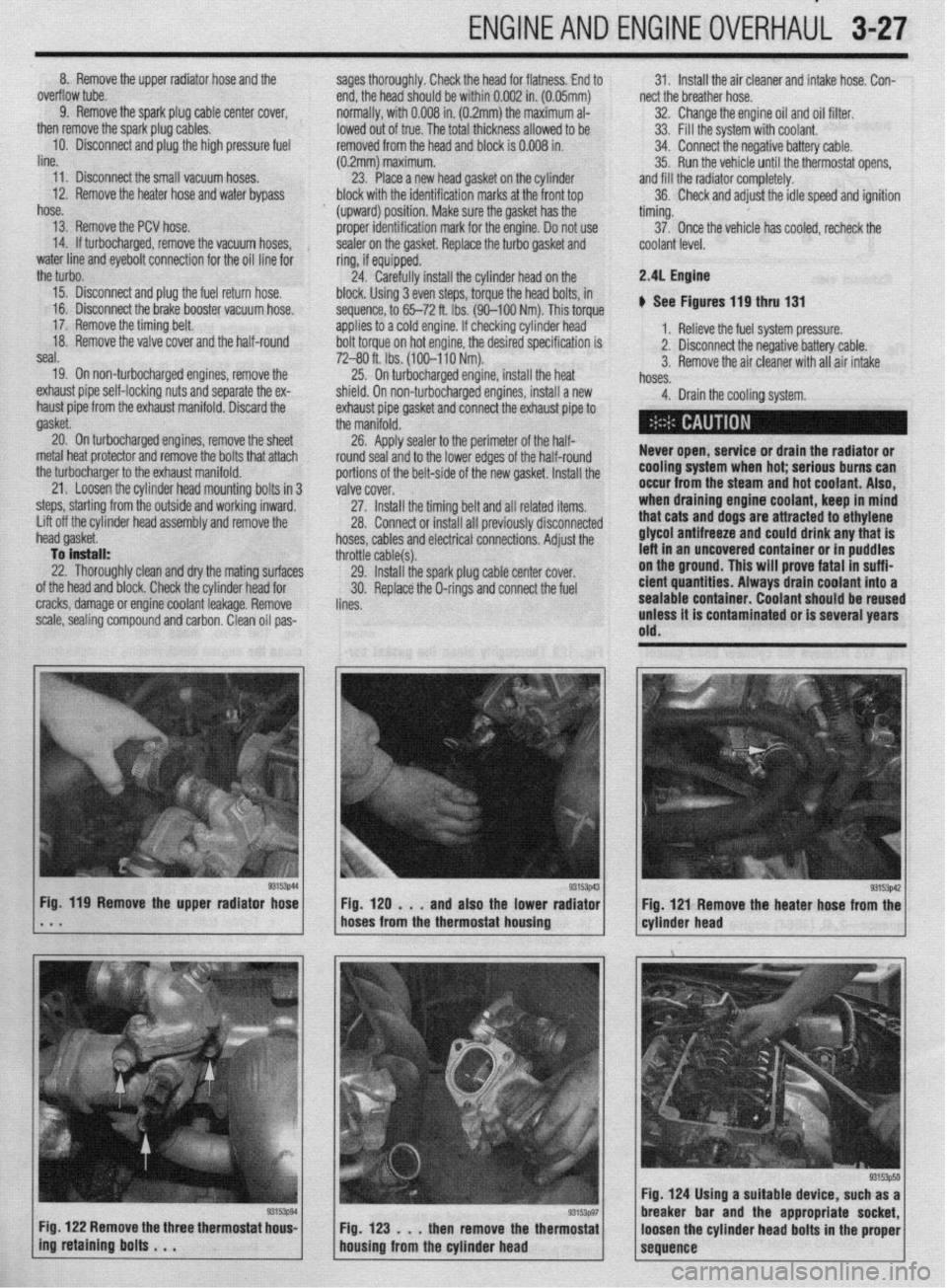
g3153p44 Fig. 119 Remove the upper radiator hose
* . . 1 Fig. 129 . . . and also the lower rad:gzi / cyl.der head g3153W
Fig 121 Remove the heater hose from the
hoses from the thermostat housing
Fig. 122 Remove the three thermostat hous-
Fig. 123 . . . then remove the thermostat
ing retaining bolts . . .
housing from the cylinder head
93153p50 Fig. 124 Using a suitable device, such as a
breaker bar and the appropriate socket,
loosen the cylinder head bolts in the proper
sequence
Page 89 of 408
3-28 ENGINEANDENGINEOVERHAUL
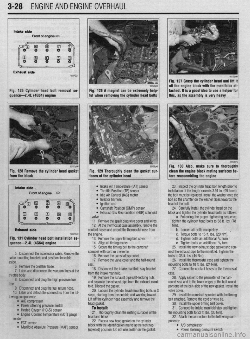
lntsltaelde Front of engine c3
Fig. 125 Cylinder head bolt removal se- Fig. 127 Grasp the cylinder head and lift it
off the engine block with the manifolds at-
ig. 126 A magnet can be extremely help- tached. It is a good idea to use a helper for
quence-2.41(4664) engine I ful when removing the cylinder head bolts 1 1 this, as the assembly is very heavy
93153pOO Fig. 128 Remove the cylinder head gasket 33153p4!3 Fig, 129 Thoroughly clean the gasket sur- Fig. 130 Also, make sure to thoroughly
clean the engine block mating surfaces be-
from the block
faces of the cylinder head fore reassembling the engine
l Intake Air Temperature (IAT) sensor l Throttle Position (TP) sensor
: /I;%;,; rZ;Z;;(lAC) motor 23. Inspect the cylinder head bolt length prior to
installation. If the length exceeds 3.91 in. (99.4mm),
the bolt must be replaced. Install the washer onto the
bolt so the chamfer on the washer faces towards the
l Ignition coil head of the bolt. l Camshaft Position (CMP) sensor 24. Carefully install the cylinder head on the l Exhaust Gas Recirculation (EGR) solenoid block and tighten the cylinder head bolts as follows:
valve a. Following the proper tightening sequence,
11. Remove the spark plug wire cover and wires. tighten the cylinder head bolts to 58 ft. Ibs. (78
12. At the thermostat case assembly, remove the Nm).
coolant hoses and unbolt the thermostat case from b. Loosen all bolts completely.
the engine. c. Torque bolts to 15 ft. Ibs. (20 Nm). ’
Fig. 131 Cylinder head bolt installation se-
13. Remove the upper timing belt cover d. Tighten bolts an additional 1/4 turn.
14. Align all timing marks. e. Tighten bolts an additional 1/4 turn.
15. Secure the timina belt to the camshaft 25. Install the new exhaust pipe aasket and con-
iliiL.-
5.
9. Disconnect and plug the fuel return hose. Disconnect the accelerator cable. Remove the
cable mounting brackets and position the cable
10. Label and detach the connectors from the fol- aside.
lowing components: 6. Remove the breather hose.
* A$ compressor
* Power steering pressure switch ‘7. Label and disconnect the vacuum lines at the
* Heated Oxygen (HO$) sensor tree body.
* Engine Coolant Temperature (ECT) gauge . 8. D&connect and plug the high pressure fuel
sender
lint3
l
ECT sensor l Manifold Absolute Pressure (MAP) sensor sprocket with cord or a wire tie.
fold. Discard the gasket, 16. Remove the camshaft sprocket.
20. Loosen the cylinder head mounting bolts in 3 17.
steps, starting from the outside and working inward. Remove the valve cover and the half-round
seal.
Lift off the cylinder head assembly and remove the 18. Disconnect the intake manifold stay bracket
head gasket.
To install: from the intake manifold.
21. Thoroughly clean the mating surfaces of the 19. Remove the exhaust pipe self-locking nuts
head and block. and separate the exhaust pipe from the exhaust mani-
22. Place a new head gasket on the cylinder
block with the identification marks at the front top
(upward) position. Do not use sealer on the gasket. nect the exhaust pipe to the manifold. Tighten the
portions of the belt-side of the new gasket. Install thr bolts to 33 ft. Ibs. (44 Nm).
valve cover. 26.
29. Install the thermostat case and tighten the
Install the camshaft sprocket with the timing mounting bolts to 18 ft. Ibs. (24 Nm).
belt attached. Remove the cord or wire tie.
30. Install the upper timing belt cover. 27. Connect the coolant hoses to the thermostat
31. Connect the intake manifold stay and tighten case.
the mounting bolts to 22 ft. Ibs. (30 Nm). 28.
32. Attach the connectors to the following com- Apply sealer to the perimeter of the half-
round seal and to the lower edges of the half-round
ponents: l A/C compressor l Power steering pressure switch
Page 90 of 408
ENGINEANDENGINEOVERHAUL 3-29
l HOzS sensor l ECT gauge sender l ECT sensor l MAP sensor l IAT sensor l TP sensor l IAC motor l injector harness l ignition coil l CMP sensor l EGR solenoid valve
33. Install the spark plug wires and cover,
34. Replace the O-rings and connect the fuel
lines.
35. Install the air cleaner and intake hose. Con-
nect the breather hose.
36. Fill the cooling system.
37. Connect the negative battery cable
3.01 DDHC Engine
ti See Figures 132 and 133
1. Relieve fuel system pressure. Disconnect the
negative battery cable.
2. Drain the cooling system.
Never open, service or drain the radiator or
cooling system when hot; serious burns can
occur from the steam and hot coolant. Also,
when draining engine coolant, keep in mind
that cats and dogs are attracted to ethylene
glycol antifreeze and could drink any that is
left in an uncovered container or in puddles
on the ground. This will prove fatal in suffi-
cient quantltles. Always drain coolant into a
sealable container. Coolant should be reused
unless it is contaminated or is several years
old.
3. Remove the air intake hoses.
4. Remove air intake plenum and intake mani-
fold.
5. Remove the exhaust manifold.
6. Remove the timing belt. Refer to the timing
belt procedure in this section.
7. Remove the breather hose.
8. Remove the spark plug wire center cover and
remove the spark plug wires.
9. Remove the rocker covers.
10. Remove the intake camshaft sprockets.
11. Remove the rear timing belt cover.
12. Remove the ignition coil assembly.
13. Disconnect all water hoses from the thermo-
stat housing and remove the housing.
14. Disconnect the water inlet from the front
head.
15. Loosen the cylinder head mounting bolts in
the reverse of the torque sequence and loosen the
bolts in three steps. Lift off the cylinder head assem-
bly and remove the head gasket.
To install: 16. Thoroughly clean the sealing surfaces of the
head and block.
17. Place a new head gasket on the cylinder
block with the identification marks in the front top
(upward) position. Do not use sealer on the gasket,
18. Carefully install the cylinder head on the
block. Be sure the head bolt washers are installed
with the chamfered edge upward. Using three even
steps, torque the head bolts in sequence, to 76-83 ft.
Ibs. (105-115 Nm).
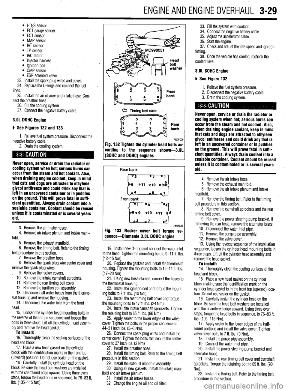
@ Timing belt side
7923PG26 :ig. 132 Tighten the cylinder head bolts ac-
:ording to the sequence shown-3.01
SDHC and DDHC) engines
Rear bank
[::od
04
~8 01
Front bank
'1 "8
509 010 011 6
1.03 07 02 7923ffi25 Fig. 133 Rocker cover bolt torque se-
quence-Diamante 3.OL DDHC engine
19. Install new O-ring and connect the water inlet
to the head. Tighten the mounting bolt to 9-11 ft. Ibs
(12-15 Nm).
20. Replace the gaskets and install the thermostat
housing. Tighten the mounting bolts to 12-14 ft. Ibs.
(17-20 Nm).
21. Using new hose clamps, connect the hoses to
the thermostat housing.
22. Install the Ignition coil and torque the mount-
ing bolts to 7 ft. Ibs. (10 Nm).
23. Install the rear timing belt cover and torque
the mounting bolts to 17 ft. Ibs. (24 Nm).
24. Install the intake camshaft sprockets. Tighten
the retaining bolt to 65 ft. Ibs. (90 Nm).
25. Apply sealer to the lower edges of the valve
cover. Tighten the bolts in the proper sequence to
44-51 inch Ibs. (5-6 Nm).
26. Connect the spark plug wires and install the
center cover. Tighten the bolts that secure the center
cover to 27 inch Ibs. (3 Nm)
27. Install the breather hose.
28. Install the timing belt. Refer to the timing belt
procedure in this section,
29. Install the exhaust manifold assembly.
30. Using all new gaskets, install the intake man-
ifold and air intake plenum.
31. Install the air intake hoses.
32. Change the engine oil and oil filter. 33. Fill the system wrth coolant.
34. Connect the negabve battery cable.
35. Adjust the accelerator cable.
36. Start the engine.
37. Check and adjust the idle speed and ignition
timing.
38. Once the vehicle has cooled, recheck the
coolant level.
3.OL SDHC Engine
# See Figure 132
1. Relieve the fuel system pressure.
2. Disconnect the negative battery cable.
3. Drain the cooling system.
Never open, service or drain the radiator or
cooling system when hot; serious burns can
occur from the steam and hot coolant. Also,
when draining engine coolant, keep in mind
that cats and dogs are attracted to ethylene
alvcol antifreeze and could drink any that is
Left in an uncovered container or in puddles
on the ground. This will Drove fatal in suff i-
cient quantities. Always drain coolant into a
sealable container. Coolant should be reused
Unless it is Contaminated or is several years
old.
4. Remove the air intake hose.
5. Remove the exhaust manifold.
6. Remove the air intake plenum and intake
manifold.
7. Remove the timing belt. Refer to the timing
belt procedure in this section.
8. Remove the camshaft sprockets and the rear
timing belt cover.
9. Remove the power steering pump bracket. If
removing the rear head, remove the alternator brace.
10. Disconnect the water inlet pipe.
11. Remove the purge pipe assembly.
12. Remove the valve cover,
13. Using the reverse sequence of the installation
sequence, loosen the cylinder head mounting bolts in
three steps. Lift off the cylmder head assembly and
remove the head gasket.
To install: 14. Thoroughly clean the sealing surfaces of the
head and block.
15. Place a new head gasket on the cylinder
block making sure the identification mark on the
cylrnder head gasket is in the front top (upward) loca-
tion. Do not use sealer on the gasket,
16. Carefully install the cylinder head on the
block. Be sure the head bolt washers are installed
with the chamfered edge upward. Using three even
steps, torque the head bolts in sequence, to 7683 ft.
Ibs. (105-115 Nm).
17. Apply sealer to the lower edges of the half-
round portions and install the valve cover. Tighten
valve cover bolts to 7 ft. Ibs. (9 Nm).
18. Install the purge pipe assembly.
19. Connect the water inlet pipe.
20. Install the power steering pump bracket and
alternator brace.
21. Install the rear timing belt cover and camshaft
sprockets. Torque the retaining bolt to 65 ft. Ibs. (90
Nm).
22. Install the timing belt. Refer to the timing belt
procedure in this section.
Page 91 of 408
.
3-30 ENGINEANDENGINEOVERHAUL
23. Using all new gaskets, install the intake man-
ifold, air intake plenum and exhaust manifold.
24. Install the air intake hose.
25. Fill the system with coolant.
26. Connect the negative battery cable.
27. Start the engine.
28. Check and adjust the idle speed and ignition
timing.
29. Once the vehicle has cooled, recheck the
coolant level.
3.51 Engine
ti See Figure 134
1. Disconnect the negative battery cable.
2. Drain the engine coolant
Never open, service or drain the radiator or
cooling system when hot; serious burns can
occur from the steam and hot coolant. Also,
when draining engine coolant, keep in mind
that cats and dogs are attracted to ethylene
glycol antifreeze and could drink any that is
left in an uncovered container or in puddles
on the ground. This will prove fatal in suffi-
cient quantities. Always drain coolant into a
sealable container. Coolant should be reused
unless it is contaminated or is several years
old.
3. Remove the timing belt. Refer to the timing
belt procedure in this section.
4. Remove the intake and exhaust manifolds.
5. Remove the spark plug wires.
6. Remove the cylrnder head covers.
7. Remove the timing belt rear center cover.
8. Loosen the cylinder head bolts gradually in
three stages, in the opposite of the installation se-
quence.
9. Remove the cylinder head.
To install: 10. Clean the cylinder head and mounting sur-’
face on the engine block.
11. Install the cylinder head using a new gasket.
12. Tighten the bolts in sequence using three
stages to 76-83 ft. Ibs. (103-113 Nm).
13. Install the timing belt rear center cover.
14. Install the cylinder head covers using new
gaskets. Tighten the bolts to 2-3 ft. Ibs. (334 Nm).
15. Install the spark plug wires,
16. Install the intake and exhaust manifolds,
17. Install the timing belt. Refer to the timing belt
procedure in this section.
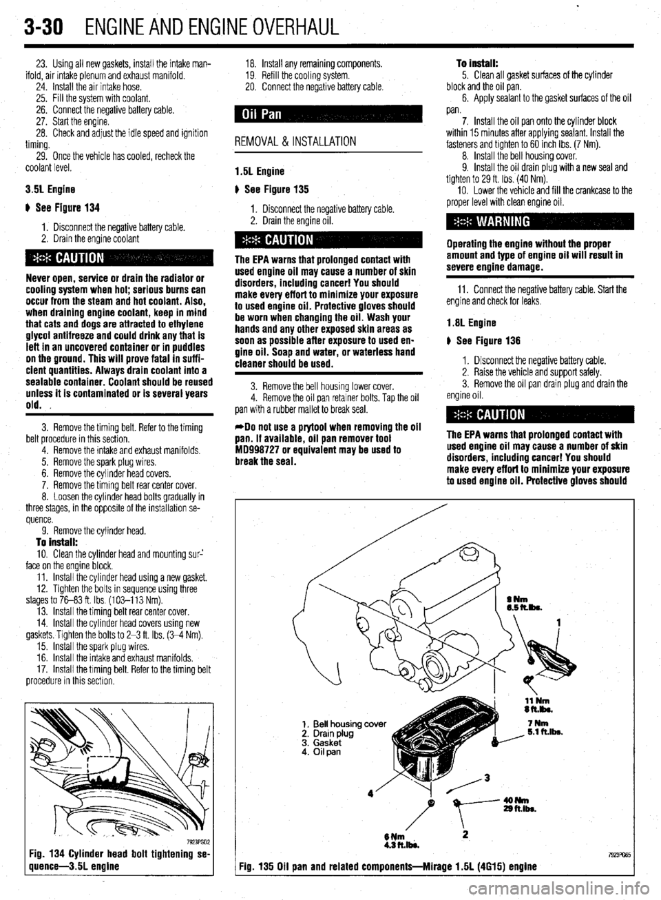
7923PGD2 Fig. 134 Cylinder head bolt tightening se-
quence-3.5L engine
18. Install any remaining components.
19. Refill the cooling system.
20. Connect the negative battery cable.
REMOVAL &INSTALLATION
1.5L Engine
p See Figure 135
1. Disconnect the negative battery cable.
2. Drain the engine oil.
The EPA warns that prolonged contact with
used engine oil may cause a number of skin
disorders, including cancer! You should
make every effort to minimize your exposure
to used engine oil. Protective gloves should
be worn when changing the oil. Wash your
hands and any other exposed skin areas as
soon as possible after exposure to used en-
gine oil. Soap and water, or waterless hand
cleaner should be used.
3. Remove the bell housing lower cover.
4. Remove the oil pan retainer bolts. Tap the oil
pan with a rubber mallet to break seal.
*Do not use a prytool when removing the oil
pan. If available, oil pan remover tool
MD998727 or equivalent may be used to
break the seal. To install:
5. Clean all gasket surfaces of the cylinder
block and the oil pan.
6. Apply sealant to the gasket surfaces of the oil
pan.
7. Install the oil pan onto the cylinder block
within 15 minutes after applying sealant. Install the
fasteners and tighten to 60 inch Ibs. (7 Nm).
8. Install the bell housing cover.
9. Install the oil drain plug with a new seal and
tighten to 29 ft. Ibs. (40 Nm).
10. Lower the vehicle and fill the crankcase to the
proper level with clean engine oil.
Operating the engine without the proper
amount and type of engine oil will result in
severe engine damage.
11. Connect the negative battery cable. Start the
engine and check for leaks.
1.8L Engine
# See Figure 136
1. Disconnect the negative battery cable.
2. Raise the vehicle and support safely.
3. Remove the oil pan drain plug and drain the
engine oil.
The EPA warns that prolonged contact with
used engine oil may cause a number of skin
disorders, including cancer! You should
make every effort to minimize your exposure
to used engine oil. Protective gloves should
I Fig. 135 Oil pan and related components-Mirage 1.5L (4615) engine
Page 110 of 408
ENGINEANDENGINEOVERHAUL 3-49
011 pump
MS8
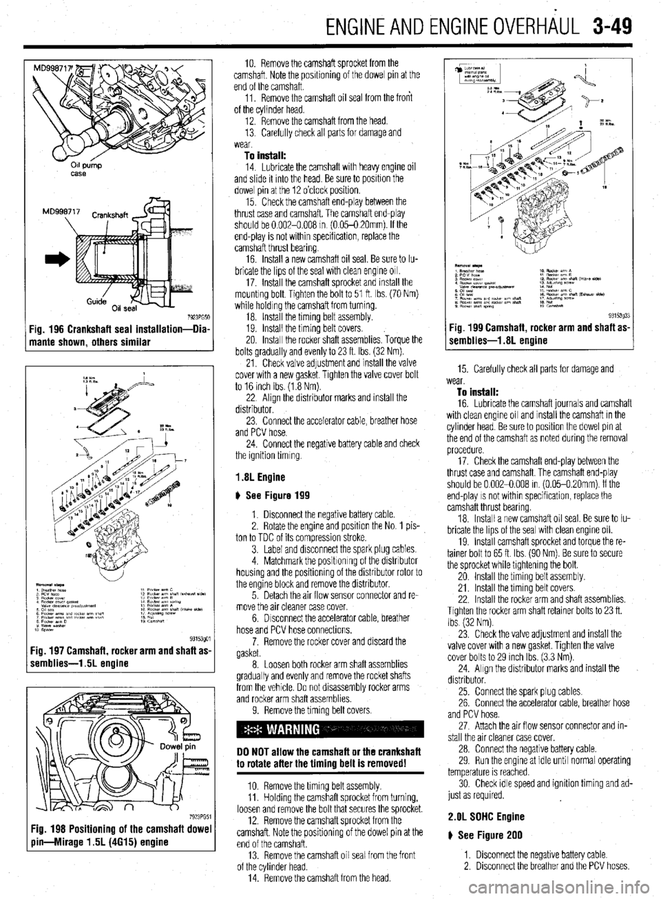
7923PG51 Fig. 196 Crankshaft seal installation-Dia
mante shown, others similar
:ig. 197 Camshaft, rocker arm and shaft as
remblies-1.5L engine
7923PG5 Fig. 198 Positioning of the camshaft dowe
pin-Mirage 1.5L (4615) engine
10. Remove the camshaft sprocket from the
camshaft. Note the positioning of the dowel pin at the
end of the camshaft.
11. Remove the camshaft oil seal from the front
of the cylinder head.
12. Remove the camshaft from the head.
13. Carefully check all parts for damage and
wear
To install:
14. Lubricate the camshaft with heavy engine oil
and slide it mto the head. Be sure to position the
dowel pin at the 12 o’clock position.
15. Check the camshaft end-play between the
thrust case and camshaft. The camshaft end-play
should be 0.002-0.008 m (0.05-O 20mm). If the
end-play is not within specification, replace the
camshaft thrust bearing.
16 Install a new camshaft oil seal. Be sure to Iu-
bricate the lips of the seal with clean engine 011.
17. Install the camshaft sprocket and install the
mountrng bolt. Tighten the bolt to 51 ft. Ibs. (70 Nm)
while holding the camshaft from turning.
18. Install the timing belt assembly.
19. Install the timing belt covers.
20. Install the rocker shaft assemblies. Torque the
bolts gradually and evenly to 23 ft. Ibs. (32 Nm).
21. Check valve adjustment and install the valve
cover with a new gasket. Tighten the valve cover bolt
to 16 inch Ibs (1.8 Nm).
22 Align the distributor marks and install the
distributor.
23. Connect the accelerator cable, breather hose
and PCV hose.
24. Connect the negative battery cable and check
the ignition timing
1.8L Engine
# See Figure 199
1. Disconnect the negative battery cable
2. Rotate the engine and position the No. 1 pis-
ton to TDC of its compression stroke.
3. Label and disconnect the spark plug cables.
4. Matchmark the positronrng of the distributor
housing and the positioning of the distributor rotor to
the engine block and remove the distributor.
5. Detach the air flow sensor connector and re-
move the air cleaner case cover.
6. Drsconnect the accelerator cable, breather
hose and PCV hose connections.
7. Remove the rocker cover and discard the
gasket.
8. Loosen both rocker arm shaft assemblies
gradually and evenly and remove the rocket shafts
from the vehicle. Do not disassembly rocker arms
and rocker arm shaft assemblies.
9. Remove the timing belt covers.
DO NOT allow the camshaft or the crankshaft
to rotate after the timing belt is removed!
10. Remove the timing belt assembly.
11. Holding the camshaft sprocket from turning,
loosen and remove the bolt that secures the sprocket.
12. Remove the camshaft sprocket from the
camshaft. Note the positioning of the dowel pin at the
end of the camshaft.
13. Remove the camshaft oil seal from the front
of the cylinder head.
14. Remove the camshaft from the head.
(r.mblies-1.8L Agine g3i53033 Fig 199 Camshaft rocker arm and shaft as-
15. Carefully check all parts for damage and
wear.
To install:
16. Lubricate the camshaft journals and camshaft
with clean engine oil and install the camshaft in the
cylinder head. Be sure to position the dowel pin at
the end of the camshaft as noted during the removal
procedure.
17. Check the camshaft end-play between the
thrust case and camshaft The camshaft end-play
should be 0.002-0.008 in. (0.05-0.20mm). If the
end-play
IS not within specification, replace the
camshaft thrust bearing
18. Install a new camshaft oil seal. Be sure to Iu-
bricate the lips of the seal with clean engine oil.
19. Install camshaft sprocket and torque the re-
tainer bolt to 65 ft. Ibs. (90 Nm). Be sure to secure
the sprocket while tightening the bolt.
20 Install the timing belt assembly.
21. Install the timing belt covers.
22. Install the rocker arm and shaft assemblies.
Tighten the rocker arm shaft retainer bolts to 23 ft.
Ibs (32 Nm).
23 Check the valve adjustment and install the
valve cover with a new gasket. Tighten the valve
cover bolts to 29 inch Ibs. (3.3 Nm).
24. Align the distributor marks and install the
distributor.
25. Connect the spark plug cables.
26. Connect the accelerator cable, breather hose
and PCV hose.
27. Attach the air flow sensor connector and in-
stall the air cleaner case cover.
28. Connect the negative battery cable.
29. Run the engine at idle until normal operating
temperature is reached.
30. Check idle speed and ignition timing and ad-
just as required.
2.OL SDHC Engine
# See Figure 200
1. Disconnect the negative battery cable.
2. Disconnect the breather and the PCV hoses
Page 111 of 408
.
3-50 ENGINEANDENGINEOVERHALJL
F
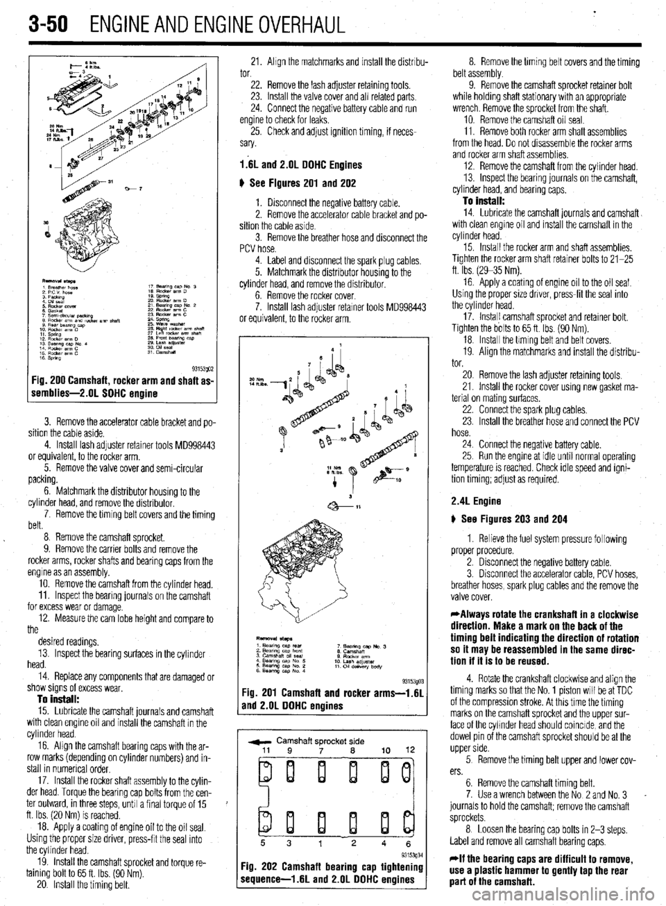
1 s 93153QO2 :ig. 200 Camshaft, rocker arm and shaft as-
iemblies-2.01 SOHC ermine
3. Remove the accelerator cable bracket and po-
sition the cable aside.
4. Install lash adjuster retainer tools MD998443
or equivalent, to the rocker arm.
5. Remove the valve cover and semi-circular
packing.
6. Matchmark the distributor housing to the
cylinder head, and remove the distributor,
7. Remove the timing belt covers and the timing
belt.
8 Remove the camshaft sprocket.
9. Remove the carrier bolts and remove the
rocker arms, rocker shafts and bearing caps from the
engine as an assembly.
10. Remove the camshaft from the cylinder head.
11. Inspect the bearing journals on the camshaft
for excess wear or damage.
12. Measure the cam lobe height and compare to
the
desired readings.
13. Inspect the bearing surfaces in the cylinder
head.
14. Replace any components that are damaged or
show signs of excess wear,
To install:
15. Lubricate the camshaft journals and camshaft
with clean engine oil and install the camshaft in the
cylinder head.
16. Align the camshaft bearing caps with the ar-
row marks (depending on cylinder numbers) and in-
stall in numerical order,
17. Install the rocker shaft assembly to the cylin-
der head. Torque the bearing cap bolts from the cen-
ter outward, in three steps, unh a final torque of 15
ft. Ibs. (20 Nm) is reached.
18. Apply a coating of engine oil to the oil seal.
Using the proper size driver, press-frt the seal into
the cylinder head.
19. install the camshaft sprocket and torque re-
taining bolt to 65 ft. Ibs. (90 Nm).
20. Install the timing belt. 21. Ahgn the matchmarks and install the distrrbu- 8. Remove the timing belt covers and the timing
tor. belt assembly.
22. Remove the lash adjuster retaining tools.
23. Install the valve cover and all related parts
24. Connect the negative battery cable and run
engine to check for leaks,
25. Check and adjust ignition timing, if neces-
sary.
l.‘6L and 2.lJL DOHC Engines
6 See Figures 201 and 202
1. Disconnect the negative battery cable.
2. Remove the accelerator cable bracket and po-
sition the cable aside.
3. Remove the breather hose and disconnect the
PCV hose. 9. Remove the camshaft sprocket retainer bolt
while holding shaft stationary with an appropriate
wrench. Remove the sprocket from the shaft.
10. Remove the camshaft oil seal.
11. Remove both rocker arm shaft assemblies
from the head. Do not drsassemble the rocker arms
and rocker arm shaft assemblies.
12. Remove the camshaft from the cylinder head.
13. inspect the bearing journals on the camshaft,
cylinder head, and bearing caps.
To install:
14. Lubricate the camshaft journals and camshaft
with clean engine oil and install the camshaft in the
cylinder head.
4. Label and disconnect the spark plug cables.
5. Matchmark the distributor housing to the
cylinder head, and remove the distributor.
6. Remove the rocker cover.
7. Install lash adjuster retarner tools MD998443
or equivalent, to the rocker arm. 15. Install the rocker arm and shaft assemblies.
Tighten the rocker arm shaft retainer bolts to 21-25
ft. Ibs. (2935 Nm).
16 Apply a coating of engine oil to the oil seal.
Using the proper size driver, press-fit the seal into
the cylinder head.
17. Instal! camshaft sprocket and retainer bolt.
Tighten the bolts to 65 ft. Ibs. (90 Nm).
18. Install the hming belt and belt covers.
19. Align the matchmarks and install the distribu-
tor.
93153gO: :ig. 201 Camshaft and rocker arms-i.61
rnd 2.OL DOHC engines
r ,
w Camshaft sprocket side
ei i i ij
20. Remove the lash adjuster retaining tools,
21. Install the rocker cover using new gasket ma-
terial on mating surfaces,
22. Connect the spark plug cables.
23. Install the breather hose and connect the PCV
hose.
24. Connect the negative battery cable.
25. Run the engme at idle until normal operating
temperature is reached. Check idle speed and igni-
tion timing; adjust as required.
2.4L Engine
) See Figures 203 and 204
1. Relieve the fuel system pressure following
proper procedure.
2. Disconnect the negative battery cable.
3. Disconnect the accelerator cable, PCV hoses,
breather hoses, spark plug cables and the remove the
valve cover.
*Always rotate the crankshaft in a clockwise
direction. Make a mark on the back of the
timing belt indicating the direction of rotation
so it may be reassembled in the same direc-
tion if it is to be reused.
4. Rotate the crankshaft clockwise and align the
timing marks so that the No. 1 piston will be at TDC
of the compression stroke. At this time the timing
marks on the camshaft sprocket and the upper sur-
face of the cyhnder head should coincide, and the
dowel pin of the camshaft sprocket should be at the
upper side.
5 Remove the timing belt upper and lower cov-
ers.
6. Remove the camshaft timing belt.
7. Use a wrench between the No 2 and No. 3
journals to hold the camshaft; remove the camshaft
sprockets.
8 Loosen the bearing cap bolts in 2-3 steps.
Label and remove all camshaft bearing caps,
*If the bearing caps are difficult to remove,
use a plastic hammer to gently tap the rear
part of the camshaft.
Page 118 of 408
ENGINEANDENGINEOVERHAUL 3-57
Anything that generates heat and/or friction WIII
eventually burn or wear out (for example, a light bulb
generates heat, therefore its life span is limited). With
this in mind, a running engine generates tremendous
amounts of both; friction is encountered by the mov-
ing and rotating parts inside the engine and heat is
created by friction and combustion of the fuel How-
ever, the engine has systems designed to help reduce
the effects of heat and friction and provide added
longevrty. The oiling system reduces the amount of
friction encountered by the moving parts inside the
engine, while the cooling system reduces heat cre-
ated by friction and combustion If either system is
not maintained, a break-down will be inevitable.
Therefore, you can see how regular maintenance can
affect the service life of your vehicle, If you do not
drain, flush and refill your cooling system at the
proper intervals, deposits WIII begin to accumulate in
the radiator, thereby reducing the amount of heat it
can extract from the coolant The same applies to
your oil and filter; If it is not changed often enough it
becomes laden with contaminates and is unable to
properly lubricate the engine. This increases friction
and wear.
There are a number of methods for evaluating the
condition of your engine. A compression test can re-
veal the condition of your pistons, piston rings,
cylinder bores, head gasket(s), valves and valve
seats. An oil pressure test can warn you of possible
engine bearing, or oil pump failures. Excessrve oil
consumption, evidence of oil in the engine air intake
area and/or bluish smoke from the tailpipe may indi-
cate worn piston rings, worn valve guides and/or
valve seals. As a general rule, an engine that uses no
more than one quart of oil every 1000 miles is in
good condition. Engines that use one quart of oil or
more in less than 1000 miles should first be checked
for oil leaks. If any oil leaks are present, have them
fixed before determining how much oil is consumed
by the engine, especrally if blue smoke is not visible
at the tailpipe
COMPRESSION TEST
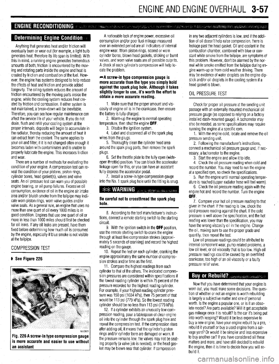
# See Figure 226
tccs3801 Fig. 226 A screw-in type compression gauge
is more accurate and easier to use without
an assistant
A noticeable lack of engine power, excessive oil
consumption and/or poor fuel mileage measured
over an extended period are all indicators of internal
engine wear. Worn piston rings, scored or worn
cylinder bores, blown head gaskets, sticking or burnt
valves, and worn valve seats are all possible culprits.
A check of each cylinders compression WIII help lo-
cate the problem.
*A screw-in type compression gauge is
more accurate than the type you simply hold
against the spark plug hole. Although it takes
slightly longer to use, it’s worth the effort to
obtain a more accurate reading.
1 Make sure that the proper amount and vis-
cosity of engine oil is in the crankcase, then ensure
the battery is fully charged.
2. Warm-up the engine to normal operating
temperature, then shut the engine
OFF. 3. Disable the ignition system.
4. Label and disconnect all of the spark plug
wires from the plugs,
5. Thoroughly clean the cylinder head area
around the spark plug ports, then remove the spark
plugs.
6. Set the throttle plate to the fully open (wide-
open throttle) position You can block the accelerator
linkage open for this, or you can have an assistant
fully depress the accelerator pedal.
7. Install a screw-in type compression gauge
into the No. 1 spark plug hole until the fitting is snug.
Be careful not to crossthread the spark plug
hole.
8. According to the tool manufacturers instruc-
tions, connect a remote starting switch to the starting
circuit.
9. With the ignition switch in the
OFF position,
use the remote starting switch to crank the engine
through at least five compression strokes (approxi-
mately 5 seconds of cranking) and record the highest
reading on the gauge
10. Repeat the test on each cylinder, cranking the
engine approximately the same number of compres-
sion strokes and/or time as the first.
11. Compare the hrghest readings from each
cylinder to that of the others. The indicated compres-
sion pressures are considered within specifications if
the lowest reading cylinder is within 75 percent of the
pressure recorded for the highest reading cylinder
For example, if your highest reading cylinder pres-
sure was 150 psi (1034 kPa), then 75 percent of that
would be 113 psi (779 kPa). So the lowest reading
cylinder should be no less than 113 psi (779 kPa).
12. If a cylinder exhibits an unusually low com-
pression reading, pour a tablespoon of clean engine
oil into the cylinder through the spark plug hole and
repeat the compression test. If the compression rises
after adding oil, it means that the cylinder’s piston
rings and/or cylinder bore are damaged or worn, If
the pressure remains low, the valves may not be seat-
ing properly (a valve job is needed), or the head gas-
ket may be blown near that cylinder. If compression in any two adjacent cylinders is low, and if the addi-
tion of oil doesn’t help raise compression, there is
leakage past the head gasket. Oil and coolant in the
combustion chamber, combined with blue or con-
stant white smoke from the tailpipe, are symptoms of
this problem. However, don’t be alarmed by the nor-
mal white smoke emitted from the tailpipe during en-
gine warm-up or from cold weather driving. There
may be evidence of water droplets on the engine dip-
stick and/or oil droplets in the cooling system if a
head gasket is blown.
OIL PRESSURETEST
Check for proper oil pressure at the sending unit
passage with an externally mounted mechanical oil
pressure gauge (as opposed to relying on a factory
Installed dash-mounted gauge). A tachometer may
also be needed, as some specifications may require
running the engine at a specific rpm.
1. With the engine cold, locate and remove the oil
pressure sending unit.
2. Followrng the manufacturers instructions,
connect a mechanical oil pressure gauge and, if nec-
essary, a tachometer to the engine.
3 Start the engine and allow it to idle.
4 Check the oil pressure reading when cold and
record the number. You may need to run the engine
at a specified rpm, so check the specifications,
5. Run the engine until normal operating temper-
ature is reached (upper radiator hose will feel warm)
6. Check the oil pressure reading again with the
engine hot and record the number. Turn the engine
OFF. 7. Compare your hot oil pressure reading to that
given in the chart If the reading is low, check the
cold pressure reading against the chart. If the cold
pressure IS well above the specification, and the hot
reading was lower than the specification, you may
have the wrong viscosity oil in the engine. Change
the oil, making sure to use the proper grade and
quantity, then repeat the test.
Low oil pressure readings could be attributed to
internal component wear, pump related problems, a
low oil level, or oil viscosity that is too low. High oil
pressure readings could be caused by an overfilled
crankcase, too htgh of an oil viscosity or a faulty
pressure relief valve.
Now that you have determined that your engine is
worn out, you must make some decisions. The ques-
tion of whether or not an engine IS worth rebuilding
is largely a subjective matter and one of personal
worth. Is the engine a popular one, or IS it an obso-
lete model? Are parts available? Will it get acceptable
gas mileage once It is rebuilt? Is the car its being put
into worth keeping? Would it be less expensive to
buy a new engine, have your engine rebuilt by a pro,
rebuild it yourself or buy a used engine from a sal-
vage yard? Or would It be simpler and less expensive
to buy another car? If you have considered all these
matters and more, and have still decided to rebuild
the engine, then it is time to decide how you will re-
build it.