1900 MITSUBISHI DIAMANTE ignition
[x] Cancel search: ignitionPage 64 of 408
ENGINEANDENGINEOVERHAUL 3-3
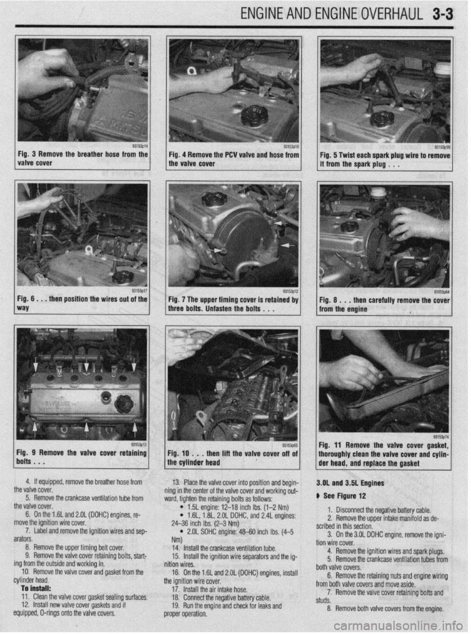
Fig. 3 Remove the
breather hose from the Fig. 4 Remove the PCW valve
and hose from
93153p17 Fig. 6 . . . then position the wires out of the
Fig. 7 The upper timing cover is retained by
three bolts. Unfasten the bolts . . . Fig. 8 . . . then carefully remove the cover
from the engine
Fig. 9 Remove the valve cover retaini
then lift the valve cover
4. If equipped, remove the breather hose from
13.
the valve cover. Place the valve cover into position and begin-
5. Remove the crankcase ventilation tube from ning in the center of the valve cover and working out-
the valve cover. ward, tighten the retaining bolts as follows:
6. On the 1.6L and 2.gL (DOHC) engines, re-
l 15L engine: 12-18 inch Ibs. (l-2 Nm)
move the ignition wire cover. l 1.6L, 1.8L, 2.OL DOHC, and 2.4L engines:
7. Label and remove the ignition wires and sep- 24-36 inch Ibs. (2-3 Nm)
arators. * 2.OL SOHC engine: WO inch Ibs. (4-5
8. Remove the upper timing belt cover. Nm)
14. Install the crankcase ventilation tube.
9. Remove the valve cover retaining bolts, start
15.
ing from the outside and working in. Install the ignition wire separators and the ig-
nition wires.
10. Remove the valve cover and gasket from the
16.
cylinder head. On the 1.6L and 2.OL (DOHC) engines, install
the ignition wire cover.
To install:
17. Install the air intake hose.
11. Clean the valve cover gasket sealing surfaces,
12, Install new valve cover gaskets and if 18. Connect the negative battery cable.
equipped, O-rings onto the valve covers. 19. Run the engine and check for leaks and
proper operation. 3.OL and 3.5L Engines
b See Figure 12
1. Disconnect the negative battery cable.
2. Remove the upper intake manifold as de-
scribed in this section.
3. On the 3.OL DOHC engine, remove the igni-
tion wire cover.
4. Remove the ignition wires and spark plugs.
5. Remove the crankcase ventilation tubes from
both valve covers.
6. Remove the retaining nuts and engine wiring
from both valve covers and move aside.
7. Remove the valve cover retaining bolts and
studs.
8. Remove both valve covers from the engine.
Page 65 of 408
![MITSUBISHI DIAMANTE 1900 Repair Manual 3-4 ENGINEANDENGINEOVERHAUL
Rear bank
6 011 010 og
1.03 07 02]
7923PG25 Fig. 12 Rocker cover bolt torque se-
quence-3.01 DOHC engine
To install:
9. Clean the valve cover gasket sealing SW
face](/manual-img/19/57096/w960_57096-64.png "MITSUBISHI DIAMANTE 1900 Repair Manual 3-4 ENGINEANDENGINEOVERHAUL
Rear bank
6 011 010 og
1.03 07 02]
7923PG25 Fig. 12 Rocker cover bolt torque se-
quence-3.01 DOHC engine
To install:
9. Clean the valve cover gasket sealing SW
face")
3-4 ENGINEANDENGINEOVERHAUL
Rear bank
6 011 010 og
1.03 07 02]
7923PG25 Fig. 12 Rocker cover bolt torque se-
quence-3.01 DOHC engine
To install:
9. Clean the valve cover gasket sealing SW
faces.
10 Install new valve cover gaskets onto the valve
covers.
11. Place the valve covers into position.
12. Reinstall the valve cover retaining bolts and
studs and tighten in sequence to:
l 3.OL SOHC engine: 7 ft. Ibs. (9 Nm) l 3.OL DOHC engine: 42-54 inch Ibs. (4-5
NM
l 3.5L engine: 30 inch Ibs. (3 Nm)
13. Install the engine wiring and tighten the re-
taining nuts.
14. Install the crankcase ventilation tubes into
both valve covers.
15. Install the ignition wire separators, the igni-
tion wires, and the spark plugs.
16. On the 3.OL DOHC engine, install the ignition
wire cover.
17. Install the upper intake manifold as described
in this section.
18. Connect the negative battery cable.
19. Run the engine and check for leaks and
proper operation.
( ser;lblies-l.5L dngine g3’53goi Fig 13 Camshaft rocker arm and shafl as- REMOVAL &INSTALLATION
1.5L and 1.8L Eflgin8S
,# See Figures 13 and 14
1. Disconnect the negative battery cable.
2. For 1.8L engines, label and disconnect the
spark plug cables.
3. Disconnect the accelerator cable, breather
hose and PCV hose connections.
4. Remove the rocker cover.
5. Loosen both rocker arm shaft assemblies
gradually and evenly and remove the rocket shafts
from the vehicle.
To install: 7. Lubricate the rocker shaft with clean engine
oil and Install the rockers and springs.
8. Install the rocker arm and shaft assemblies.
Tighten the rocker arm shaft retainer bolts to 23 ft.
Ibs. (32 Nm).
9. Check valve adjustment and install the valve
cover. Tighten the valve cover bolts to 16 inch Ibs.
(1.8 Nm) for the 1.5L engine or to 29 inch Ibs. (3.3
Nm) for the 1.8L engine.
10. If detached, connect the spark plug cables.
11. Connect the accelerator cable, breather hose
and PCV hose.
12. Connect the negative battery cable.
2.OL SOHC Engine
# See Figure 15
6. If disassembly is required, keep all parts in
the exact order of removal. On this engine, the hydraulic lifters are built into
the rocker arms. If lifter service is required, simply
1. Breather hose
2. P.C.V. hose
3. Rocker cover
4. Rocker cover gasket
Valve clearance pre-adjustment
5. Oil seal
6. Oil seal
7. Rocker arms and rocker arm shaft
6. Rocker arms and rocker arm shaft
9. Rocker shaft spring 10. Rocker arm A
11. Rocker arm 6
12. Rocker arm shaft (Intake side)
13. Adjusting screw
14. Nut
15. Rocker arm C
16. Rocker arm shaft (Exhaust side)
17. Adjusting screw
18. Nut
19. Camshaft
7923PG27 :ig. 14 Camshaft, rocker arm and shaft assemblies-l .8L engine
Page 66 of 408
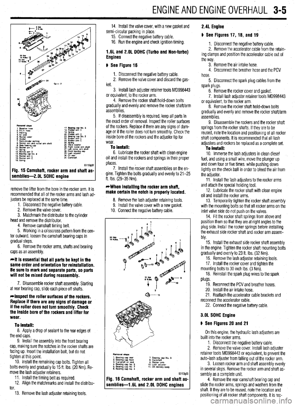
ENGINEANDENGINEOVERHALJL 3-5
Fig. 15 Camshaft, rocker arm and shaft as-
remblies-2.01 SOHC engine
remove the lifter from the bore in the rocker arm. It is
recommended that all of the rocker arms and lash ad-
justers be replaced at the same time.
1. Disconnect the negative battery cable.
2. Remove the valve cover.
3. Matchmark the distributor to the cylinder
head and remove the distributor.
4. Remove camshaft timing belt.
5. Working in a crisscross pattern from the cen-
ter outward, loosen the camshaft bearing caps in
gradual steps.
6. Remove the rocker arms, shafts and bearing
caps as an assembly.
*It is essential that all parts be kept in the
same order and orientation for reinstallation.
Be sure to mark and separate parts, so parts
will not be mixed during reassembly.
7. Disassemble rocker shaft assembly. Starting
at rear bearing cap, slide each piece off shafts.
*Inspect the roller surfaces of the rockers.
Replace if there are any signs of damage or
if the roller does not turn smoothly. Check
the inside bore of the rockers and lifter for
wear.
To install:
8. Apply a drop of sealant to the rear edges of
the end caps.
9. Install the assembly into the front bearing
cap, making sure the notches in the rocker shafts are
facing up. Insert the installation bolt, but do not
tighten at this point.
10. Install the remaining cap bolts. Tighten all
bolts evenly and gradually to 15 ft. Ibs. (20 Nm). Re-
move the lash adjuster retainers.
11. Install the timing belt as required.
12. Align the matchmarks and install the distribu-
tor.
13. Remove the lash adjuster retaining tools. 14. Install the valve cover, with a new gasket and
semi-circular packing in place.
15. Connect the negative battery cable.
16. Run the engine and check ignition timing.
1.6L and 2.OL DOHC (Turbo and Non-turbo)
Engines
6 See Figure 16
1. Disconnect the negative battery cable.
2. Remove the valve cover and discard the gas-
ket.
3. Install lash adjuster retainer tools MD998443
or equivalent, to the rocker arm.
4. Remove the rocker shaft hold-down bolts
gradually and evenly and remove the rocker shaft/arm
assemblies.
5. If disassembly is required, keep all parts in
the exact order of removal. Inspect the roller surfaces
of the rockers. Replace if there are any signs of dam-
age or if the roller does not turn smoothly. Check the
inside bore of the rockers and the adjuster tip for
wear.
To install: 6. Lubricate the rocker shaft with clean engine
oil and install the rockers and springs in their proper
places.
7. Install the rocker shaft assemblies on the en-
gine. Tighten the bolts gradually and evenly to 21-25
ft. Ibs. (29-35 Nm).
*When installing the rocker arm shaft,
make certain the notch is properly located.
8. Remove the lash adiuster retainina tools
9. Install the valve cover with a new gasket.
10. Connect the negative battery cable.
F :ig. 16 Camshaft, rocker arm and shaft as
s iemblies-1.6L and 2.OL DOHC engines
*o Nm
IILlbs -
9315390 3
2.4L Engine
# See Figures 17, 16, and 19
1. Disconnect the negative battery cable.
2. Remove the accelerator cable from the retain-
ing clamps and position the accelerator cable out of
the way.
3. Remove the air intake hose.
4. Disconnect the breather hose and the PCV
hose.
5. Disconnect the spark plug cables from the
spark plugs.
6. Remove the rocker cover and gasket.
7. Install lash adjuster retainer tools MD998443
or equivalent, to the rocker arm.
8. Remove the rocker shaft hold-down bolts
gradually and evenly and remove the rocker shaft/arm
assemblies.
9. Disassemble the rockers and the rocker shaft
springs from the rocker shafts. If they are to be
reused, note the location and positionrng of all rocker
shaft components. It is recommended that all lash
adjusters and rockers be replaced as a complete set.
To install: 10. Immerse the lash adjusters in clean diesel
fuel, and using a small wire, move the plunger up
and down four or five times. while pushing down
lightly on the check ball in order to bleed the air from
the adjuster.
11. Install the lash adjusters to the rocker arms
and attach the special holding tool.
12. Lubricate the rocker shaft with clean engine
oil and install the rocker arms.
13. Temporarily tighten the rocker shaft assembly
with the mounting bolts so that all rocker arms on the
inlet valve side do not push on the valves,
14. Fit the rocker shaft springs from above and
position them so that they are at right angles to the
plug side. Install the rocker springs before installing
the exhaust side rocker shaft and rocker arm assem-
bly.
15. Install the exhaust side rocker shaft assembly
in the engine. Tighten the rocker shaft mounting bolts
gradually and evenly to 23 ft. Ibs. (32 Nm).
16. Remove the lash adjuster retaining tools.
17. Install the rocker cover and tighten the
mounting bolts to 30 inch Ibs. (3 Nm).
18. Reinstall the spark plug wires to the spark
plugs.
19. Reconnect the PCV and breather hoses.
20. Install the air intake hose.
21. Reattach the accelerator cable brackets and
reconnect the accelerator cable.
22. Connect the negative battery cable.
3.OL SOHC Engine
6 See Figures 20 and 21
On this engine, the hydraulic lash adjusters are
built into the rocker arms,
1. Disconnect the negative battery cable.
2. Remove the valve cover. Install lash adjuster
retainer tools MD998443 or equivalent, to prevent the
auto-lash adjuster from falling out of the rocker arm.
3. Loosen rocker arm and shaft assembly evenly
in several steps. Remove the rocker arm and shaft as-
sembly as a complete unit.
4. Remove the rear camshaft bearing cap and
slide the rocker arms, springs and washers from the
shaft. If they are to be reused, note the location and
positioning of all rocker shaft components. It is rec-
Page 70 of 408
ENGINEANDENGINEOVERHAUL 3-9
28. Fill the system with coolant.
29. Connect the negative battery cable, run the
vehicle until the thermostat opens, fill the radiator
completely.
30. Check and adjust the idle speed and ignition
timing.
31. Once the vehicle has cooled, recheck the
coolant level.
1.8L Engine
) See Figures 29 and 30
I. Relieve the fuel system pressure.
Observe all applicable safety precautions
when working around fuel. Whenever servic-
ing the fuel system, always work in a well
ventilated area. Do not allow fuel spray or
vapors to come in contact with a spark or
open flame. Keep a dry chemical fire extin-
guisher near the work area. Always keep fuel
in a container specifically designed for fuel
storage; also, always properly seal fuel con-
tainers to avoid the possibility of fire or ex-
plosion.
2. Disconnect battery negative cable and drain
the cooling system.
Never open, service or drain the radiator or
cooling system when hot; serious burns can
occur from the steam and hot coolant. Also,
when draining engine coolant, keep in mind
that cats and dogs are attracted to ethylene
glycol antifreeze and could drink any that is
leff in an uncovered container or in puddles
on the ground. This will prove fatal in suffi-
cient quantities. Always drain coolant into a
sealable container. Coolant should be reused
unless it is contaminated or is several years
old.
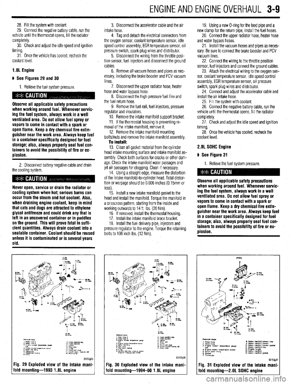
Fig. 29 Exploded view of the intake mani.
old mounting-1993 1.8L engine
3. Disconnect the accelerator cable and the air
intake hose.
4. Tag and detach the electrical connectors from
the oxygen sensor, coolant temperature sensor, idle
speed control assembly, EGR temperature sensor, oil
pressure switch, spark plug wires and distributor.
5. Disconnect the wiring from the throttle posi-
tion sensor, fuel Injectors and disconnect the ground
cables.
6. Remove all vacuum hoses and pipes as nec-
essary, including the brake booster and PCV vacuum
lines.
7. Disconnect the upper radiator hose, heater
hose and water bypass hose.
8. Disconnect the high pressure fuel line and
the fuel return hose.
9. Remove the fuel rail, fuel injectors, pressure
regulator and insulators.
10. Remove the intake manifold support bracket.
11. If the thermostat housing is preventing re-
moval of the Intake manifold, remove it.
12. Remove the intake manifold mounting
bolts/nuts and remove the intake manifold assembly.
To install: 13. Clean all gasket material from the cylinder
head intake mounting surface and intake manifold as-
sembly Check both surfaces for cracks or other dam-
age. Check the intake manifold water passages and
jet air passages for clogging. Clean if necessary.
14. Using a straight edge, measure the distortion
of the intake manifold-to-cylinder head. Total distor-
tion or warpage should be 0.006 inches (0.15mm or
less).
15. Install a new intake manifold gasket to the
head and install the manifold. Torque the manifold in
a crrsscross pattern, starting from the inside and
working outwards to 14 ft. Ibs. (20 Nm).
16. If removed, install the thermostat housing.
17. Install the Intake manifold brace bracket.
18. Install the fuel delivery pipe, injectors and
pressure regulator to the engine. Torque the retaining
bolts to 108 Inch Ibs. (12 Nm). 19. Using a new O-ring for the feed pipe and a
new clamp for the return pipe, install the fuel hoses,
20. Connect the upper radiator hose, heater hose
and water bypass hoses.
21. Install the vacuum hoses and pipes as neces-
sary. Be sure to connect the brake booster and PCV
vacuum lines
22. Connect the wiring to the throttle position
sensor, fuel injectors and connect the ground cables,
23. Attach the electrical wiring to the oxygen sen-
sor, coolant temperature sensor, Idle speed control
assembly, EGR temperature sensor, oil pressure
switch, spark plug wires and distributor.
24. Connect and adjust the accelerator cable and
install the air intake hose.
25. Fill the system with coolant.
26. Connect the negative battery cable, run the
vehicle until the thermostat opens, fill the radiator
completely.
27. Check and adjust the idle speed and ignition
timing.
28. Once the vehicle has cooled, recheck the
coolant level. 2.OL SOHC Engine
# See Figure 31
1. Relieve the fuel system pressure.
Observe all applicable safety precautions
when working around fuel. Whenever servic-
ing the fuel system, always work in a well
ventilated area. Do not allow fuel spray or
vapors to come in contact with a spark or
open flame. Keep a dry chemical fire extin-
guisher near the work area. Always keep fuel
in a container specifically designed for fuel
storage; also, always properly seal fuel con-
tainers to avoid the possibility of fire or ex-
plosion.
Fig. 30 Exploded view of the intake mani,
iold mounting-1994-00 1.8L engine Fig. 31 Exploded view of the intake mani
fold mounting-2.01 SOHC ermine
Page 71 of 408
3-10 ENGINEANDENGINEOVERHAUL
2. Disconnect the battery negative cable.
3. Drain the cooling system.
Never open, service or drain the radiator or
cooling system when hot; serious burns can
occur from the steam and hot coolant. Also,
when draining engine coolant, keep in mind
that cats and dogs are attracted to ethylene
glycol antifreeze and could drink any that is
left in an uncovered container or in puddles
on the ground. This will prove fatal in suffi-
cient quantities. Always drain coolant into a
sealable container. Coolant should be reused
unless it is contaminated or is several years
old.
4 Disconnect the accelerator cable and air in-
take hose.
5. Disconnect the upper radiator hose, heater
hose and water bypass hose.
6. Unplug the vacuum connection at the power
brake booster and the PCV valve if still connected.
Disconnect all remaining vacuum hoses and pipes as
necessary.
7. Disconnect the high pressure fuel line, fuel
return hose and remove throttle control cable brack-
ets
8. Tag and detach the electrical connectors from
the oxygen sensor, coolant temperature sensor,
therm0 switch, idle speed control assembly, EGR
temperature sensor, distributor, fuel injectors and
spark plug wires. Position the engine wiring harness
aside.
9. Matchmark the distributor housing to the in-
take manifold, and remove the distributor.
10. Remove the intake manifold bracket and the
engine hanger.
11. If the thermostat housing is preventing re-
moval of the intake manifold, remove it.
12. Remove the intake manifold mounting bolts
and remove the intake manifold assembly. Drsassem-
ble manifold from the Intake plenum on a work bench
as required
To install: 13. Clean all gasket material from the cylinder
head intake mounting surface and intake manifold as-
sembly. Check both surfaces for cracks or other dam-
age. Check the intake manifold water passages and
jet air passages for clogging. Clean if necessary.
14 Assemble the intake manifold assembly using
all new gaskets. Torque air intake plenum bolts to
11-14ff. Ibs. (15-19 Nm).
15. Install a new intake manifold gasket to the
head and install the manifold. Torque the manifold in
a crrsscross pattern, starting from the inside and
working outwards to 11-14 ff. Ibs. (15-19 Nm).
16. Install the fuel delivery pipe, injectors and
pressure regulator to the engine. Torque the retaining
bolts to 4 ft. Ibs (6 Nm).
17. install the thermostat housing, intake mani-
fold brace bracket, and engine hanger bracket.
18 Connect or install all hoses, cables and elec-
trical connectors that were removed or disconnected
during the removal procedure.
19. Align the distributor matchmarks and install
the distributor.
20. Fill the system with coolant,
21. Connect the negative battery cable, run the
vehicle until the thermostat opens, fill the radiator
completely. 22. Adjust the accelerator cable. Check and ad-
just the idle speed and ignition timing.
23. Once the vehicle has cooled, recheck the
coolant level.
1.6L and 2.OL DDHC Engines
# See Figure 32
1. Relieve the fuel system pressure.
Observe all applicable safety precautions
when working around fuel. Whenever servic-
ing the fuel system, always work in a well
ventilated area. Do not allow fuel spray or
vapors to come in contact with a spark or
open flame. Keep a dry chemical fire extin-
guisher near the work area. Always keep fuel
in a container specifically designed for fuel
storage; also, always properly seal fuel con-
tainers to avoid the possibility of fire or ex-
ulosion.
2. Disconnect battery negative cable and drain
the cooling system.
Never open, service or drain the radiator or
cooling system when hot; serious burns can
occur from the steam and hot coolant. Also,
when draining engine coolant, keep in mind
that cats and dogs are attracted to ethylene
glycol antifreeze and could drink any that is
left in an uncovered container or in puddles
on the ground. This will prove fatal in suffi-
cient quantities. Always drain coolant into a
sealable container. Coolant should be reused
unless it is contaminated or is several years
old.
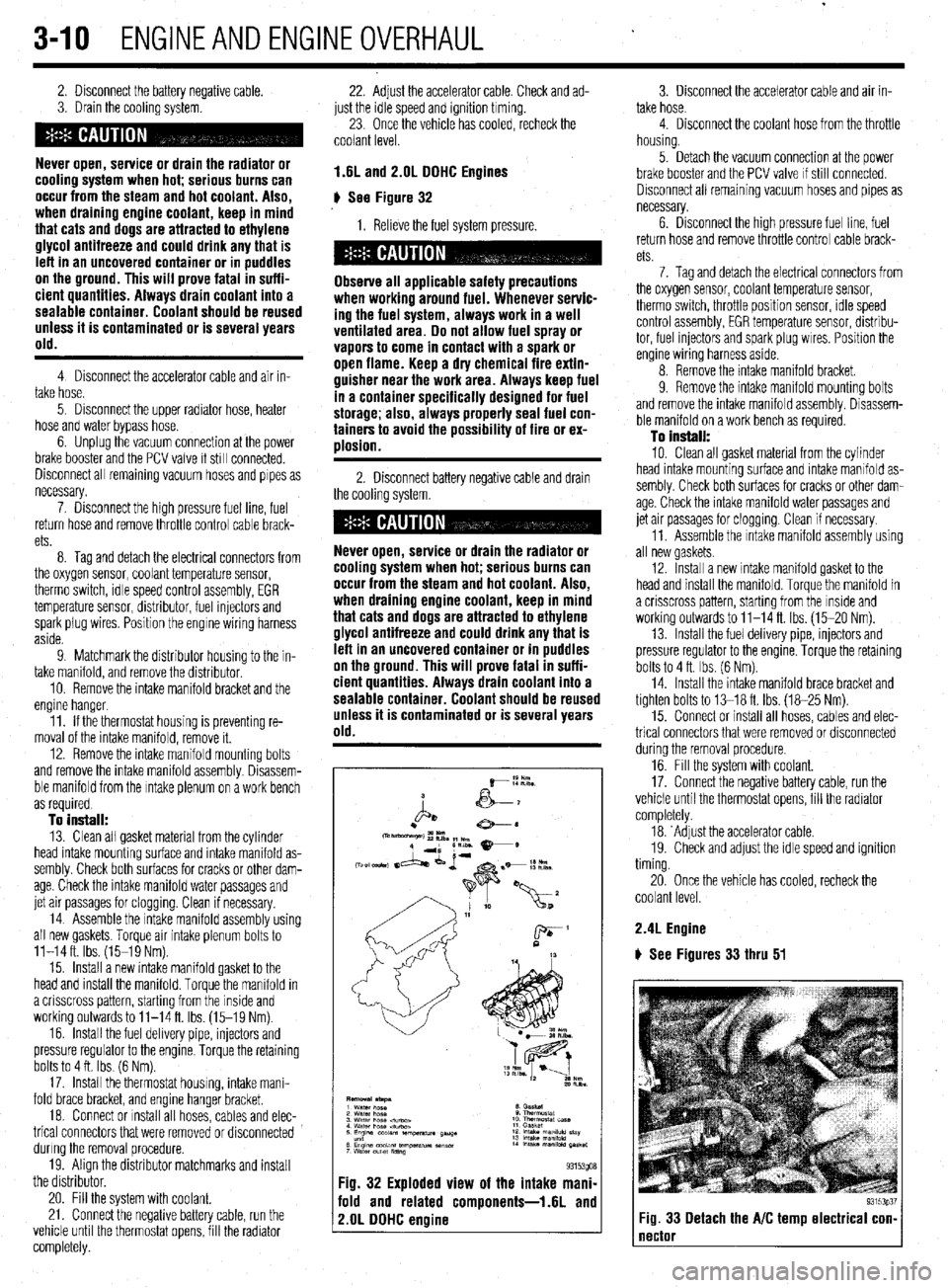
Fig. 32 Exploded view of the intake mani-
fold and related components-1.6L and
2.OL DDHC engine
3. Disconnect the accelerator cable and air in-
take hose.
4. Disconnect the coolant hose from the throttle
housing.
5. Detach the vacuum connection at the power
brake booster and the PCV valve If still connected.
Disconnect all remaining vacuum hoses and pipes as
necessary.
6. Drsconnect the high pressure fuel line, fuel
return hose and remove throttle control cable brack-
ets
7. Tag and detach the electrical connectors from
the oxygen sensor, coolant temperature sensor,
therm0 switch, throttle position sensor, rdle speed
control assembly, EGR temperature sensor, distribu-
tor, fuel injectors and spark plug wires. Position the
engine wiring harness aside.
8. Remove the intake manifold bracket.
9. Remove the intake mamfold mounting bolts
and remove the intake manifold assembly. Disassem-
ble manifold on a work bench as required.
To install:
10. Clean all gasket material from the cylinder
head intake mounting surface and intake manifold as-
sembly. Check both surfaces for cracks or other dam-
age. Check the intake manifold water passages and
jet air passages for clogging. Clean if necessary.
11. Assemble the Intake manifold assembly using
all new gaskets.
12. Install a new intake manifold gasket to the
head and install the manifold. Torque the manifold in
a crisscross pattern, starting from the inside and
working outwards to 11-14 ft. Ibs. (15-20 Nm).
13. Install the fuel delivery pipe, injectors and
pressure regulator to the engine. Torque the retaining
bolts to 4 ft. Ibs. (6 Nm).
14. Install the intake manifold brace bracket and
tighten bolts to 13-18 ft. Ibs. (18-25 Nm).
15. Connect or install all hoses, cables and elec-
trical connectors that were removed or disconnected
during the removal procedure.
16. Fill the system with coolant.
17. Connect the negative battery cable, run the
vehicle until the thermostat opens, fill the radiator
completely.
18. ‘Adjust the accelerator cable.
19. Check and adjust the idle speed and ignition
timing.
20. Once the vehicle has cooled, recheck the
coolant level.
2.4L Engine
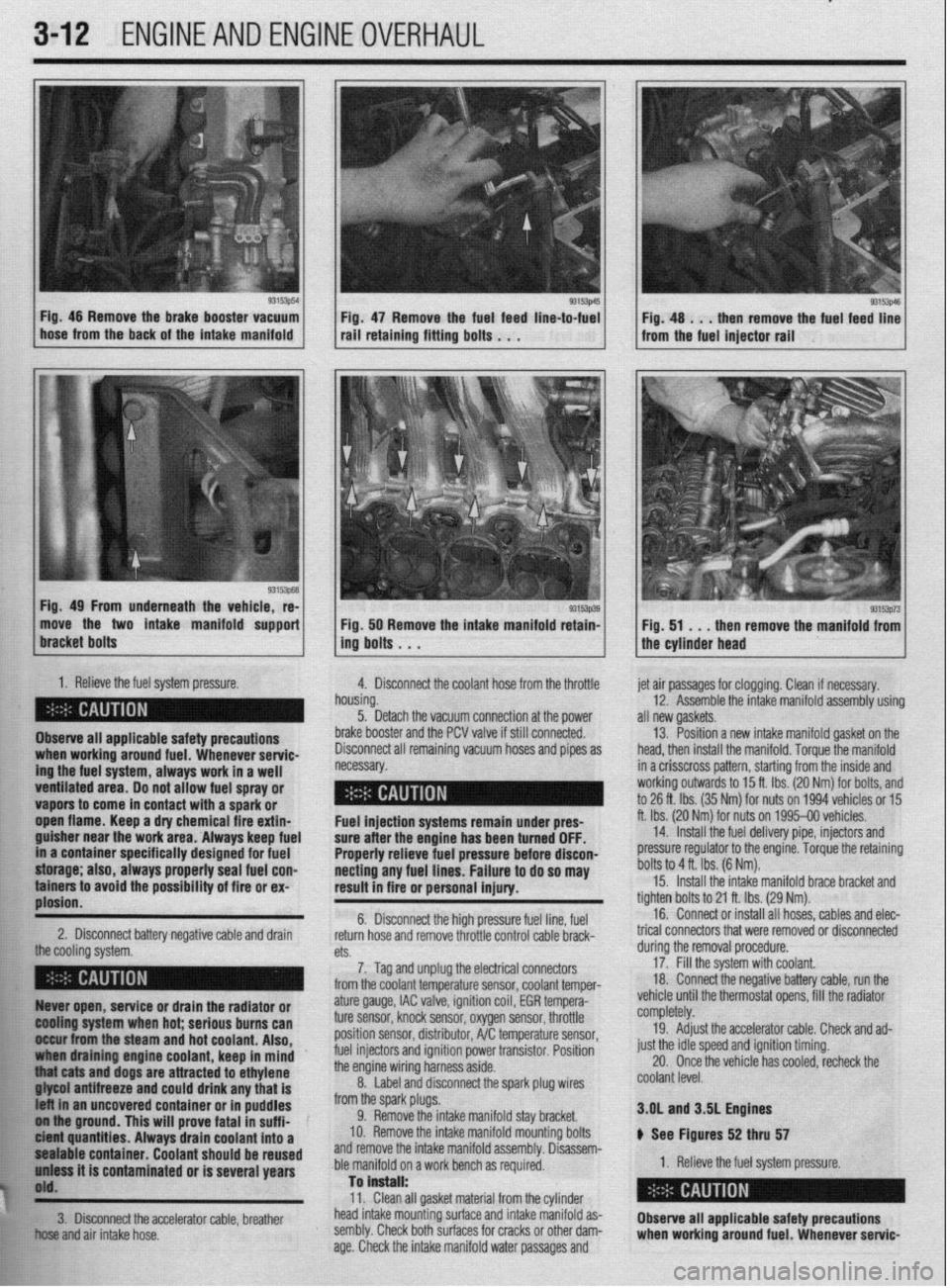
) See Figures 33 thru 51
93153p37 Fig. 33 Detach the A/C temp electrical con- 1
Page 73 of 408
.
3-12 ENGINEANDENGINEOVERHAUL
93153p54
1
L Fig. 46 Remove the brake booster vacuum
hose from the back of the intake manifold Fig 47 Remove the fuel feed line-to-fuel rail’retaini”g fitti”g bo,ts . . .
Fig. 49 From underneath the vehicle, re-
move the two intake manifold support
1. Relieve the fuel system pressure.
4. Disconnect the coolant hose from the throttle
Observe all applicable safety precautions
ing the fuel system, always work in a well when working around fuel. Whenever servic-
ventilated area. Do not allow fuel spray or - __.
vapors to come in contact with a spark or
._
open flame. Keep a dry chemical fire extin-
guisher near the work area. Always keep fuel
in a container specifically designed for fuel
storage; also, always properly seal fuel con-
tainers to avoid the possibility of fire or ex-
plosion.
2. Disconnect battery negative cable and drain
the cooling rtfctnm 93153p39 Fig. 50 Remove the intake manifold retain-
ing bolts . . .
h
n ousing.
5. Detach the vacuum connection at the power
b
rake booster and the PCV valve if still connected.
C lisconnect all remaining vacuum hoses and pipes as
ecessary. et air passages for clogging. Clean if necessary.
12. Assemble the intake manifold assembly using
III new gaskets.
13. Position a new intake manifold gasket on the
lead, then install the manifold. Torque the manifold
n a crisscross pattern, starting from the inside and
vorking outwards to 15 ft. Ibs. (20 Nm) for bolts, and
o 26 ft. Ibs. (35 Nm) for nuts on 1994 vehicles or 15
t. Ibs. (20 Nr$ for nuts on 1995-00 vehicles.
14. Install the fuel delivery pipe, injectors and
xessure regulator to the engine. Torque the retaining
)olts to 4 ft. Ibs. (6 Nm). Fuel injection systems remain under pres- f
sure after the engine has been turned OFF.
Properly relieve fuel pressure before discon-
necting any fuel lines. Failure to do so may [
result in fire or personal injury.
t 6. Disconnect the high pressure fuel line, fuel
return hose and remove throttle control cable brack- t
n+C.
cm. durino the removal orocedure. 15. Install the intake manifold brace bracket and
ighten bolts to 21 ft. Ibs. (29 Nm).
16. Connect or install all hoses, cables and elec-
rical connectors that were removed or disconnected
7. Tag and unplug the electrical connectors
from the coolant temperature sensor, coolant temper- 17: Fill the system with coolant.
18 Connect the negative battery cable, run the
, . : .., ,, ., , ,
,,,, ,. ,.
93153p73 Fig. 51 . . .
then remove the manifold from
the cylinder head
Ruver open, service or drain the radiator or
@Ming system when hot; serious burns can
II&ur from the steam and hot coolant. Also,
draining engine coolant, keep in mind ’
j “thiat cats and dogs are attracted to ethylene
. . . ..____ “..” 11_,1 -...... any that is
t uncovered container or in puddles
FE ol iha ground. This will prove fatal in suff i-
k ici?M quantities. Always drain coolant into a
$1 pealable container. Coolant should be reused
h’ uniass it is contaminated or is several years
j$O'd.
**w
ature gauge, IAC valve, ignition coil, EGR tempera-
ture sensor, knock sensor, oxygen sensor, throttle
position sensor, distributor, A/C temperature sensor,
fuel injectors and ignition power transistor. Position
the engine wiring harness aside.
8. Label and disconnect the spark plug wires
from the spark plugs.
9. Remove the intake manifold stay bracket.
IO. Remove the intake manifold mounting bolts
and remove the intake manifold assembly. Disassem-
ble manifold on a work bench as required.
Tan is”.+..ll. vemcle unrn me mermosrar opens, ml tne raalaror
completely.
19. Adjust the accelerator cable. Check and ad-
just the idle speed and ignition timing.
20. Once the vehicle has cooled, recheck the
coolant level.
3.OL and 3SL Engines
ti See Figures 52 thru 57
1. Relieve the fuel system pressure.
W.>. Clean all gasket material from the cylinder
!&S head intake mounting surface and intake manifold as-
fir!: 3. Disconnect the accelerator cable, breather
Observe all applicable safety precautions
El .;,
+w..” and air intake hose. sembly. Check both surfaces for cracks or other dam-
age. Check the intake manifold water passages and when working around fuel. Whenever servic-
Page 74 of 408
ENGINEANDENGINEOVERHAUL 3-13
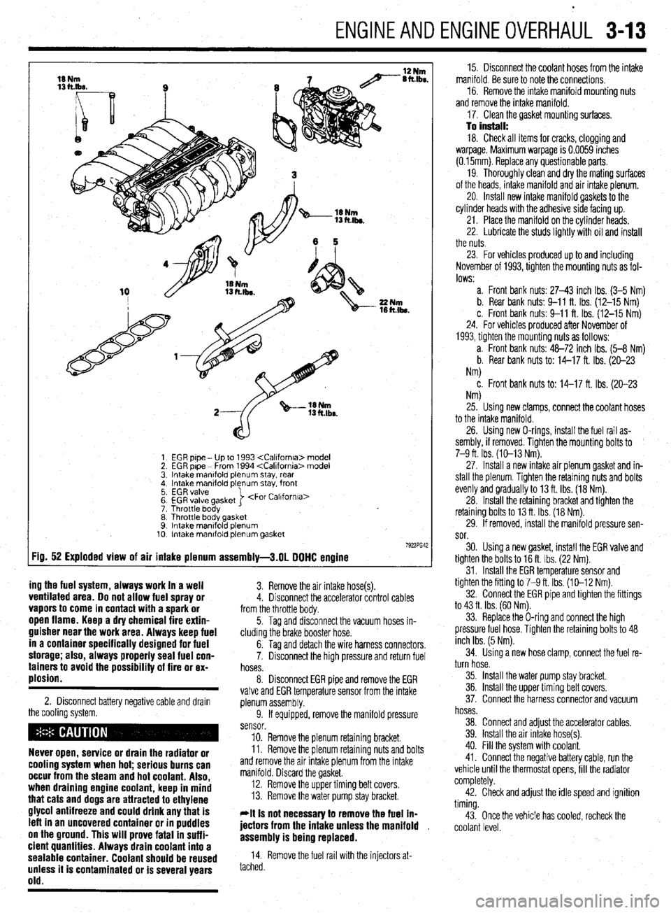
EGR pipe - Up to 1993
EGR pipe - From 1994
Intake manlfold plenum stay, rear
Intake manifold plenum stay. front
EGR valve
EGR valve gasket
Throttle body >
Throttle body gasket
Intake mantfold plenum
Intake manifold plenum gasket
:ig. 52 Exploded view of air intake plenum assembly-3.01 DOHC engine
ing the fuel system, always work in a well
3. Remove the air intake hose(s). ventilated area. Do not allow fuel spray or 4. Disconnect the accelerator control cables vapors to come in contact with a spark or from the throttle body. open flame. Keep a dry chemical fire extin-
guisher near the work area. Always keep fuel
in a container specifically designed for fuel
storage; also, always properly seal fuel con-
tainers to avoid the possibility of fire or ex-
plosion.
2. Disconnect battery negative cable and drawn
the cooling system.
Never open, service or drain the radiator or
cooling system when hot; serious burns can
occur from the steam and hot coolant. Also,
when draining engine coolant, keep in mind
that cats and dogs are attracted to ethylene
glycol antifreeze and could drink any that is
left in an uncovered container or in puddles
on the ground. This will prove fatal in suffi-
cient quantities. Always drain coolant into a
sealable container. Coolant should be reused
unless it is contaminated or is several years
old.
5. Tag and disconnect the vacuum hoses in-
cluding the brake booster hose.
6. Tag and detach the wire harness connectors,
7. Disconnect the high pressure and return fuel
hoses.
8. Disconnect EGR pipe and remove the EGR
valve and EGR temperature sensor from the intake
plenum assembly.
9. If equipped, remove the manifold pressure
sensor.
10. Remove the plenum retaining bracket.
11. Remove the plenum retaining nuts and bolts
and remove the air intake plenum from the intake
manifold. Discard the gasket.
12. Remove the upper timing belt covers.
13. Remove the water pump stay bracket.
*It is not necessav to remove the fuel ln-
jectors from the intake unless the manifold ,
assembly is being replaced.
14. Remove the fuel rail with the injectors at-
tached. 15. Disconnect the coolant hoses from the intake
manifold. Be sure to note the connections.
16. Remove the intake manifold mounting nuts
and remove the intake manifold.
17. Clean the gasket mounting surfaces.
To install: 18. Check all items for cracks, clogging and
warpage. Maximum warpage is 0.0059 inches
(0.15mm). Replace any questionable parts.
19. Thoroughly clean and dry the mating surfaces
of the heads, intake manifold and air intake plenum.
20. Install new intake manifold gaskets to the
cylinder heads with the adhesive side facing up.
21. Place the manifold on the cylinder heads.
22. Lubricate the studs lightly with oil and install
the nuts.
23. For vehicles produced up to and including
November of 1993, tighten the mounting nuts as fol-
lows:
a. Front bank nuts: 27-43 inch Ibs. (3-5 Nm)
b. Rear bank nuts: 9-11 ft. Ibs. (12-15 Nm)
c. Front bank nuts: 9-11 ft. Ibs. (12-15 Nm)
24. For vehicles produced after November of
1993, tighten the mounting nuts as follows:
a. Front bank nuts: 48-72 inch Ibs. (5-8 Nm)
b. Rear bank nuts to: 14-17 ft. Ibs. (20-23
Nm)
c. Front bank nuts to: 14-17 ft. Ibs. (20-23
NM
25. Using new clamps, connect the coolant hoses
to the intake manifold.
26. Using new O-rings, install the fuel rail as-
sembly, if removed. Tighten the mounting bolts to
7-9 ft. Ibs. (10-13 Nm).
27. Install a new intake air plenum gasket and in-
stall the plenum. Tighten the retaining nuts and bolts
evenly and gradually to 13 ft. Ibs. (18 Nm).
28. Install the retaining bracket and tighten the
retaining bolts to 13 ft. Ibs. (18 Nm).
29. If removed, install the manifold pressure sen-
sor.
30. Using a new gasket, install the EGR valve and
tighten the bolts to 16 ft. Ibs. (22 Nm).
31. Install the EGR temperature sensor and
tighten the fitting to 7-9 ft. Ibs. (10-12 Nm).
32. Connect the EGR pipe and tighten the fittings
to 43 ft. Ibs. (60 Nm).
33. Replace the O-ring and connect the high
pressure fuel hose. Tighten the retaining bolts to 48
inch Ibs. (5 Nm).
34. Using a new hose clamp, connect the fuel re-
turn hose.
35. Install the water pump stay bracket.
36. Install the upper timing belt covers.
37. Connect the harness connector and vacuum
hoses.
38. Connect and adjust the accelerator cables.
39. Install the air intake hose(s).
40. Fill the system with coolant.
41. Connect the negative battery cable, run the
vehicle until the thermostat opens, fill the radiator
completely.
42. Check and adjust the idle speed and ignition
timing.
43. Once the vehicle has cooled, recheck the
coolant level.
Page 85 of 408
3-24 ENGINEANDENGINEOVERHAUL
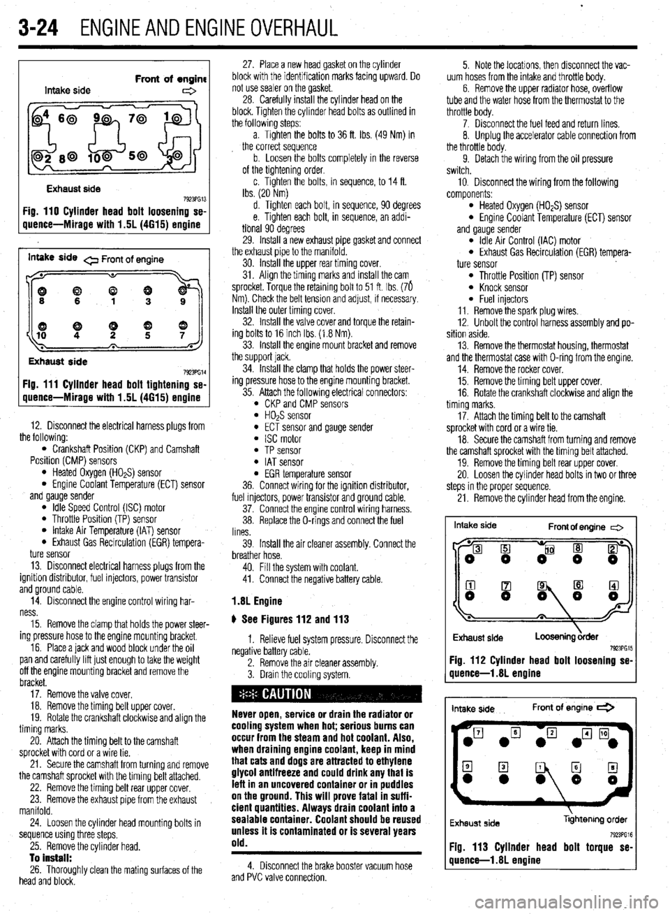
Intake side Front of engine
e
Exhaust side
7923PG13 Fig. 110 Cylinder head bolt loosening se-
uuence-Mirage with 1.5L (4615) ermine
inwe side 0 Front of engine
((9
Exhaust side
7923PG14 Fig. 111 Cyllnder head bolt tightening se-
quence-Mirage with 1.5L (4615) engine
12. Disconnect the electrical harness plugs from
the following:
l Crankshaft Position (CKP) and Camshaft
Position (CMP) sensors
l Heated Oxygen (HO*S) sensor l Engine Coolant Temperature (ECT) sensor
and gauge sender
l Idle Speed Control (ISC) motor l Throttle Position (TP) sensor l Intake Air Temperature (IAT) sensor l Exhaust Gas Recirculation (EGR) tempera-
ture sensor
13. Disconnect electrical harness plugs from the
ignition distributor, fuel injectors, power transistor
and ground cable.
14. Disconnect the engine control wiring har-
ness.
15. Remove the clamp that holds the power steer-
ing pressure hose to the engine mounting bracket.
16. Place a jack and wood block under the oil
pan and carefully lift just enough to take the weight
off the engine mounting bracket and remove the
bracket.
17. Remove the valve cover.
18. Remove the timing belt upper cover.
19. Rotate the crankshaft clockwise and align the
timing marks.
20. Attach the timing belt to the camshaft
sprocket with cord or a wire tie.
21. Secure the camshaft from turning and remove
the camshaft sprocket with the timing belt attached.
22. Remove the timing belt rear upper cover.
23. Remove the exhaust pipe from the exhaust
manifold.
24. Loosen the cylinder head mounting bolts in
sequence using three steps.
25. Remove the cylinder head.
To install:
26. Thoroughly clean the mating surfaces of the
head and block. 27. Place a new head gasket on the cylinder
block with the identification marks facing upward. Do
not use sealer on the gasket.
28. Carefully install the cylinder head on the
block. Tighten the cylinder head bolts as outlined in
the followlng steps:
a. Tighten the bolts to 36 ft. Ibs. (49 Nm) in
the correct sequence
b. Loosen the bolts completely in the reverse
of the tightening order,
c. Tighten the bolts, in sequence, to 14 ft.
Ibs. (20 Nm)
d. Tighten each bolt, in sequence, 90 degrees
e. Tighten each bolt, in sequence, an addi-
tional 90 degrees
29. Install a new exhaust pipe gasket and connect
the exhaust pipe to the manifold.
30. Install the upper rear timing cover.
31. Align the timing marks and install the cam
sprocket. Torque the retaining bolt to 51 ft. Ibs. (76
Nm). Check the belt tension and adjust, if necessary.
Install the outer timing cover.
32. Install the valve cover and torque the retain-
ing bolts to 16 inch Ibs. (1.8 Nm).
33. Install the engine mount bracket and remove
the support jack.
34. Install the clamp that holds the power steer-
ing pressure hose to the engine mounting bracket.
35. Attach the following electrical connectors:
l CKP and CMP sensors l HOPS sensor l ECT sensor and gauge sender l ISC motor l TP sensor l IAT sensor l EGR temperature sensor
36. Connect wiring for the ignition distributor,
fuel injectors, power transistor and ground cable.
37. Connect the engine control wiring harness.
38. Replace the O-rings and connect the fuel
lines.
39. Install the air cleaner assembly. Connect the
breather hose.
40. Fill the system with coolant.
41. Connect the negative battery cable.
1.8L Engine
# See Figures 112 and 113
1. Relieve fuel system pressure. Disconnect the
negative battery cable.
2. Remove the air cleaner assembly.
3. Drain the cooling system.
Never open, service or drain the radiator or
cooling system when hot; serious burns can
occur from the steam and hot coolant. Also,
when draining engine coolant, keep in mind
that cats and dogs are attracted to ethylene
glycol antifreeze and could drink any that is
lefl in an uncovered container or in puddles
on the ground. This will prove fatal in suffi-
cient quantities. Always drain coolant into a
sealable container. Coolant should be reused
unless it is contaminated or is several years
old.
4. Disconnect the brake booster vacuum hose
and PVC valve connection. 5. Note the locations, then disconnect the vac-
uum hoses from the intake and throttle body.
6. Remove the upper radiator hose, overflow
tube and the water hose from the thermostat to the
throttle body.
7. Disconnect the fuel feed and return lines.
8. Unplug the accelerator cable connection from
the throttle body.
9. Detach the wiring from the oil pressure
switch.
10, Disconnect the wiring from the following
components:
l Heated Oxygen (HO*S) sensor l Engine Coolant Temperature (ECT) sensor
and gauge sender
l Idle Air Control (IAC) motor l Exhaust Gas Recirculation (EGR) tempera-
ture sensor
l Throttle Position (TP) sensor l Knock sensor l Fuel injectors
11. Remove the spark plug wires.
12. Unbolt the control harness assembly and po-
sition aside.
13. Remove the thermostat housing, thermostat
and the thermostat case with O-ring from the engine.
14. Remove the rocker cover.
15. Remove the timing belt upper cover.
16. Rotate the crankshaft clockwise and align the
timing marks.
17. Attach the timing belt to the camshaft
sprocket with cord or a wire tie.
18. Secure the camshaft from turning and remove
the camshaft sprocket with the timing belt attached.
19. Remove the timing belt rear upper cover.
20. Loosen the cylinder head bolts in two or three
steps in the proper sequence.
21. Remove the cylinder head from the engine.
Intake side
Front of engine c=>
I
Exhaust side
Loosening &der 7923PG15 Fig. 112 Cylinder head bolt loosening se-
quence-l .8L engine
intake side Front of engine *
Exhaust side libhtenng order
Fig. 113 Cylinder head bolt torque se-
quence-l .8L engine