1900 MITSUBISHI DIAMANTE brake light
[x] Cancel search: brake lightPage 339 of 408
BRAKiS 9-3
simple and efficient. A vacuum diaphragm is located gine. Have an assistant observe the brake lights at the
on the front of the master cylinder and assists the dri- rear of the vehicle while you push on the brake pedal.
ver in applying the brakes, reducing both the effort The lights should come on just as the brake pedal
and travel he must put into moving the brake pedal. passes the point of free play.
The vacuum diaphragm housing is normally con- 9.
Adjust the brake light switch as necessary. The
netted to the intake manifold by a vacuum hose. A small amount of free play in the
pedal should not
check valve is placed at the point where the hose en-
ters the diaphragm housing, so that during periods
Of low manifold vacuum brakes assist will not be lost.
Depressing the brake pedal closes off the vacuum
source and allows atmospheric pressure to enter on
one side of the diaphragm. This causes the master
cylinder pistons to move and apply the brakes. When
the brake pedal is released, vacuum is applied to
REMOVAL &INSTALLATION
both sides of the diaphragm and springs return the
diaphragm and master cylinder pistons to the re- ) See Figures 2 thru 10
leased position.
If the vacuum supply fails, the brake pedal rod will
contact the end of the master cylinder actuator rod
and the system will apply the brakes without any
power assistance. The driver will notice that much
higher pedal effort is needed to stop the car and that
the pedal feels harder than usual.
Vacuum leak Test
1. Operate the engine at idle without touching the
brake pedal for at least one minute.
2. Turn off the engine and wait one minute.
3. Test for the presence of assist vacuum by de-
pressing the brake pedal and releasing it several
3 MASTER N- 188A11Ly
times. If vacuum is present in the system, light appli- . KLNsIMEm 0s CLWRANCE
BETWEEN BRAKE WOSTER
cation will produce less and less pedal travel. If there PUSHROO AN0 PRIMARY PISTCU
is no vacuum, air is leaking into the system.
System Operation Test
1. With the engine OFF, pump the brake pedal
until the supply vacuum is entirely gone.
2. Put light, steady pressure on the brake pedal.
3. Start the engine and let it idle. If the system is
operating correctly, the brake pedal should fall to-
ward the floor if the constant pressure is maintained.
Power brake systems may be tested for hydraulic
leaks just as ordinary systems are tested.
REMOVAL&INSTALLATION
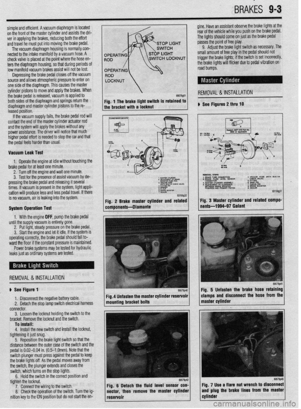
$ See Figure 1
1. Disconnect the negative battery cable.
2. Detach the stop lamp switch electrical harness
connector.
3. Loosenthe locknut holding the switch to the
bracket. Remove the locknut and the switch.
To install:
4.
Install the new switch and install the locknut,
tightening it just snug.
5. Reposition the brake light switch so that the
distance between the outer case of the switch and the
pedal is 0.02-0.04 in. (0.5-l .Omm). Note that the
switch plunger must press against the pedal to keep
the brake lights off. As the pedal moves away from
the switch, the plunger extends and closes the
switch, which turns on the stop lights.
6.
Hold the switch in the correct position and
tighten the locknut.
7. Connect the wiring to the switch.
8. Check the operation of the switch. Turn the ig-
nition key to the ON position but do not start the en-
Page 340 of 408
9-4 BRAKES
Fig 8 Unfasten the master cylinder-to-
power booster retaining nuts . . . F57g’6~ Fig. 9 . . . then remove the master cylinder
assembly from the vehicle Fig. 10 The brake booster pushrod and prf-
mary piston clearance (A) must be adjusted
1. Disconnect the negative battery cable.
2. Remove the master cylinder reservoir cap,
then use a clean turkey baster or equivalent to siphon
out as much fluid as possible and place in a suitable
container. Install the cap.
Brake fluid contains polyglycol ethers and
polyglycols. Avoid contact with the eyes and
wash your hands thoroughly after handling
brake fluid. If you do get brake fluid in your
eyes, flush your eyes with clean, running wa-
ter for 15 minutes. If eye irritation persists,
or if you have taken brake fluid internally,
IMMEDIATELY seek medical assistance.
3. Disconnect and plug the lines from the brake
master cylinder reservoir.
4. Detach the fluid level sensor connector, un-
fasten the retainers, then remove the master cylinder
reservoir.
5. For vehicles equipped with manual transaxle,
remove the clutch master cylinder reservoir bracket.
6. Disconnect and plug the brake lines from the
master cylinder.
7. Unfasten the master cylinder-to-power
booster retainino nuts, then remove the master cvlin- ante value will become 0.004-0.012 in.
(0.1-0.3mm).
9. install the master cylinder to the brake
booster, then install the retaining nuts. Tighten the
nuts to 7 ft. Ibs. (10 Nm).
10. Install the master cylinder reservoir, securing
the retainers.
11. Attach the fluid level sensor connector, then
unplug and connect the fluid lines to the reservoir.
12. The remainder of installation is the reverse of
the removal procedure. Fill the reservoir with the
proper type and amount of DOT 3 brake fluid from a
fresh, sealed container.
I l
Clean, high quality brake fluid is essential to
the safe and proper operation of the brake
system. You should always buy the highest
quality brake fluid that is available. If the
brake fluid becomes contaminated, drain and
flush the system, then refill the master cylin-
der with new fluid. Never reuse any brake
fluid. Any brake fluid that is removed from
the system should be discarded. Also, do not
allow any brake fluid to come in contact with
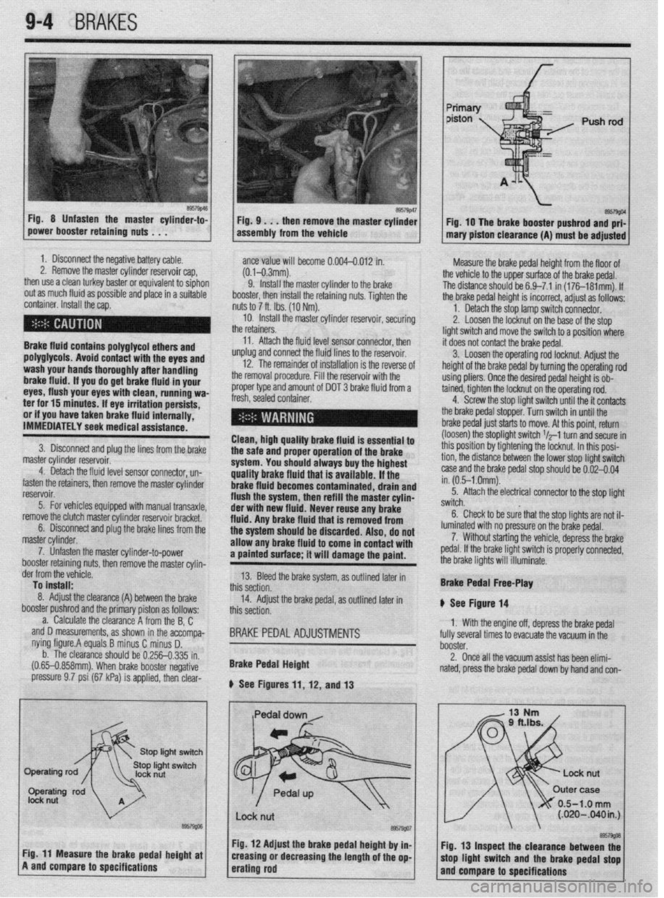
a painted surface; it will damage the paint. Measure the brake pedal height from the floor of
the vehicle to the upper surface of the brake pedal.
The distance should be 6.9-7.1 in (176181mm). If
the brake pedal height is incorrect, adjust as follows:
1. Detach the stop lamp switch connector.
2. Loosen the locknut on the base of the stop
light switch and move the switch to a position where
it does not contact the brake pedal.
3. Loosen the operating rod locknut. Adjust the
height of the brake pedal by turning the operating rod
using pliers. Once the desired pedal height is ob-
tained, tighten the locknut on the operating rod.
4. Screw the stop light switch until the it contacts
the brake pedal stopper. Turn switch in until the
brake pedal just starts to move. At this point, return
(loosen) the stoplight switch $-1 turn and secure in
this position by tightening the locknut. In this posi-
tion, the distance between the lower stop light switch
case and the brake pedal stop should be 0.02-0.04
in. (0.5-l .Omm).
5. Attach the electrical connector to the stop light
switch.
6. Check to be sure that the stop lights are not il-
luminated with no pressure on the brake pedal.
7. Without starting the vehicle, depress the brake
pedal. If the brake light switch is properly connected,
the brake lights will illuminate.
der from the vefiicle.
To install:
8. Adjust the clearance (A)
booster pushrod ant
a. Calculate tl -,
between the brake
I the primary piston as follows:
le clearance A from the B, C
accompa-
i D.
I.335 in.
negative and D measurements, as shown in the
nying figure.A equals B minus C minus
b. The clearance should be 0.256-t
(0.65-0.858mm). When brake booster I
pressure 9.7 psi (67 kPa) is applied, then clear- 13. Bleed the brake system, as outlined later in
this section.
14. Adjust the brake pedal, as outlined later in
this section.
BRAKE PEDAL ADJUSTMENTS
Brake Pedal Height
b See Figures 11, 12, and 13 Brake Pedal Free-Play
II See Figure 14
1. With the engine off, depress the brake pedal
fully several times to evacuate the vacuum in the
booster.
2. Once all the vacuum assist has been elimi-
nated, press the brake pedal down by hand and con-
/
0.5-1.0 mm (.020-B40in.J I
I
I I
Fig. 12 Adjust the brake pedal height by in- I I.
@57w
Cir 44 “a*., .._^ *I.- 9.--l,- ---I-* L-@-L. -I Fig. 13 Inspect the clearance between thf . . - _-.L -*.a- - . . * _ . . . . ._ . rly. I I rnca~urc we urime peoai nefgnr ar
A and compare to specifications creasmg or aecreasing the lengrn or me op-
erating rod mop llgnt WItCh arm the brake pedal stop
and compare to specifications
Page 341 of 408
BRAKES 9-5
Inspect brake pedal free-play
firm that the amount of movement before resistance
is felt is within 0.1-0.3 in. (3-8mm).
3. If the free-play is less than desired, confirm
that the brake light switch is in proper adjustment.
4. If there is excessive free-play, look for wear or
play in the clevis pin and brake pedal arm. Replace
worn parts as required and recheck brake pedal free-
Play*
REMOVAL &INSTALLATION '
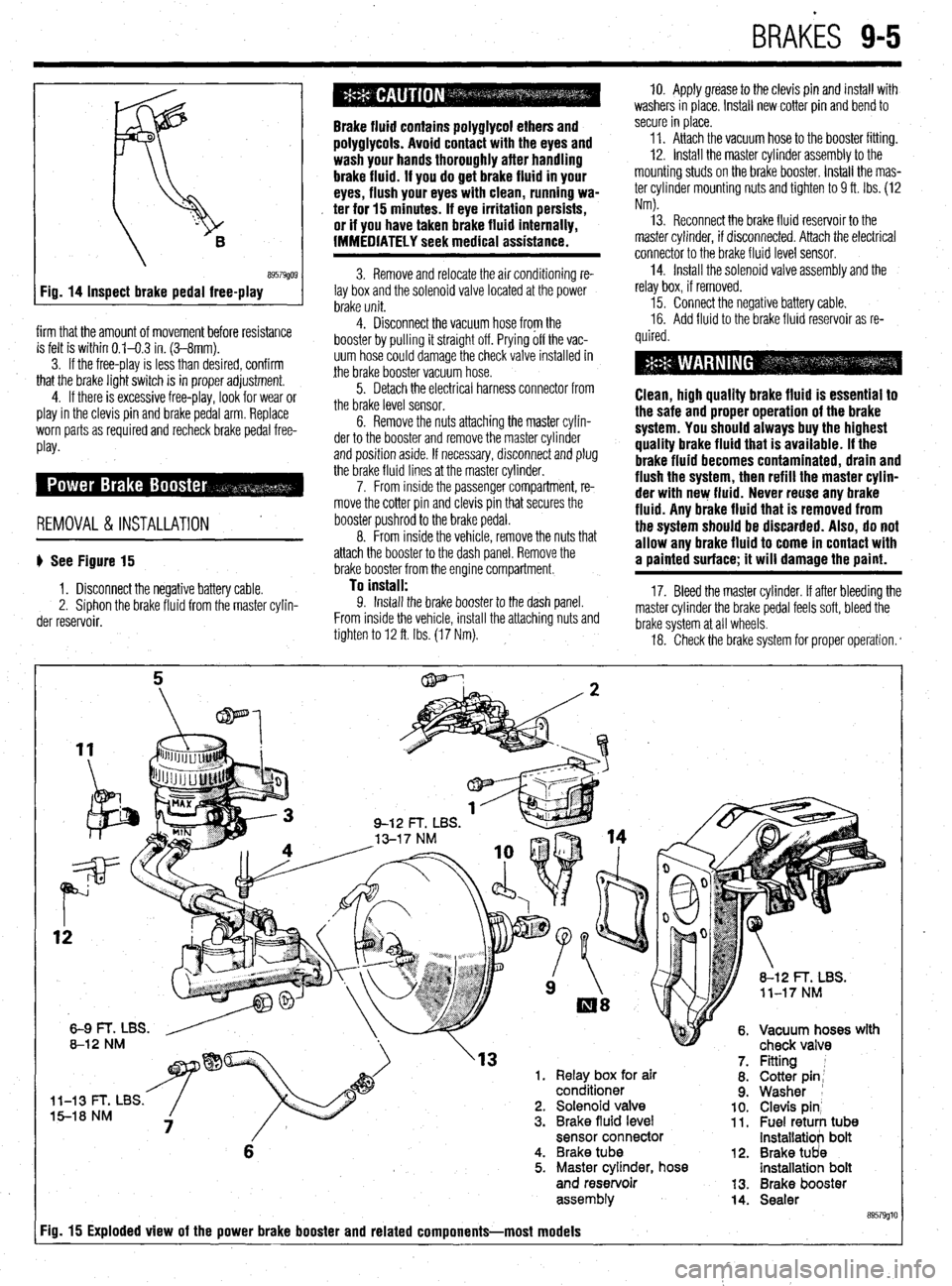
b See Figure 15
1. Disconnect the negative battery cable.
2. Siphon the brake fluid from the master cylin-
der reservoir.
Brake fluid contains polyglycol ethers and
polyglycols. Avoid contact with the eyes and
wash your hands thoroughly after handling
brake fluid. If you do get brake fluid in your
eyes, flush your eyes with clean, running wa-
. ter for 15 minutes. If eye irritation persists,
or if you have taken brake fluid internally,
IMMEDIATELY seek medical assistance.
3. Remove and relocate the air conditioning re-
lay box and the solenoid valve located at the power
brake unit.
4. Disconnect the vacuum hose from the
booster by pulling it straight off. Prying off the vac-
uum hose could damage the check valve installed in
the brake booster vacuum hose.
5. Detach the electrical harness connector from
the brake level sensor.
6. Remove the nuts attaching the master cylin-
der to the booster and remove the master cylinder
and position aside. If necessary, disconnect and plug
the brake fluid lines at the master cylinder.
7. From inside the passenger compartment, re-
move the cotter pin and clevis pin that secures the
booster pushrod to the brake pedal.
8. From inside the vehicle, remove the nuts that
attach the booster to the dash panel. Remove the
brake booster from the engine compartment.
To install: 9. Install the brake booster to the dash panel.
From inside the vehicle, install the attaching nuts and
tighten to 12 ft. Ibs. (17 Nm). 10. Apply grease to the clevis pin and install with
washers in place. Install new cotter pin and bend to
secure in place.
11. Attach the vacuum hose to the booster fitting.
12. Install the master cylinder assembly to the
mounting studs on the brake booster. Install the mas-
ter cylinder mounting nuts and tighten to 9 ft. Ibs. (12
Nm).
13. Reconnect the brake fluid reservoir to the
master cylinder, if disconnected. Attach the electrical
connector to the brake fluid level sensor.
14. Install the solenoid valve assembly and the
relay box, if removed.
15. Connect the negative battery cable.
16. Add fluid to the brake fluid reservoir as re-
quired.
Clean, high quality brake fluid is essentlal to
the safe and proper operation of the brake
system. You should always buy the highest
quality brake fluid that is available. If the
brake fluid becomes contaminated, drain and
flush the system, then refill the master cylin-
der with new fluid. Never reuse any brake
fluid. Any brake fluid that is removed from
the system should be discarded. Also, do not
allow any brake fluid to come in contact with
a painted surface; it will damage the paint.
17. Bleed the master cylinder. If after bleeding the
master cylinder the brake pedal feels soft, bleed the
brake system at all wheels.
18. Check the brake system for proper operation. *
rn( mr
'13 1. Relay box for air
conditioner
l-13 t- I, Ltx5. 5-18 NM 2. Solenoid valve
3. Brake fluid level
sensor connector
6 4. Brake tube
5. Master cylinder, hose
and reservoir
assem biy
Fig. 15 Exploded view of the power brake booster and related components-most models
12.
13.
14. Fitting 1
Cotter pin;
Washer 1
Clevis pin’ Fuel retuti tub8 installatiob bolt
Brake tUd8 installatioh bolt
Brake booster
Sealer
89579glt
Page 345 of 408
2. Raise the vehicle and support safely.
3. Remove the appropriate tire and wheel as-
semblies. 11. Road test the vehicle and check brakes for
proper operation. *Be careful that the piston boot does not be-
come caught when lowering the caliper onto
+ha n,.nnnr) lh nnt t&at thm hr&a hnra rlnr-
4. Remove the calmer auide and lock Dins and
REAR
lift the caliper assembly’from the caliper support. Tie
the caliper
out of the way using wire. 00 not allow the
caliper to hang by the brake line.
*On some vehicles, the caliper can be
flipped up by leaving the upper pin in place
and usinu it as a oivot ooint.
---- sa - . -.
5. Remove the brake pads, spring clip and
cl7knr T&n nn+n ,-A nrdtinninntn sir-4 inc+alhtinn
u See Figures 32 and 34 13. Lubricate, install and tighten the lower pin.
*
14. Install the tire and wheel assemblies. Lower
1, Remove some of the brake fluid from the the vehicle.
master cylinder reservoir. The reservoir should be no 15. Test the brakes for proper operation:
more than half full. When the p istons are depressed
into the calioers. excess fluid
3 111,113. ,(lhC ,,“LC “I p”3”‘““H’y I” a,u IIIaLcuIaLt”II. 6. Install two wheel lug nuts onto the studs and
:
lightly tighten. This is done to hold the disc on the
hub.
To install:
7. Use a large C-clamp to compress piston(s)
back into caliper bore. On two piston calipers both
pistons will have to be retracted together.
8. Lubricate slide points and install the brake
pads, shims and spring clip ont- +‘- --“n-* n**nnnA reservoir. /ill flow up into the
2. Raise the vehicle and support safely.
s tire and wheel as- 3. Remove the appropriate
semblies.
4. Loosen the parking bra
from inside the vehicle.
5. Disconnect the parking brake cable end in-
stalled to the rear brake caliper assembly.
6. Remove the caliper lower pin and swing the
caliper assembly upwards. Tie the caliper out of the
way using wire. Dlamante and 1994-00 Galant
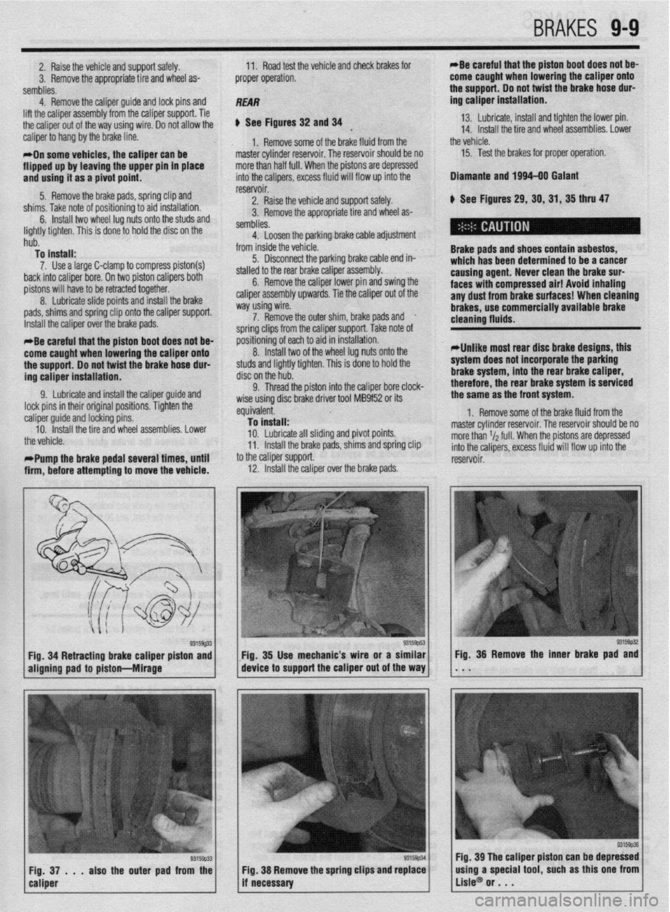
k See Figures 29,30,31,35 thru 47
Brake pads and shoes contain asbestos,
which has been determined to be a cancer
causing agent. Never clean the brake sur-
faces with compressed air! Avoid inhaling
any dust from brake surfaces! When cleaning
brakes. use commerciallv avallable brake Ike cable adjustment
Install the caliper over the brake ,..uuG. 7. Remove the outer shim, brake pads and
.
ie caliper support. Take note of soring clips from tl
nositibning of eact
8
IndalI twn cleaning flutds. -
*Be careful that the piston boot does not be-
come caught when lowering the caliper onto
the support. Do not twist the brake hose dur-
ing caliper installation. I to aid in installation.
“. llluLull L..V of the wheel lug nuts onto the
studs and lightly tighten. This is done to hold the
disc on the hub.
Cl Thrm-l the nictnn into thP r!alinar hnre rlnrk-
*Unlike most rear disc brake designs, this
system does not incorporate the parking
brake system, into the rear brake caliper,
therefore, the rear brake system is serviced
9. Lubricate and install the caliper guide and
lock pins in their original positions. Tighten the
: caliper guide and locking pins.
10. Install the tire and wheel assemblies. Lower
the vehicle.
t *Pump the brake pedal several times, until
i
firm, before attempting to move the vehicle. V. ,,,lV”” ,,,V ~,“L”,’ III1” .IIV “..*.prv, ““I., “.“-a.
wise using disc brake driver tool MB9f52 or its
equivalent.
To install:
10. Lubricate all sliding and pivot points.
11. Install the brake pads, shims and spring clip
to the caliper support.
12. Install the caliper over ”
’ -’ ---I~ me oraxe paas. the same as the front system.
1. Remove some of the brake fluid from the
master cylinder reservoir. The reservoir should be no
more than r/a full. When the pistons are depressed
into the calipers, excess fluid will flow up into the
reservoir.
93159#2 Fig. 34 Retracting brake caliper piston and Fig. 35 Use mechanic’s wire or a similar
aligning pad to piston-hlirage device to support the caliper out of the way Fig. 36 Remove the inner brake pad and
. . .
93159p33 Fig, 37 . . . also the outer pad from the
caliper Fig. 39 The caliper piston can be depressed
Fig. 38 Remove the spring clips and replace
if necessary using a special tool, such as this one from
Lisle@ or . . .
Page 346 of 408
l
9-10 BRAKES
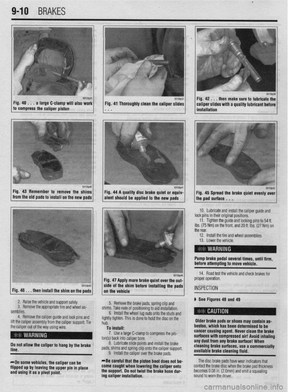
Fig. 40 . . . a large C-clamp will also work
to compress the caliper piston then make sure to lubricate the
Fig. 46
. . . then install the shim on the pads Fig. 47 Apply more brake quiet over the out-
/, the vehicle .Is/l*
wde of the sham before installing the pads
2. Raise the vehicle and support safely.
3. Remove the appropriate tire and wheel as-
semblies.
4. Remove the caliper guide and lock pins and
lift the caliper assembly from the caliper support. Tie
the caliper out of the way using wire.
( I ’ 5. Remove the brake pads, spring clip and
shims. Take note of positioning to aid installation.
6.
Do not allow the caliper to hang by the brake ’
line.
*On some vehicles, the caliper can be
flipped up by leaving the upper pin in place
and using it as a pivot point. Install the wheel lug nuts onto the studs and
lightly tighten. This is done to hold the disc on the
hub.
To install:
7. Use a large C-clamp to compress the pis-
ton(s) back into caliper bore.
_
8. Lubricate slide points and install the brake
pads, shims and spring clip onto the caliper support.
9. Install the caliper over the brake pads.
*Be careful that the piston boot
does not be- come caught when lowering the caliper onto
the support. Do not twist the brake hose dur-
ing caliper installation. Older brake pads or shoes may contain as-
bestos, which has been determined to be
cancer causing agent. Never clean the
brake
surfaces with compressed air! Avoid inhaling any dust from any brake surface! When
cleaning brake surfaces, use a commercially
available brake cleaning fluid. IO. Lubricate and install the caliper guide and
lock pins in their original positions.
11. Tighten the guide and locking pins to 54 ft.
Ibs. (75 Nm) on the front, and 20 ft. Ibs. (27 Nm) on
the rear,
12. install the tire and wheel assemblies.
13. Lower the vehicle.
Pump brake pedal several tlmes, until firm,
before attempting to move vehicle.
14. Road test the vehicle and check brakes for
proper operation.
INSPECTION
p See Figures 48 and 49
The disc brake pads have wear indicators that
contact the brake disc when the brake pad thickness
becomes 0.08 in. (2.0mm) and emit a squealing
sound to worn the driver.
Page 349 of 408
BRAKiS 9-13
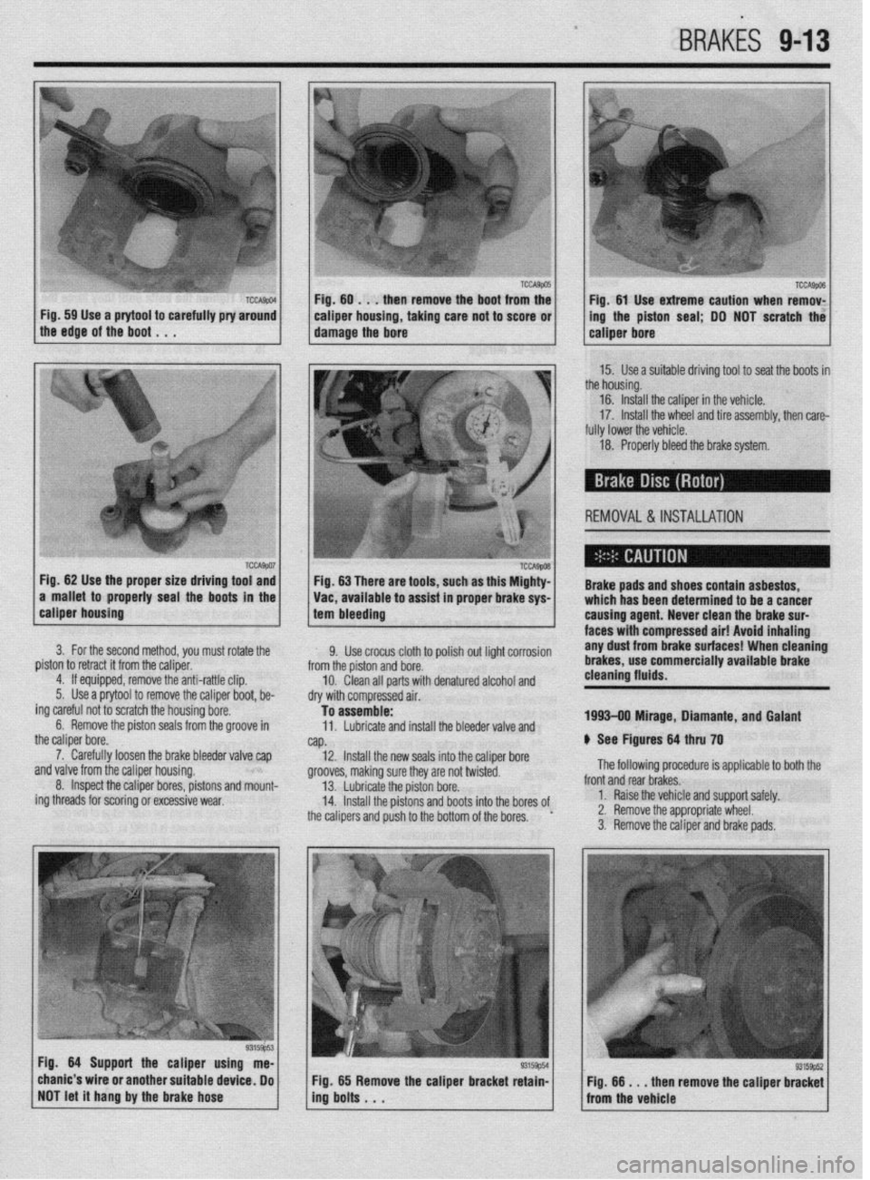
Fig. 59 Use a prytool to carefully pry around 1
the edge of the boot , , . caiper housing, taking care not to score or 1
damage the bore ing the piston seal; DO NOT scratch the
15. Use a suitable driving tool to seat the boots in
the housing.
16. Install the caliper in the vehicle.
17. Install the wheel and tire assembly, then care-
fully lower the vehicle.
18. Properly bleed the brake system.
REMOVAL &INSTALLATION
Fig. 62 Use the proper size driving tool and
a mallet to properly seal the boots in the Fig. 63 There are tools, such as this Mighty-
Vat, available to assist in proper brake sys- Brake pads and shoes contain asbestos,
which has been determined to be a cancer
calmer housino
1 tam hlasrlinn . --~-~~~v
3. For the second method, you must rotate the
piston to retract it from the caliper.
4. If equipped, remove the anti-rattle clip.
5. Use a prytool to remove the caliper boot, be-
ing careful not to scratch the housing bore.
6. Remove the piston seals from the groove in
the caliper bore.
7. Carefully loosen the brake bleeder valve cap
~nrl \I~IWJ frnm the r~linor hnlwinn
I causina aaent. LL.....” rlrr.. .I.,. l.uLr I..”
Yll” .UI”Y ll”lll LIIb rro,spl tI”“Jlly. 8. Inspect the caliper bores, pistons and mount-
ing threads for scoring or excessive wear,
--... -.---...= ’ I.twla lilci(lll Lllli uranl$ au,- faces with-compressed air! Avoid Inhaling
9. Use crocus cloth to polish out light corrosion any dust from brake surfaces! When cleaning
from the piston and bore. brakes, use commercially available brake
10. Clean all parts with denatured alcohol and cleaning fluids.
dry with compressed air.
To assemble:
11. Lubricate and install the bleeder valve and 1993-09 Mirage, Diamante, and Galant
NP. 6 See Figures 64 thru 70
12. Install the new seals into the caliper bore
nrnnlrhr m”lr;nn Clln-. M..-.., nrn n.4 h..‘“‘“~ The following procedure is applicable to both the ytvvvca, lllanllly 3”IC o,ey ale II”, IWI~LCL. 13. Lubricate the piston bore.
14. Install the pistons and boots into the bores of
the calipers and push to the bottom of the bores. ’ front and rear brakes.
1. Raise the vehicle and support safely.
2. Remove the appropriate wheel.
3. Remove the caliper and brake pads.
Fia. 64 Suoaarl the calmer usina me-
., -----= -..- chanic’s wire or another suitable device, Do
NOT let it hang by the brake hose Fig. 65 Remove the caliper bracket retain-
ing bolts . . . Fig. 66 m . . then remove the caliper bracket
from the vehicle
Page 350 of 408
l
9-14 BRAKES
-
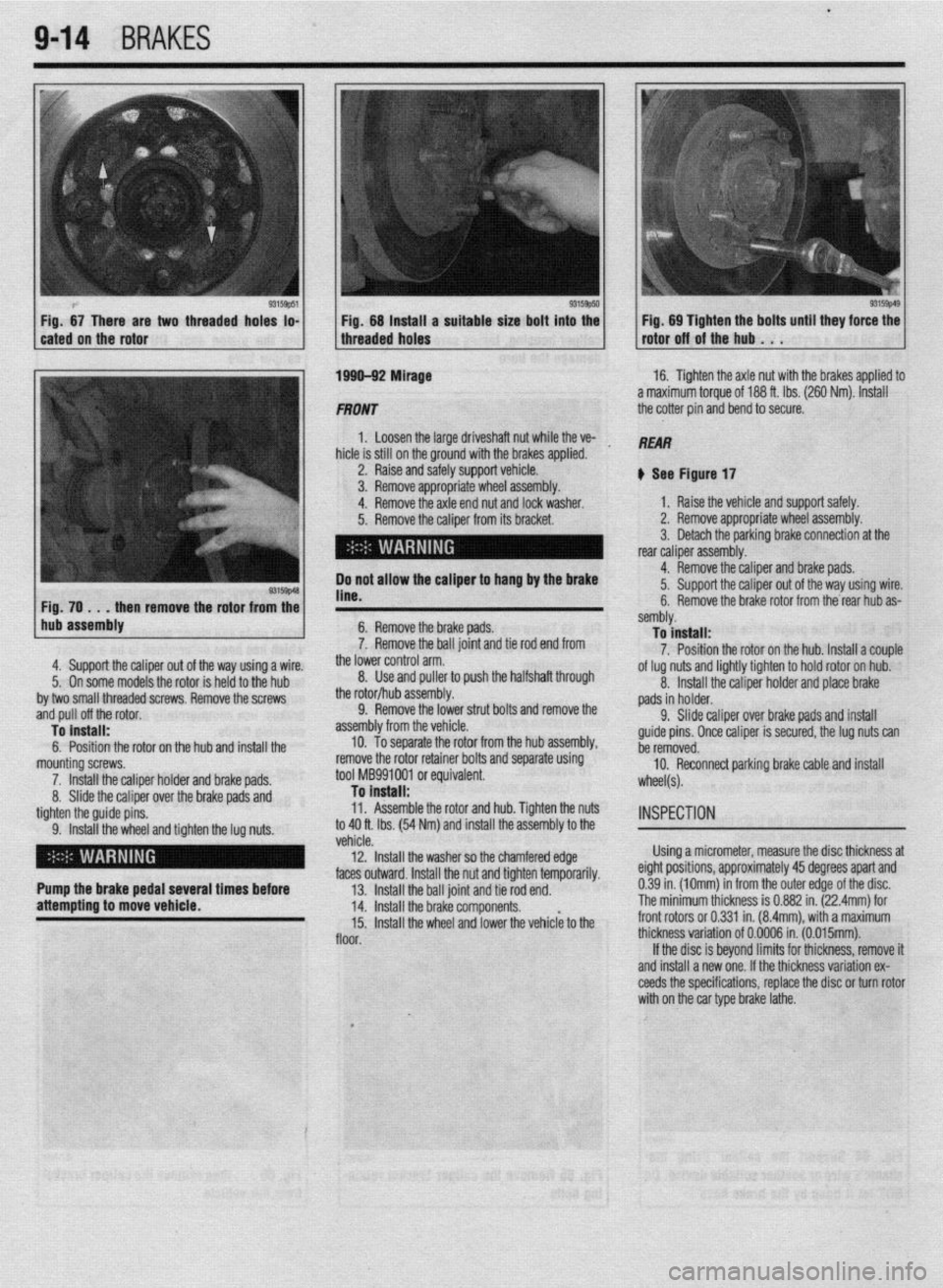
two threaded hoks to- Fig. 68 tnstatt a suitable size bolt into the Fig. 69 Tighten the bolts until they force the
threaded holes rotor off of the hub . . .
1 hub assembly
4. Support the caliper out o
5. On some models the rote
by two small threaded screws. Remove the screws
.mrl n,,ll nff thn rntnr
6. Remove the brake pads.
7. Remove the ball joint and tie rod end from
., 3
me lower control arm.
8. Use and puller to push the halfshaft through f the way using a wire.
)r is held to the hub
ml” p”” “II crw l”L”l. To install:
6. Position the rotor on the hub and install the
mounting screws.
7. Install the caliper holder and brake pads.
8. Slide the caliper over the brake pads and
tighten the guide pins.
9. Install the wheel and tighten the lug nuts. the rotor/hub assembly.
9. Remove the lower strut bolts and remove the
bly from the vehicle.
To separate the rotor from the hub assembly,
sallluly. To install:
7. Position the rotor on the hub. Install a couple
of lug nuts and lightly tighten to hold rotor on hub.
asseml
10.
remove the rotor retainer bolts and separate using
tool MB991001 or equivalent.
To Install:
11. Assemble the rotor and hub. Tighten the nuts
to 40 ft. Ibs. (54 Nm) and install the assembly to the 8. Install the caliper holder and place brake
pads in holder.
9. Slide caliper over brake paAl- --,I inr+*.rli
guide pins. Once caliper is secure1
ho
mmnmrl
I”> a, I” II 13m11
YI, the lug nuts can
U” IUIII”“““.
10. Reconnect parking brake cable and install
wheel(s).
INSPECTION
venae.
12. Install the washer so the chamfered edge Using a micrometer, measure the disc thickness at
.I LL- *.* 1 I
faces outward. Install the nut and tighten temporarily. eignr posmons, approxlmarely
43 aegrees apan ana
Pump the brake pedal several times before
13. Install the ball joint and tie rod end. 0.39 in. (10mm) in from the outer edge of the disc.
attempting to move vehicle.
14. Install the brake components. The minimum thickness is 0.882 in. (22.4mm) for
15. Install the wheel and lower the vehiclk to the front rotors or 0.331 in. (8.4mm), with a maximum
floor. thickness variation of 0.0006 in. (0.015mm).
If the disc is beyond limits for thickness, remove it
and install a new one. If the thickness variation ex-
ceeds the specifications, replace the disc or turn rotor
with on the car type brake lathe.
I
_,
Page 353 of 408
,BRAKiS 9-17
*When servicing drum brakes, only dissem-
ble and assemble one side at a time, leaving
the remaining side intact for reference.
3. Replace the shoe and lininq assembly is any 1. Raise vehicle and support safely.
2. Remove the tire and wheel assembly.
*Note the location of all springs and clips
for proper reassembly.
located is less than the limit. Wh&ever theshoe and
lining assembly is replaced, be sure to replace the
left and right side assemblies as a set to prevent the
car from pulling to one side when braking.
4. If there is a big difference between the thick-
ness of the shoe and lining assembly on the left and
right sides, check the sliding condition of the wheel
cylinder piston. 3. Remove the brake drum.
4. Remove the front shoe-to-rear shoe spring.
5. Remove the shoe-to-lever spring and remove
the adjuster assembly.
6. Remove the shoe hold-down clips and the
brake shoes.
7. Disconnect the parking brake cable from the
m-r ehnnc hu .rnmoAinn t$e horseshoe clip apa&
REMOVAL &INSTALLATION
1990-92 Mirage
ti See Figure 71 To install:
8. Thoroughly clean and dry the backing plate.
Ensure the backing plate bosses are smooth, so
shoes won’t bind.
9. Lubricate backing plate bosses, anchor pin,
and parking brake actuating mechanism with a
lithium-based grease.
10. Remove, clean and dry all remaining parts.
Apply anti-seize to the star wheel threads and transfer
commercially available brakeileaning flu- Brake shoes contain asbestos, which has
been determined to be a cancer causing
ids. agent. Never clean the brake surfaces with
compressed air! Avoid inhaling any dust from
brake surfaces! When cleanina brakes. use all parts to the new shoes.
moved. 11.
13. Connect the parking brake arm to the appro-
Preadjust the shoes so the drum slides on
with a light drag and install brake drum. priate brake shoe.
14. Install a new wheel bearinq self-lockinq nut
a 12. Attach shoes to the backing plate and install
all remaining hardware in the reverse order it was re-
nd torque to 130 ft. Ibs. (180 Nmj. -
15. Install the wheel bearing dust cap and adjust
ie rear brake shoes.
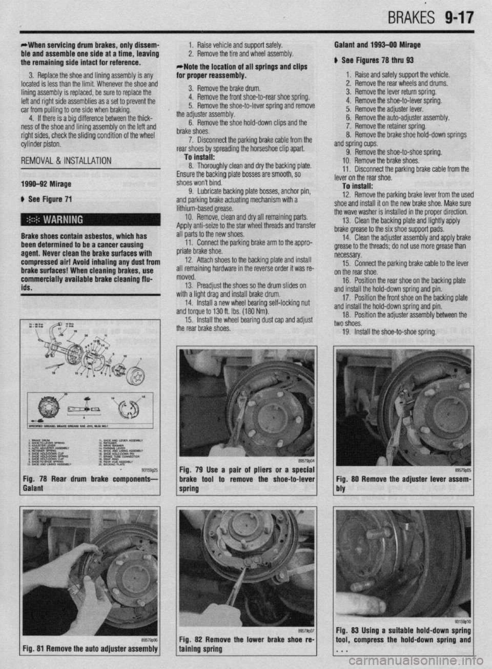
Fig. 81 Remove the auto adjuster assembly 1
89579pc4
8 Rear drum brake components- Fig. 79 Use a pair of pliers or a special
brake tool to remove the shoe-to-lever
spring
Fig. 82 Remove the lower brake shoe re-
taining spring
,
Galant and 1993-00 Mirage
I See Figures 78 thru 93
1. Raise and safely support the vehicle.
2. Remove the rear wheels and drums.
3. Remove the lever return spring.
4. Remove the shoe-to-lever spring.
5. Remove the adjuster lever.
6. Remove the auto-adjuster assembly.
7. Remove the retainer spring.
8. Remove the brake shoe hold-down springs
Bnd spring cups.
9. Remove the shoe-to-shoe spring.
10. Remove the brake shoes.
11. Disconnect the parking brake cable from the
ever on the rear shoe.
To install:
12. Remove the parking brake lever from the use1
shoe and install it on the new brake shoe. Make sure
he wave washer is installed in the proper direction.
13. Clean the backing plate and lightly apply
Irake grease to the six shoe support pads.
14. Clean the adjuster assembly and apply brake
grease to the threads; do not use more grease than
iecessary.
15. Connect the parking brake cable to the lever
In the rear shoe.
16. Position the rear shoe on the backing plate
nd install the hold-down spring and pin.
17. Position the front shoe on the backing plate
ind install the hold-down spring and pin.
18. Position the adjuster assembly between the
wo shoes.
19. Install the shoe-to-shoe spring.
89579po5 Fig. 80 Remove the adjuster lever assem-
bly
93155Qlcl Fig. 83 Using a suitable hold-down spring
tool, compress the hold-down spring and