1900 MITSUBISHI DIAMANTE brake light
[x] Cancel search: brake lightPage 234 of 408
CHASSIS ELECTRICAL 6-31
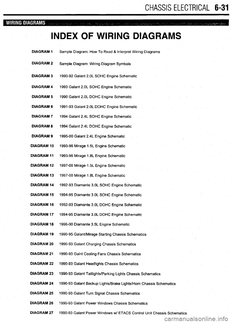
INDEX OF WIRING DIAGRAMS
DIAGRAM 1 Sample Diagram: How To Read & Interpret Wiring Diagrams
DIAGRAM 2
Sample Diagram: Wiring Diagram Symbols
DIAGRAM 3 1990-92 Galant 2.OL SOHC Engine Schematic
DIAGRAM 4 1993 Galant 2.OL SOHC Engine Schematic
DIAGRAM 5 1990 Galant 2.OL DOHC Engine Schematic
DIAGRAM 6 1991-93 Galant 2.OL DOHC Engine Schematic
DIAGRAM 7 1994 Galant 2.4L SOHC Engine Schematic
DIAGRAM 8 1994 Galant 2.4L DOHC Engine Schematic
DIAGRAM 9
199500 Galant 2.4L Engine Schematic
DIAGRAM 10 1993-96 Mirage 1.5L Engine Schematic
DIAGRAM 11 1993-96 Mirage 1.8L Engine Schematic
DIAGRAM 12 1997-00 Mirage 1.5L Engine Schematic
DIAGRAM 13 1997-00 Mirage 1.8L Engine Schematic
DIAGRAM 14 1992-93 Diamante 3.OL SOHC Engine Schematic
DIAGRAM 15 1994-95 Diamante 3.OL SOHC Engine Schematic
DIAGRAM 16 1992-93 Diamante 3.OL DOHC Engine Schematic
DIAGRAM 17 1994-95 Diamante 3.OL DOHC Engine Schematic
DIAGRAM 18 1996-00 Diamante 35L Engine Schematic
DIAGRAM 19 1990-95 Galant/Mirage Starting Chassis Schematics
DIAGRAM 20 1990-93 Galant Charging Chassis Schematics
DIAGRAM 21 1990-93 Galnt Cooling Fans Chassis Schematics
DIAGRAM 22 1990-93 Galant Headlights Chassis Schematics
DIAGRAM 23 1990-93 Galant Taillights/Parking Lights Chassis Schematics
DIAGRAM 24 1990-93 Galant Backup Lights/Brake Lights/Horn Chassis Schematics
DIAGRAM 25 1990-93 Galant Turn Signal Chassis Schematics
DIAGRAM 26 1990-93 Galant Power Windows Chassis Schematics
DIAGRAM 27 1990-93 Galant Power Windows wl ETACS Control Unit Chassis Schematics
Page 235 of 408
6-32 CHASSIS ELECTRICAL
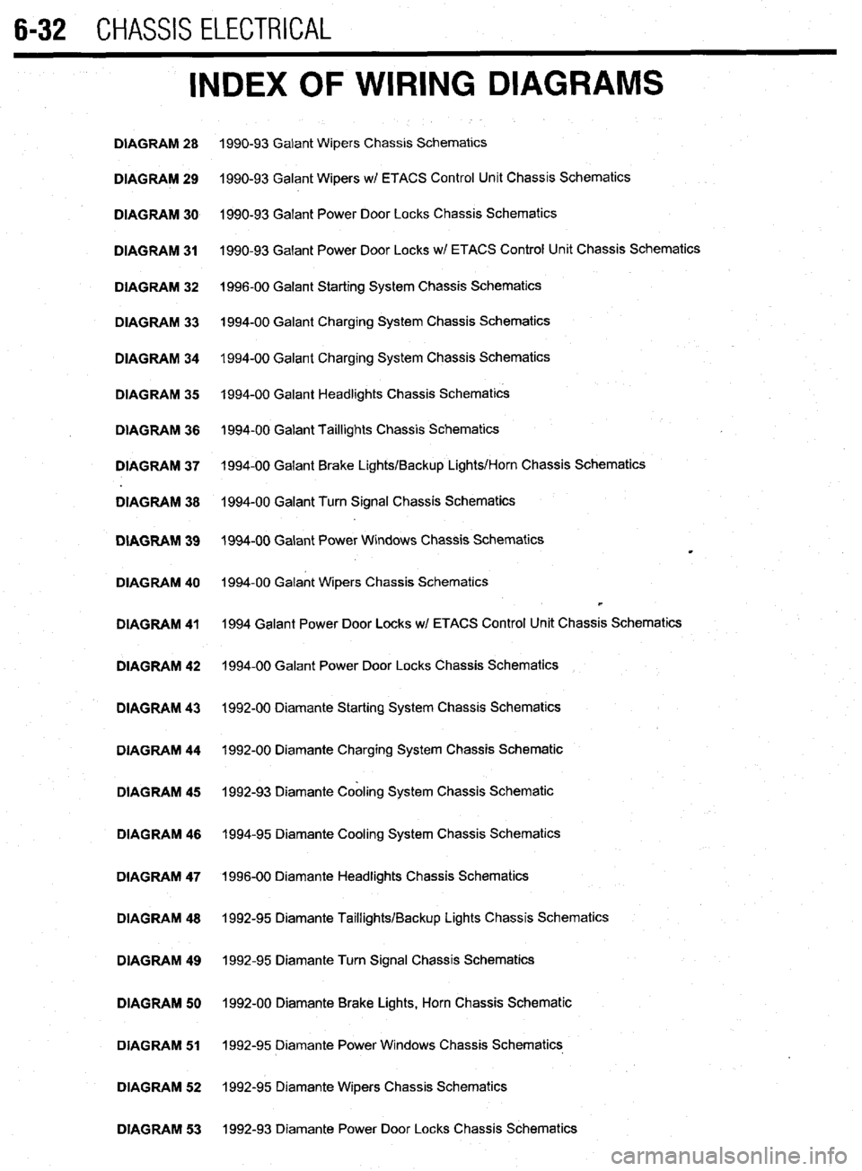
INDEX OF WIRING DIAGRAMS
DIAGRAM 28 1990-93 Galant Wipers Chassis Schematics
DIAGRAM 29 1990-93 Galant Wipers w/ ETACS Control Unit Chassis Schematics
DIAGRAM 30 1990-93 Galant Power Door Locks Chassis Schematics
DIAGRAM 31 1990-93 Galant Power Door Locks wl ETACS Control Unit Chassis Schematics
DIAGRAM 32 1996-00 Galant Starting System Chassis Schematics
DIAGRAM 33 1994-00 Galant Charging System Chassis Schematics
DIAGRAM 34 1994-00 Galant Charging System Chassis Schematics
DIAGRAM 35 1994-00 Galant Headlights Chassis Schematics
DIAGRAM 36 1994-00 Galant Taillights Chassis Schematics
DIAGRAM 37 1994-00 Galant Brake Lights/Backup Lights/Horn Chassis Schematics
DIAGRAM 38 1994-00 Galant Turn Signal Chassis Schematics
DIAGRAM 39 1994-00 Galant Power Windows Chassis Schematics
m
DIAGRAM 40 1994-00 Galant Wipers Chassis Schematics
b
DIAGRAM 41 1994 Galant Power Door Locks w/ ETACS Control Unit Chassis Schematics
DIAGRAM 42 1994-00 Galant Power Door Locks Chassis Schematics
DIAGRAM 43 1992-00 Diamante Starting System Chassis Schematics
DIAGRAM 44 1992-00 Diamante Charging System Chassis Schematic
DIAGRAM 45 1992-93 Diamante Cabling System Chassis Schematic
DIAGRAM 46 1994-95 Diamante Cooling System Chassis Schematics
DIAGRAM 47 1996-00 Diamante Headlights Chassis Schematics
DIAGRAM 48 1992-95 Diamante Taillights/Backup Lights Chassis Schematics
DIAGRAM 49 1992-95 Diamante Turn Signal Chassis Schematics
DIAGRAM 50 1992-00 Diamante Brake Lights, Horn Chassis Schematic
DIAGRAM 51 1992-95 Diamante Power Windows Chassis Schematics
DIAGRAM 52 1992-95 Diamante Wipers Chassis Schematics
DIAGRAM 53 1992-93 Diamante Power Door Locks Chassis Schematics
Page 236 of 408
CHASSIS ELECTRlCiL 6-33
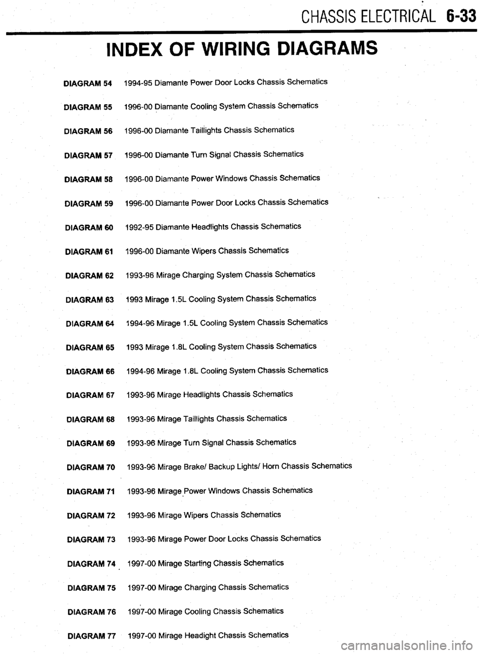
INDEX OF WIRING DIAGRAMS
DIAGRAM 54
DIAGRAM 55
DIAGRAM 56
DIAGRAM 57
DIAGRAM 58
DIAGRAM 59
DIAGRAM 60
DIAGRAM 61
DIAGRAM 62
DIAGRAM 63
DIAGRAM 64
DIAGRAM 65
DIAGRAM 66
DIAGRAM 67
DIAGRAM 68
DIAGRAM 69
DIAGRAM 70
DIAGRAM 71
DIAGRAM 72
DIAGRAM 73
DIAGRAM 74
DIAGRAM 75
DIAGRAM 76
DIAGRAM 77 1994-95 Diamante Power Door Locks Chassis Schematics
1996-00 Diamante Cooling System Chassis Schematics
1996-00 Diamante Taillights Chassis Schematics
1996-00 Diamante Turn Signal Chassis Schematics
1996-00 Diamante Power Windows Chassis Schematics
1996-00 Diamante Power Door Locks Chassis Schematics
1992-95 Diamante Headlights Chassis Schematics
1996-00 Diamante Wipers Chassis Schematics
1993-96 Mirage Charging System Chassis Schematics
1993 Mirage 1.5L Cooling System Chassis Schematics
1994-96 Mirage 1.5L Cooling System Chassis Schematics
1993 Mirage 1.8L Cooling System Chassis Schematics
1994-96 Mirage 1.8L Cooling System Chassis Schematics
1993-96 Mirage Headlights Chassis Schematics
1993-96 Mirage Taillights Chassis Schematics
1993-96 Mirage Turn Signal Chassis Schematics
1993-96 Mirage Brake/ Backup Lights/ Horn Chassis Schematics
1993-98 Mirage-Power Windows Chassis Schematics
1993-96 Mirage Wipers Chassis Schematics
1993-96 Mirage Power Door Locks Chassis Schematics
1997-00 Mirage Starting Chassis Schematics
1997-00 Mirage Charging Chassis Schematics
1997-00 Mirage Cooling Chassis Schematics
1997-00 Mirage Headight Chassis Schematics
Page 237 of 408
6-34 CHASSIS ELECTRICAL
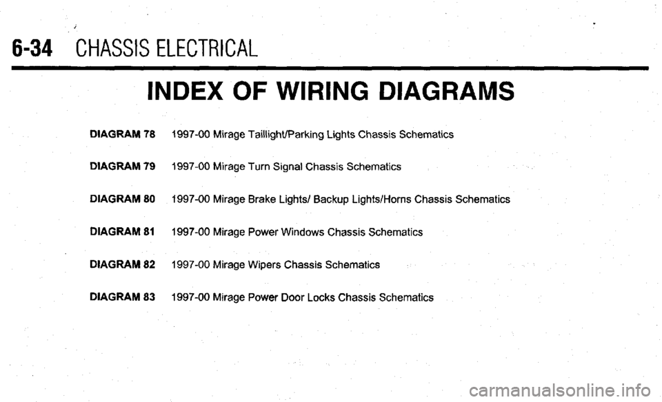
INDEX OF WIRING DIAGRAMS
DIAGRAM 78 1997-00 Mirage Taillight/Parking Lights Chassis Schematics
DIAGRAM 79
1997-00 Mirage Turn Signal Chassis Schematics
DIAGRAM 80 1997-00 Mirage Brake Lights/ Backup Lights/Horns Chassis Schematics
DIAGRAM 81
1997-00 Mirage Power Windows Chassis Schematics
DIAGRAM 82 1997-00 Mirage Wipers Chassis Schematics
DIAGRAM 83 1997-00 Mirage Power Door Locks Chassis Schematics
Page 249 of 408
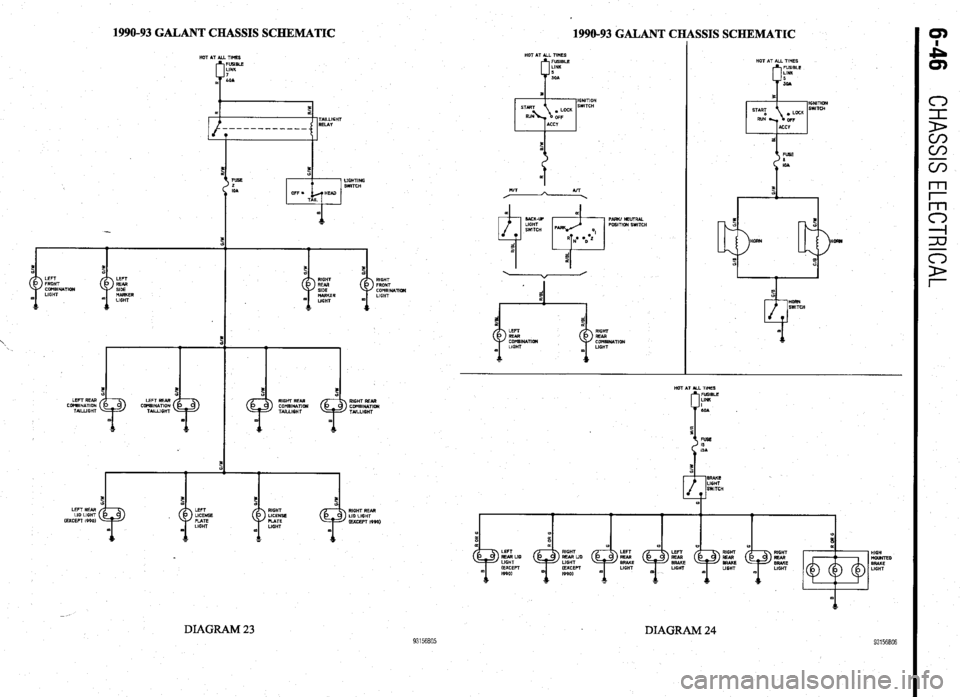
1990-93 GALANT CHASSIS SCHEMATIC
1990-93 GALANT CHASSIS SCHEMATIC
HOT AT ALL TINES
FUSIBLE
LINK
I
LOA
FUSE
LIGHTING
2
SWITCH
IOA
LEFT REAR
LID LIGHT
(EXCEPT 19901 RIGHT
FRONT
coMBINATla4
LIGHT
n -
HOT AT ALL TIMES
P FUSIBLE
LINK
5
JOA
PARK/ NEUTRAL
PQSITION SWITCH
RIGHT
REAR
COnSlNATloN
LIGHT
5
+ RIGHT REAR
COHSINATION
TAlLLIGHT
ID
RIGHT REAR
LID LIGHT
EXCEPT 1999) HOT AT ALL TIMES
FUSIBLE
LINK
LA
B
IGNITION
SWITCH
ACCY
d
FUS2
5
lo*
5
- t
m
;
e
”
l
L
(D
+
HIGH
WOWED
BRAKE
LIGHT
DIAGRAM 23
DIAGRAM 24 93156B05
93156806
Page 272 of 408
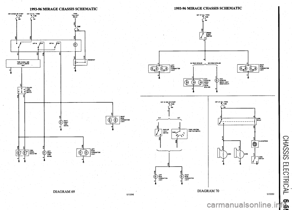
1993-96 MIRAGE CHASSIS SCHEMATIC 1993-96 MIRAGE CHASSIS SCHEMATIC
TURN SIGNAL AND
HAZARD FIASHER
WIT -
COLIJNN
TWN
SIGNAL
SWITCH OFF. 0
c
LEFT
REAR
CDMSINA
LIGHT
HIGH
NOWTED
BRAKE LIGHT
RBAR SHELF)
HOT IN Ruw OR START
FUSE
e
IQ*
> MGWT
FRONT
2LL
SIGNAL LEFT
REAR
COtlBINATlDN
LIGHT
DIAGRAM 69
RIGHT
Zh~T10t4
LIGHT
PARK/ NEUTRAL
POSITION SWITCH RIGHT
REAR
COtlBIKATlQN
UGHT
HOT AT Ml. TIMES
RIGHT
REAR
COHSINATION
LIGHT
DIAGRAM 70 93156850
CI)
72
D
cn
m
cn
Page 289 of 408
7-10 DRIVETRAIN
The automatic transaxle allows engine torque and
power to be transmitted to the front wheels within a
narrow range of engine operating speeds. It will allow
the engine to turn fast enough to produce plenty of
power and torque at very low speeds, while keeping it
at a sensible rpm at high vehicle speeds (and it does
this job without driver assistance). The transaxle uses
a light fluid as the medium for the transmission of
power. This fluid also works in ths operation of vari-
ous hydraulic control circuits and as a lubricant. Be-
cause the transaxle fluid performs all of these func-
tions, trouble within the unit can easily travel from one
part to another For this reason, and because of the
complexity and unusual operating principles of the
transaxle, a very sound understanding of the basic
principles of operation will simplify troubleshooting
REMOVAL &INSTALLATION
Pan removal, fluid and filter
in Section 1 of this manual changes are covered
REMOVAL &INSTALLATION
1990-97 Mirage and 1990-93 Galant
# See Figure 44
1. Disconnect the negative battery cable.
2. Disconnect the selector cable from the lever
3. Remove the two retaining screws and lift off
the switch.
To install: 4. Mount and position new switch. Do not tighten
the bolts until the switch is adjusted.
5. Connect selector cable and adjust switch.
6. After installation and adjustment make sure the
engine only starts in the
P and N selections. Also check
that the reverse lights operate only in the R selectlon.
1994-00 Galant and 1998-00 Mirage
e See Figure 44
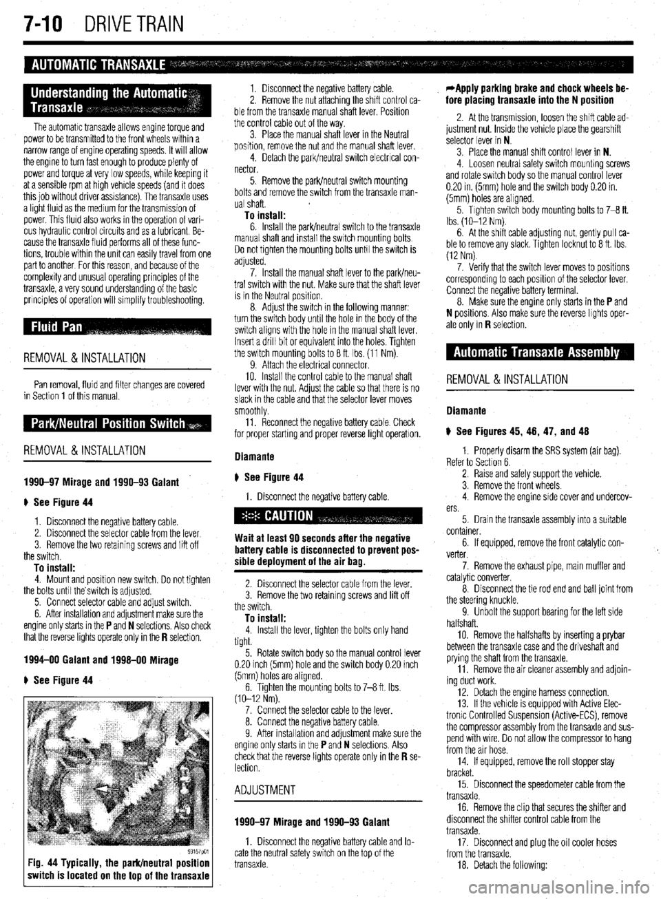
93157pm Fig. 44 Typically, the park/neutral position
switch is located on the top of the transaxle
1. Disconnect the negative battery cable.
2. Remove the nut attaching the shift control ca-
ble from the transaxle manual shaft lever. Position
the control cable out of the way.
3. Place the manual shaft lever in the Neutral
position, remove the nut and the manual shaft lever.
4. Detach the park/neutral switch electrical con-
nector.
5. Remove the park/neutral switch mounting
bolts and remove the switch from the transaxle man-
ual shaft.
To install: 6. Install the park/neutral switch to the transaxle
manual shaft and install the switch mounting bolts
Do not tighten the mounting bolts unh the switch is
adjusted.
7. Install the manual shaft lever to the park/neu-
tral switch with the nut. Make sure that the shaft lever
is in the Neutral position.
8. Adjust the switch in the following manner:
turn the switch body until the hole in the body of the
switch aligns with the hole in the manual shaft lever.
Insert a drill bit or equivalent into the holes. Tighten
the switch mounting bolts to 8 ft. Ibs. (11 Nm).
9. Attach the electrical connector.
10. Install the control cable to the manual shaft
lever with the nut. Adjust the cable so that there is no
slack in the cable and that the selector lever moves
smoothly
11. Reconnect the negative battery cable Check
for proper starting and proper reverse light operatron.
Diamante
ti See Figure 44
1. Disconnect the negative battery cable.
Wait at least 90 seconds after the negative
battery cable is disconnected to prevent pos-
sible deployment of the air bag.
2. Disconnect the selector cable from the lever.
3. Remove the two retaining screws and lift off
the switch.
To install: 4. Install the lever, tighten the bolts only hand
tight.
5. Rotate switch body so the manual control lever
0.20 inch (5mm) hole and the switch body 0.20 inch
(5mm) holes are aligned.
6. Tighten the mounting bolts to 7-8 ft. Ibs.
(10-12 Nm).
7. Connect the selector cable to the lever.
8. Connect the negative battery cable.
9. After installahon and adjustment make sure the
engine only starts in the
P and N selections. Also
check that the reverse lights operate only in the R se- lection.
ADJUSTMENT
1990-97 Mirage and 1990-93 Galant
1. Disconnect the negative battery cable and lo-
cate the neutral safety switch on the top of the
transaxle.
*Apply parking brake and chock wheels be-
fore placing transaxle into the N position
2. At the transmission, loosen the shift cable ad-
justment nut. Inside the vehicle place the gearshift
selector lever in N
3. Place the manual shift control lever in N.
4. Loosen neutral safety switch mounhng screws
and rotate switch body so the manual control lever
0.20 in. (5mm) hole and the switch body 0.20 in.
(5mm) holes are aligned.
5. Tighten switch body mounting bolts to 7-8 ft.
Ibs. (lo-12 Nm).
6. At the shift cable adjusting nut, gently pull ca-
ble to remove any slack. Tighten locknut to 8 ft. Ibs.
(12 Nm)
7. Verify that the switch lever moves to positions
corresponding to each position of the selector lever.
Connect the negative battery terminal.
8. Make sure the engine only starts in the
P and
N positions. Also make sure the reverse lights oper-
ate only in
R selection.
REMOVAL&INSTALLATION
Diamante
) See Figures 45, 46, 47, and 48
1. Properly disarm the SRS system (air bag).
Refer to Section 6.
2. Raise and safely support the vehicle.
3. Remove the front wheels.
4. Remove the engine side cover and undercov-
ers.
5. Drain the transaxle assembly into a suitable
container.
6. If equipped, remove the front catalytic con-
verter.
7. Remove the exhaust pipe, main muffler and
catalytic converter.
8. Disconnect the tie rod end and ball joint from
the steering knuckle.
9. Unbolt the support bearing for the left side
halfshaft.
10. Remove the halfshafts by inserting a prybar
between the transaxle case and the driveshaft and
prying the shaft from the transaxle.
11. Remove the air cleaner assembly and adjoin-
ing duct work.
12. Detach the engine harness connection.
13. If the vehicle is equipped with Active Elec-
tronlc Controlled Suspension (Active-ECS), remove
the compressor assembly from the transaxle and sus-
pend with wire. Do not allow the compressor to hang
from the air hose.
14. If equipped, remove the roll stopper stay
bracket.
15. Disconnect the speedometer cable from the
transaxle.
16. Remove the clip that secures the shifter and
disconnect the shifter control cable from the
transaxle.
17. Disconnect and plug the oil cooler hoses
from the transaxle.
18. Detach the following:
Page 292 of 408
DRIVETRAIN 7-13
27. Shde the transaxle rearward and carefully
lower it from the vehicle.
To install: 28. After the torque converter has been mounted
on the transaxle, install the transaxle assembly to the
engine. Install the mounting bolts and tighten to 35
ft. Ibs. (48 Nm).
29. Install the transaxle lower coupling bolt and
tighten to 21-25 ft Ibs. (29-34 Nm).
30. Connect the torque converter to the flexplate
and tighten the bolts to 33-38 ft. Ibs. (45-52 Nm).
31. Install the cover to the transaxle bellhous-
ing and tighten the mounting bolts to 7 ft. Ibs. (9
Nm).
32 Install the crossmember and tighten the front
mounting bolts to 65 ft. Ibs (88 Nm) and the rear
bolt to 54 ft. Ibs. (73 Nm) Install the front engine roll
stopper through-bolt and lightly tighten. Once the full
weight of the engine is on the mounts, tighten the ’
bolt to 42 ft. Ibs. (57 Nm),
33. Install the triangular stay bracket and tighten
the mounting bolts to 65 ft. Ibs. (88 Nm).
34. Install the halfshafts, using new circlips on
the axle ends.
When installing the axleshaft, keep the in-
board joint straight in relation to the axle, so
as not to damage the oil seal lip of the
transaxle with the serrated part of the half-
shaft.
35. Connect the tie rod and ball joints to the
steering knuckle. Tighten the ball joint self-locking
nuts to 48 ft. Ibs. (65 Nm). Tighten the tie rod end nut
to 21 ft. Ibs. (28 Nm) and secure with a new cotter
pin.
36. Connect the damper fork to the lower control
arm and tighten the through-bolt to 65 ft Ibs. (88
Nm).
37. Connect the stabilizer link to the damper fork,
and tighten the self-locking nut to 29 ft. Ibs. (39 Nm).
38. Install the undercover.
39. Install the wheels and carefully lower the ve-
hicle
40. Install the transaxle mount bracket to the
transaxle, and tighten the mounting nuts to 32 ft. Ibs.
(43 Nm).
41. Install the rear roll stopper mounting bracket.
42. Remove the engine support. Tighten the
transaxle mount through-bolt to 51 ft. Ibs. (69 Nm)
and tighten the front engine roll stopper through-bolt.
43. Install the upper transaxle mounting bolts
and tighten to 35 fl. Ibs. (48 Nm).
44. Install the starter motor.
45. Install the dipstick tube and the dipstick
46. Install the shifter cable mounting bracket.
47. Connect the shifter lever and tighten the re-
taining nut to 14 ft. Ibs. (19 Nm).
48. Connect the oil cooler lines and secure with
clamps.
49. Attach the electrical connectors for the
speedometer, solenoid, neutral safety switch (in-,
hibitor switch), the pulse generator, kickdown servo
switch and oil temperature sensor.
50. Install the air cleaner and the air intake hose.
51. Connect the negative battery cable.
52. Make sure the vehicle is level, and refill the
transaxle. Start the engine and allow to idle for 2 minutes. Apply parking brake and move selector
through each gear position, ending in N. Recheck
fluid level and add if necessary. Fluid level should be
between the marks in the HOT range.
53. Check the transaxle for proper operation.
Make sure the reverse lights come on when in re-
verse and the engine starts only in
P or N.
Mirage
*If the vehicle is going to be rolled on its
wheels while the halfshafts are out of the ve-
hicle, obtain two outer CV-joints or proper
equivalent tools and install to the hubs. If the
vehicle is rolled without the proper torque
applied to the front wheel bearings, the bear-
ings will no longer be usable.
1. Disconnect the negative battery cable then
the positive battery cable.
2. Remove the battery and battery tray.
3. Remove the air hose and air cleaner assem-
bly.
4. Raise the vehicle and support safely.
5. Remove the under guard pan.
6. Drain the transaxle oil into a suitable con-
tainer.
7. If equipped with 1.6L engine, remove the ten-
sion rod.
8. Disconnect the control cable and cooler
lines.
9. On 3-speed transaxles, disconnect the throt-
tle control cable.
10. On 4-speed transaxles, perform the following:
a. Detach the shift control solenoid valve
connector.
b. Disconnect the inhibitor switch and kick-
down servo switch.
c. Disconnect the pulse generator and oil
temperature sensor.
11. Disconnect the speedometer cable and re-
move the starter.
12. Remove the transaxle mounting bolts and
bracket.
13. Disconnect the stabilizer bar from the lower
control arm.
14. Disconnect the steering tie rod end and the
ball joint from the steering arm.
15. Remove the halfshafts at the inboard side
from the transaxle. Tie the joint assembly aside.
*It is not necessary to disconnect the half-
shafts from the wheel hubs.
16. Support the engine and remove the center
member.
17. Remove the bellhousing cover and remove
the driveplate bolts.
18 Remove the transaxle assembly lower con-
necting bolt, located just over the halfshaft opening.
19. Properly support the transaxle assembly, then
lower it, moving it to the right for clearance.
To install: 20. After the torque converter has been mounted
on the transaxle, install the transaxle assembly on the
engine. Install the mounting bolts and tighten to
31-40 ft. Ibs. (43-55 Nm) on 1990-92 models and
35 ft. Ibs. (48 Nm) on 1993-00 models.
21. Tighten the driveplate bolts to 33-38 ft. Ibs.
(46-53 Nm). Install the bellhousing cover.
22. Install the center member. 23. Replace the circlips and install the halfshafts
to the transaxle.
24. Install the tie rods, ball joints and stabilizer
links to the steering arm
25. Install the transaxle mounting bracket and
bolts.
26. Install the starter.
27. Connect the speedometer cable.
28. Connect the inhibitor switch, kickdown servo
switch, the pulse generator and oil temperature sen-
sor, if disconnected.
29. Connect the shift control solenoid valve con-
nector.
30. Connect the control cables and oil cooler
lines.
31. Install the tension rod, if removed.
32. Install the air cleaner assembly.
33. Install the battery tray and battery.
34. Connect the positive then the negative termi-
nal.
35. Refill with Dexron@ II, Mopar ATF Plus type
7176 or equivalent, automatic transaxle fluid.
36. Start the engine and allow to idle for two min-
utes. Apply parking brake and move selector through
each gear position, ending in N. Recheck fluid level
and add if necessary. Fluid level should be between
the marks in the HOT range.
ADJUSTMENTS
Shifter Control Cable Adjustment
1. The shifter cable adjustment is done at the
neutral safety switch (inhibitor switch). Locate the
switch on the transaxle and note the alignment holes
in the arm and the body of the switch. Place the se-
lector lever in N. Place the manual lever of the
transaxle in the neutral position.
2. Check alignment of the hole in the manual
control lever to the hole in the inhibitor switch body.
If the holes do not align, adjustment is required.
3. To adjust, loosen the nut on the cable end and
pull the cable end by hand until the alignment holes
match. Tighten the nut. Check that the transaxle
shifts and conforms to the positions of the selector
lever.
Throttle Valve Cable
The throttle valve adjustment applies only to the
1990-96 Mirage.
1. Place selector lever and manual control lever
in N position.
2. Loosen adjusting nut. While lightly pulling on
control cable tighten mounting nut to 7-10 ft. Ibs.
(X-14 Nm).
3. When adjustment is complete, be sure selector
lever is still in the N position. Verify all functions
correspond to the position indicated on the selector
lever.
The halfshaft removal and installation and over-
haul are the same as a manual transaxle Please refer
to Manual Transaxle in this Section