1900 MITSUBISHI DIAMANTE brake light
[x] Cancel search: brake lightPage 356 of 408
‘I
9-20 ,BRAKES
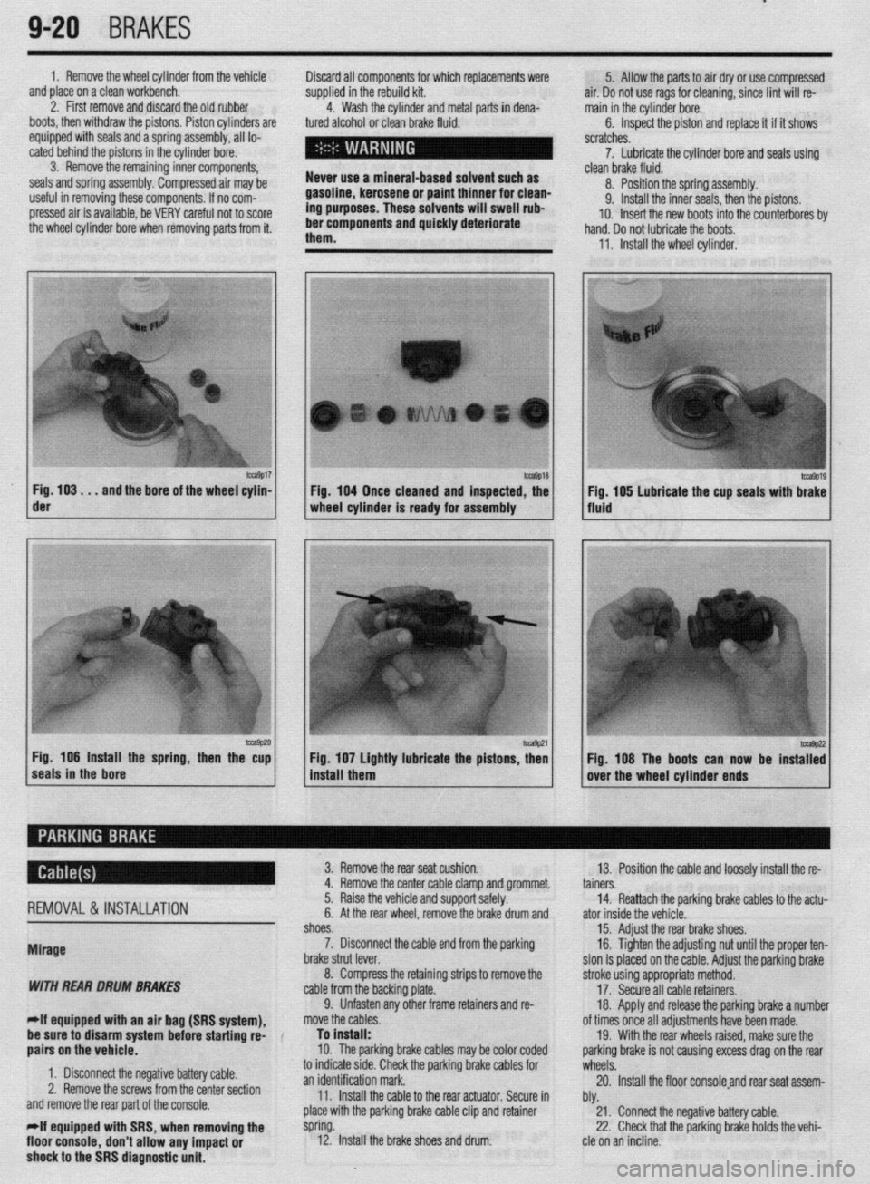
1. Remove the wheel cylinder from the vehicle
and place on a clean workbench.
2. First remove and discard the old rubber
boots, then withdraw the pistons. Piston cylinders are
equipped with seals and a spring assembly, all lo-
cated behind the pistons in the cylinder bore.
3. Remove the remaining inner components,
seals and spring assembly. Compressed air may be
useful in removing these components. If no com-
pressed air is available, be VERY careful not to score
the wheel cylinder bore when removing parts from it. Discard all components for which replacements were
supplied in the rebuild kit.
4. Wash the cylinder and metal parts in dena-
tured alcohol or clean brake fluid.
Never use a mineral-based solvent such as
gasoline, kerosene or paint thinner for clean-
ing purposes. These solvents will swell rub-
ber components and quickly deteriorate
them. 5. Allow the parts to air dry or use compressed
air. Do not use rags for cleaning, since lint will re-
main in the cylinder bore.
6. Inspect the piston and replace it if it shows
scratches.
7. Lubricate the cylinder bore and seals using
- clean brake fluid.
8. Position the spring assembly.
9. Install the inner seals, then the pistons.
IO. Insert the new boots into the counterbores bv
hand. Do not lubricate the boots,
11, Install the wheel cylinder,
m9017 Fig. 103. . .
and the bore of the wheel cylin- der
-9P20 Fig. 106 Install the spring, then the cup
seals in the bore 1 Fig. 104 Once cleaned and inspected, the
1 wheel cylinder Is ready for assembly
1 install them Fig 107 Lightly lubricate the pistons z
’ Fig. 108 The boots can now be instaT:
over the wheel cylinder ends
REMOVAL& INSTALLATION
Mirage
WITH REAR DRUM BRAKES
-If equipped witti an air bag (SRS system), 3. Remove the rear seat cushion.
13. Position the cable and loosely install the re-
4. Remove the center cable clamp and grommet.
tainers.
5. Raise the vehicle and support safely.
14. Reattach the parking brake cables to the actu-
6. At the rear wheel, remove the brake drum and
ator inside the vehicle.
shoes.
15. Adjust the rear brake shoes.
7. Disconnect the cable end from the parking
16. Tighten the adjusting nut until the proper ten-
brake strut lever.
sion is placed on the cable. Adjust the parking brake
8. Compress the retaining strips to remove the
stroke using appropriate method.
cable from the backing plate.
17. Secure all cable retainers,
9. Unfasten any other frame retainers and re-
18. Apply and release the parking brake a number
move the cables.
of times once all adjustments have been made.
be sure to disarm system
befok starting rd-
aairs on the vehicle. To install:
10. The parkinq brake cables mav be color coded 19. With the rear wheels raised, make sure the
oarkino brake is not causina excess draa on the rear
1. Disconnect the negative battery cable.
2. Remove the screws from the center section
and remove the rear part of the console.
*If equipped with SRS, when removing the
floor console,
don’t allow any impact or
shock to the SRS diagnostic unit. to indicate stde. Check the parking brake cables for
wheels: .A
an identification mark.
20. Install the floor consoleand rear seat assem-
11. Install the cable to the rear actuator. Secure in
bly.
place with the parking brake cable clip and retainer
21. Connect the negative battery cable.
spring.
22. Check that the parking brake holds the vehi-
12. Install the brake shoes and drum.
cle on an incline.
Page 359 of 408
BRAKES 9-23
1. Make sure the parking brake cable is free and
is not frozen or sticking.
2. Apply the parking brake with 45 Ibs. (200 N) of
force while counting the number of notches. The de-
sired parking brake stroke should be 5-7 notches.
3. If adjustment is required, access the adjusting
nut from inside the floor console.
4. Loosen the locknut on the cable rod.
5. Rotate the adjusting nut to adjust the parking
brake stroke to the 5-7 notch setting. After making
the adjustment, check there is no looseness between
the adjusting nut and the parking brake lever, then
tighten the locknut.
*Do not adjust the parking brake too tight. If
the number of notches is less than specifica-
tion, the cable has been pulled too much and
the automatic adjuster will fail or the brakes
will drag.
6. After adjusting the lever stroke, raise the rear of
the vehicle and safely support. With the parking brake
lever in the released position, turn the rear wheels to
confirm that the rear brakes are not dragging.
7. Check that the parking brake holds the vehicle
on an incline.
Galant
‘ 1990-93 VEHICLES
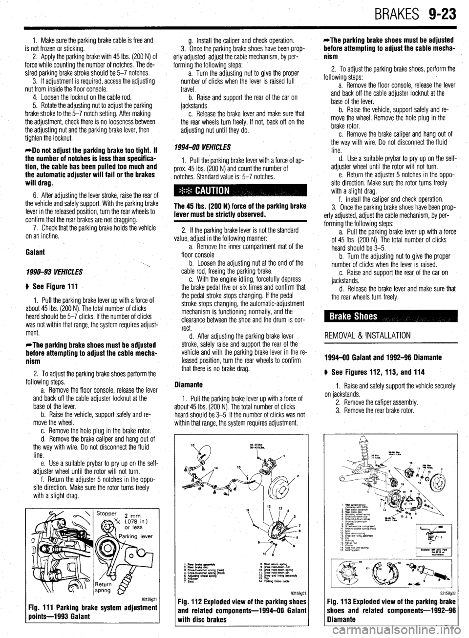
# See Figure 111
1. Pull the parking brake lever up with a force of
about 45 Ibs. (200 N). The total number of clicks
heard should be 5-7 clicks. If the number of clicks
was not within that range, the system requires adjust-
ment.
*The parking brake shoes must be adjusted
before attempting to adjust the cable mecha-
nism
2. To adjust the parking brake shoes perform the
following steps.
a. Remove the floor console, release the lever
and back off the cable adjuster locknut at the
base of the lever.
b. Raise the vehicle, support safely and re-
move the wheel.
c. Remove the hole plug in the brake rotor.
d. Remove the brake caliper and hang out of
the way with wire. Do not disconnect the fluid
line.
e. Use a suitable prybar to pry up on the self-
adjuster wheel until the rotor will not turn.
f. Return the adjuster 5 notches in the oppo-
site direction. Make sure the rotor turns freely
with a slight drag.
Fig. 111 Parking brake system adjustment
points-1993 Galant
g. Install the caliper and check operation.
3. Once the parking brake shoes have been prop-
erly adjusted, adjust the cable mechanism, by per-
forming the following steps: _
a. Turn the adjusting nut to give the proper
number of clicks when the lever is raised full
travel.
b. Raise and support the rear of the car on
jackstands.
c. Release the brake lever and make sure that
the rear wheels turn freely. If not, back off on the
adjusting nut until they do.
1994470 VEHICLES
1, Pull the parking brake lever with a force of ap-
prox. 45 Ibs. (200 N) and count the number of
notches. Standard value is: 5-7 notches.
The 45 lbs. (200 N) force of the parking brake
lever must be strictly observed.
2. If the parking brake lever is not the standard
value, adjust in the following manner:
a. Remove the inner compartment mat of the
floor console
b. Loosen the adjusting nut at the end of the
cable rod, freeing the parking brake.
c. With the engine idling, forcefully depress
the brake pedal five or six times and confirm that
the pedal stroke stops changing. If the pedal
stroke stops changing, the automatic-adjustment
mechanism is functioning normally, and the
clearance between the shoe and the drum is cor-
rect.
d. After adjusting the parking brake lever
stroke, safely raise and support the rear of the
vehicle and with the parking brake lever in the re-
leased position, turn the rear wheels to confirm
that there is no brake drag.
Diamante
1. Pull the parking brake lever up with a force of
about 45 Ibs. (200 N). The total number of clicks
heard should be 3-5. If the number of clicks was not
within that range, the system requires adjustment.
93159901 Fig. 112 Exploded view of the parking shoes
and related components-1994-00 Galant
with disc brakes *The parking brake shoes must be adjusted
before attempting to adjust the cable mecha-
nism
2. To adjust the parking brake shoes, perform the
following steps: -
a. Remove the floor console, release the lever
and back off the cable adjuster locknut at the
base of the lever.
b. Raise the vehicle, support safely and re-
move the wheel. Remove the hole plug in the
brake rotor.
c. Remove the brake caliper and hang out of
the way with wire, Do not disconnect the fluid
line.
d. Use a suitable prybar to pry up on the self-
adjuster wheel until the rotor will not turn.
e. Return the adjuster 5 notches in the oppo-
site direction, Make sure the rotor turns freely
with a slight drag.
f. Install the caliper and check operation.
3. Once the parking brake shoes have been prop-
erly adjusted, adjust the cable mechanism, by per-
forming the following steps:
a. Pull the parking brake lever up with a force
of 45 Ibs. (200 N). The total number of clicks
heard should be 3-5.
b. Turn the adjusting
nut to give the proper
number of clicks when the lever is raised.
c. Raise and support the rear of the car on
jackstands.
d. Release the brake lever and make sure
that the rear wheels turn freely.
REMOVAL &INSTALLATION
1994-00 Galant and 1992-96 Diamante
# See Figures 112, 113, and 114
1. Raise and safely support the vehicle securely
on jackstands.
2. Remove the caliper assembly.
3. Remove the rear brake rotor.
I
I 93159902 Fig. 113 Exploded view of the parking brake
shoes and related components-1992-96
Diamante
Page 360 of 408
9-24 BRAKES
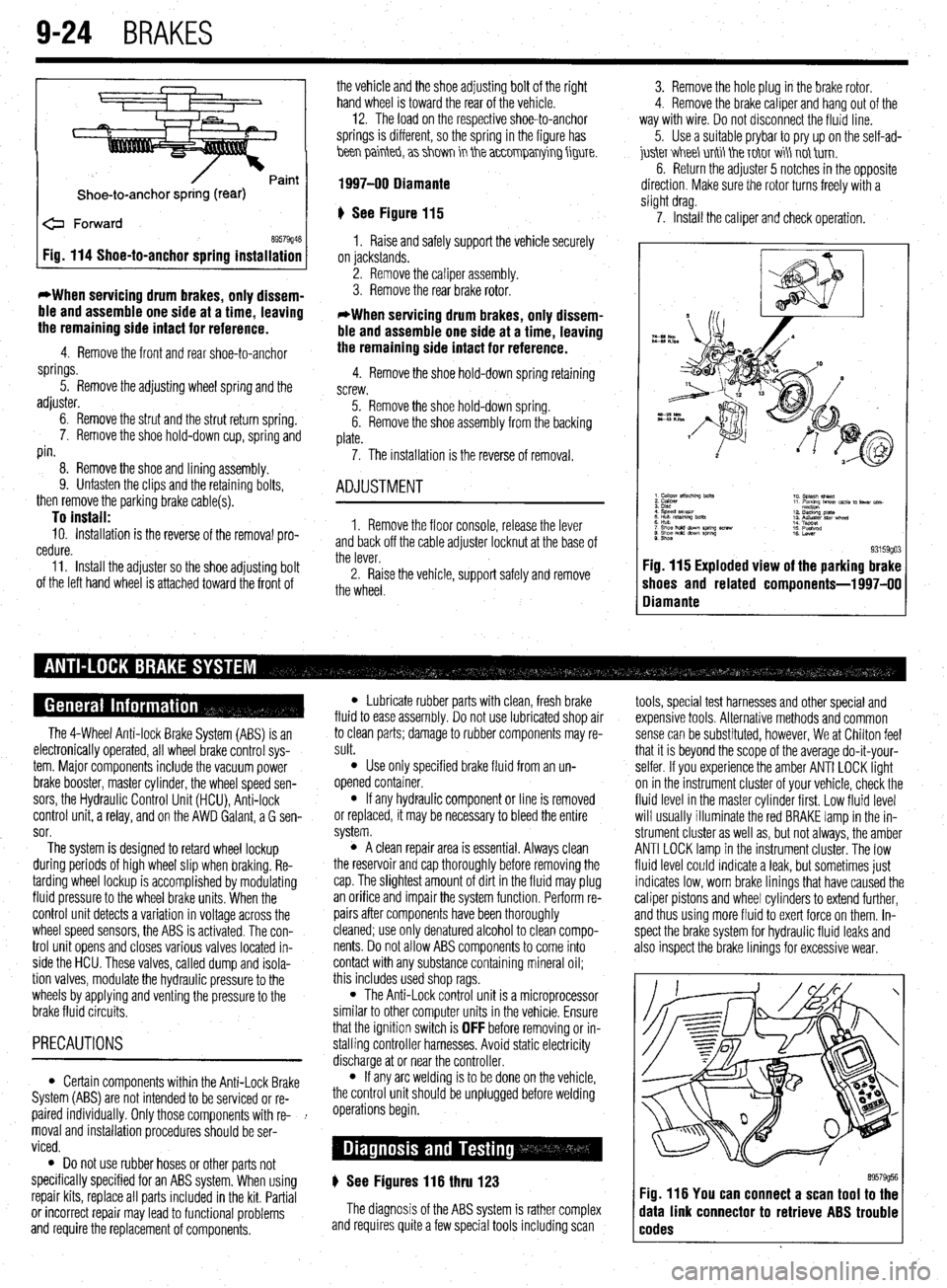
Shoe-to-anchor spring (rear)
e Forward
69579946 Fig. 114 Shoe-to-anchor spring installation
*When servicing drum
brakes, only dissem-
ble and assemble one side at a time, leaving
the remaining side intact for reference.
4. Remove the front and rear shoe-to-anchor
springs.
5. Remove the adjusting wheel spring and the
adjuster.
6. Remove the strut and the strut return spring.
7. Remove the shoe hold-down cup, spring and
pin.
8. Remove the shoe and lining assembly.
9. Unfasten the clips and the retaining bolts,
then remove the parking brake cable(s).
To install: 10. Installation is the reverse of the removal pro-
cedure.
11. Install the adjuster so the shoe adjusting bolt
of the left hand wheel is attached toward the front of the vehicle and the shoe adjusting bolt of the right
hand wheel is toward the rear of the vehicle. -
12. The load on the respective shoe-to-anchor
springs is different, so the spring in the figure has
hen painteb, a> shm in the a~~0mparrying figure.
1997-00 Diamante
‘) See Figure 115
1. Raise and safely support the vehicle securely
on jackstands.
2. Remove the caliper assembly.
3. Remove the rear brake rotor.
*When servicing drum brakes, only dissem-
ble and assemble one side at a time, leaving
the remaining side intact for reference.
4. Remove the shoe hold-down spring retaining
screw.
5. Remove the shoe hold-down spring.
6. Remove the shoe assembly from the backing
plate.
7. The installation is the reverse of removal.
ADJUSTMENT
1. Remove the floor console, release the lever
and back off the cable adjuster locknut at the base of
the lever.
2. Raise the vehicle, support safely and remove
the wheel. 3. Remove the hole plug in the brake rotor.
4. Remove the brake caliper and hang out of the
way with wire. Do not disconnect the fluid line.
5. Use a suitable prybar to pry up on the self-ad-
juskr V&I&I unti tie T&IT wi\ not tirn.
6. Return the adjuster 5 notches in the opposite
direction. Make sure the rotor turns freely with a
slight drag.
7. Install the caliper and check operation.
9. Shoe 93159go3 Fig. 115 Exploded view of the parking brake
shoes and related components-l 997-00
Diamante
The 4-Wheel Anti-lock Brake System (ABS) is an
electronically operated, all wheel brake control sys-
tem. Major components include the vacuum power
brake booster, master cylinder, the wheel speed sen-
sors, the Hydraulic Control Unit (HCU), Anti-lock
control unit, a relay, and on the AWD Galant, a G sen-
sor.
The system is designed to retard wheel lockup
during periods of high wheel slip when braking. Re-
tarding wheel lockup is accomplished by modulating
fluid pressure to the wheel brake units. When the
control unit detects a variation in voltage across the
wheel speed sensors, the ABS is activated. The con-
trol unit opens and closes various valves located in-
side the HCU. These valves, called dump and isola-
tion valves, modulate the hydraulic pressure to the
wheels by applying and venting the pressure to the
brake fluid circuits.
PRECAUTIONS
l Certain components within the Anti-Lock Brake
System (ABS) are not intended to be serviced or re-
paired individually. Only those components with re- !
moval and installation procedures should be ser-
viced.
0 Do not use rubber hoses or other parts not
specifically specified for an ABS system. When using
repair kits, replace all parts included in the kit. Partial
or incorrect repair may lead to functional problems
and require the replacement of components.
l Lubricate rubber parts with clean, fresh brake
fluid to ease assembly. Do not use lubricated shop air
to clean parts; damage to rubber components may re-
sult.
l Use only specified brake fluid from an un-
opened container.
l If any hydraulic component or line is removed
or replaced, it may be necessary to bleed the entire
system.
l A clean repair area is essential. Always clean
the reservoir and cap thoroughly before removing the
cap. The slightest amount of dirt in the fluid may plug
an orifice and impair the system function. Perform re-
pairs after components have been thoroughly
cleaned; use only denatured alcohol to clean compo-
nents. Do not allow ABS components to come into
contact with any substance containing mineral oil;
this includes used shop rags.
l The Anti-Lock control unit is a microprocessor
similar to other computer units in the vehicle. Ensure
that the ignition switch is
OFF before removing or in-
stalling controller harnesses. Avoid static electricity
discharge at or near the controller.
l If any arc welding is to be done on the vehicle,
the control unit should be unplugged before welding
operations begin.
) See Figures 116 thru 123
The diagnosis of the ABS system is rather complex
and requires quite a few special tools including scan tools, special test harnesses and other special and
expensive tools. Alternative methods and common
sense can be substituted, however, We at Chilton feel
that it is beyond the scope of the average do-it-your-
selfer. If you experience the amber ANTI LOCK light
on in the instrument cluster of your vehicle, check the
fluid level in the master cylinder first. Low fluid level
will usually illuminate the red BRAKE lamp in the in-
strument cluster as well as, but not always, the amber
ANTI LOCK lamp in the instrument cluster. The low
fluid level could indicate a leak, but sometimes just
indicates low, worn brake linings that have caused the
caliper pistons and wheel cylinders to extend further,
and thus using more fluid to exert force on them. In-
spect the brake system for hydraulic fluid leaks and
also inspect the brake linings for excessive wear.
89579956 Fig. 116 You can connect a scan tool to the
data link connector to retrieve ABS trouble
codes
Page 361 of 408
BRAKES 9-25
Diagnostic inspection item Diagnostic content
trouble
code No.
11 Right front wheel speed sensor
12 Left front wheel speed sensor Open circuit
13 Right rear wheel speed sensor
14 Left rear wheel speed sensor
Abnormal output signal
Abnormal battery posi-
tive voltage 15 Wheel speed sensor system
16 Power supply system
r 21
I Right front wheel speed sensor 1 Excessive gap
22 I Left front wheel speed sensor or short circuit
23 Right rear wheel speed sensor
24 Left rear wheel speed sensor
36 Stop light switch system Open circuit or ON mal-
function
Right front solenoid valve system
I 5’ I Valve relay system 1 Valve relay OFF failure
I 53 1 Motor relay or motor system Motor relay OFF failure
and motor drive failure
63 ABS-ECU Malfunction in ABS-
ECU (program maze,
etc.)
I
!
Detection
conditions
B ’
A, B
A, B
A, B
A, 8
B
A, B
Detection conditions
A: During system check immediately after starting
B: When driving
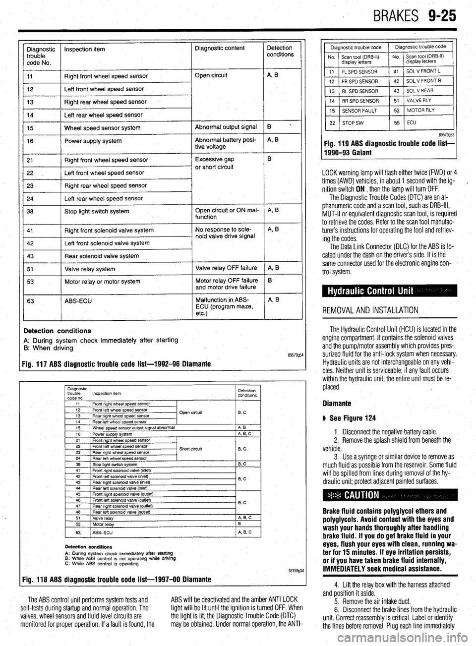
89579954 Fig. 117 ABS diagnostic trouble code list-1992-96 Diamante
Diagnostrc
trouble Inspection item Detectron
code no. condalons
1
11 1 Front right wheel speed SensOr
I
I I
12 1 Front left wheel speed sensor
13 1 Rear right wheel speed sensor Open circuit
lBsC I
14
Rear left wheel speed sensor
15 Wheel speed sensor output signal abnormal
16 Power supply system
21 Front right wheel speed sensor A B
A, B, C
22 Front left wheel speed sensor
23 Rear right wheel speed sensor
24 Rear left wheel speed sensor
38 Stop light switch system Short circuit
8, c
B. C
41 1 Front right solenoid valve (inlet)
I I
42
Front left solenoid valve (inlet)
43 Rear right solenord valve (inlet) 0.c
44 Rear left solenoid valve (inlet)
45 Front right solenoid valve (outlet)
46 Front left solenoid valve (outlet)
47
Rear nght solenoid valve (outret) - B,C
48 Rear left solenoid valve (outlet)
51
Valve relay A 6, c
53
Motor relay B
63 ABSECU A B, c
Detection conditions
A: During system check immediately after starting 6: While ABS control is not operating while driving C: While ABS control is operating 93159go4 Fig. 118 ABS diagnostic trouble code list-1997-00 Diamante
The ABS control unit performs system tests and
self-tests during startup and normal operation. The
valves, wheel sensors and fluid level circuits are
monitored for proper operation. If a fault is found, the ABS will be deactivated and the amber ANTI LOCK
light will be lit until the ignition is turned OFF. When
the light is lit, the Diagnostic Trouble Code (DTC)
may be obtained. Under normal operation, the ANTI-
89579g53 Fig. 119 ABS diagnostic trouble code list-
1990-93 Galant
LOCK warning lamp will flash either twice (FWD) or 4
times (AWD) vehicles, in about 1 second with the ig-
,
nition switch ON , then the lamp will turn OFF.
The Diagnostic Trouble Codes (DTC) are an al-
phanumeric code and a scan tool, such as DRB-III,
MUT-II or equivalent diagnostic scan tool, is required
to retrieve the codes. Refer to the scan tool manufac-
turers instructions for operating the tool and retriev-
ing the codes.
The Data Link Connector (DLC) for the ABS is lo-
cated under the dash on the driver’s side. It is the
same connector used for the electronic engine con-
trol system.
REMOVALANDINSTALLATION
The Hydraulic Control Unit (HCU) is located in the
engine compartment. It contains the solenoid valves
and the pump/motor assembly which provides pres-
surized fluid for the anti-lock system when necessary.
Hydraulic units are not interchangeable on any vehi-
cles Neither unit is serviceable; if any fault occurs
within the hydraulic unit, the entire unit must be re-
placed.
Diamante
b See Figure 124
1. Disconnect the negative battery cable.
2. Remove the splash shield from beneath the
vehicle.
3. Use a syringe or similar device to remove as
much fluid as possible from the reservoir. Some fluid
will be spilled from lines during removal of the hy-
draulic unit; protect adjacent painted surfaces.
Brake fluid contains polyglycol ethers and
poly9lycols. Avoid contact with the eyes and
wash your hands thoroughly after handling
brake fluid. If you do 9et brake fluid in your
eyes, flush your eyes with clean, running wa-
ter for 15 minutes. If eye irritation persists,
or if you have taken brake fluid internally,
IMMEDIATELY seek medical assistance.
4. Lift the relay box with the harness attached
and position it aside.
5. Remove the air intake duct.
6. Disconnect the brake lines from the hydraulic
unit. Correct reassembly is critical. Label or identify
the lines before removal. Plug each line immediately
Page 383 of 408
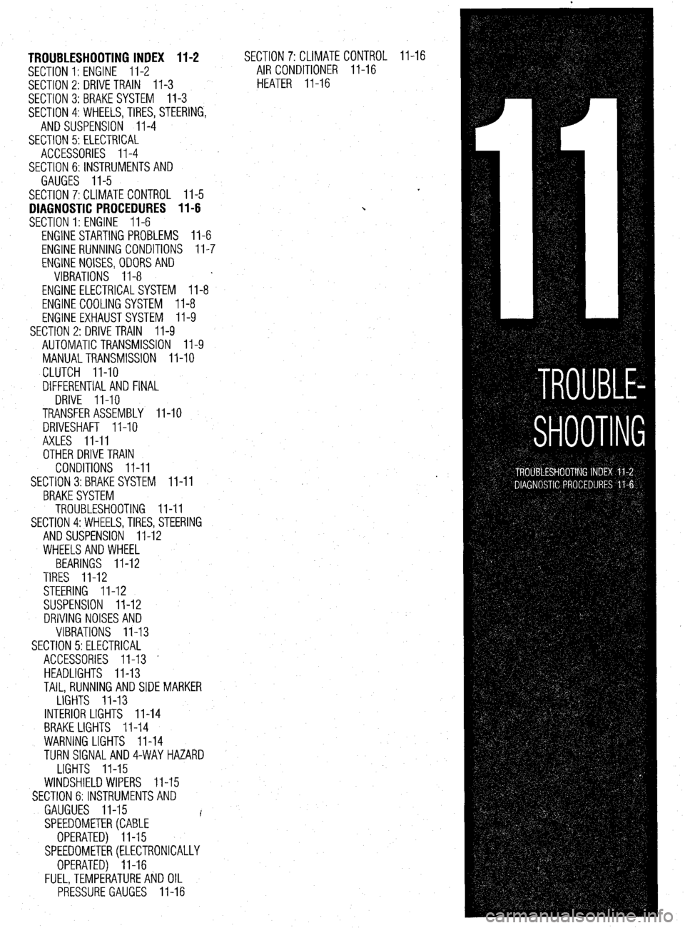
TROUBLESHOOTING INDEX 11-2
SECTION 1: ENGINE 11-2
SECTION 2: DRIVE TRAIN
11-3
SECTION 3:BRAKESYSTEM 11-3
SECTION 4:WHEELS,TIRES, STEERING,
AND SUSPENSION II-4
SECTION 5: ELECTRICAL
ACCESSORIES II-4
SECTION 6:lNSTRUMENTSAND
GAUGES II-5
SECTION 7:CLlMATE CONTROL II-5
DIAGNOSTIC PROCEDURES II-6
SECTION 1: ENGINE II-6
ENGINE STARTING PROBLEMS II-6
ENGINE RUNNING CONDITIONS II-7
ENGINE NOISES,ODORSAND
VIBRATIONS II-8
ENGINE ELECTRICALSYSTEM 11-8
ENGINE COOLING SYSTEM II-8
ENGINE EXHAUSTSYSTEM II-9
SECTION 2: DRIVE TRAIN
II-9
AUTOMATIC TRANSMISSION II-9
MANUALTRANSMISSION II-10
CLUTCH II-10
DIFFERENTIAL AND FINAL
DRIVE II-10
TRANSFER ASSEMBLY II-10
DRIVESHAFT II-10
AXLES II-II
OTHER DRIVE TRAIN
CONDITIONS II-II
SECTION 3:BRAKE SYSTEM II-II
BRAKESYSTEM
TROUBLESHOOTING II-II
SECTION 4:WHEELS, TIRES, STEERING
AND SUSPENSION II-12
WHEELSAND WHEEL
BEARINGS II-12
TIRES II-12
STEERING II-12
SUSPENSION II-12
DRIVING NOISES AND
VIBRATIONS II-13
SECTION 5:ELECTRlCAL
ACCESSORIES II-13 -
HEADLIGHTS II-13
TAIL, RUNNING AND SIDE MARKER
LIGHTS II-13
INTERIOR LIGHTS II-14
BRAKE LIGHTS II-14
WARNING LIGHTS II-14
TURN SlGNALAND4-WAYHAZARD
LIGHTS II-15
WINDSHIELD WIPERS II-15
SECTION 6:lNSTRUMENTSAND
GAUGUES II-15
I
SPEEDOMETER(CABLE
OPERATED) II-15
SPEEDOMETER(ELECTRONICALLY
OPERATED) II-16
FUEL,TEMPERATUREAkJD OIL
PRESSURE GAUGES II-16 SECTION 7:CLlMATECON
AIR CONDITIONER ll-
HEATER II-16 TR(
-16 IL II-16
Page 386 of 408
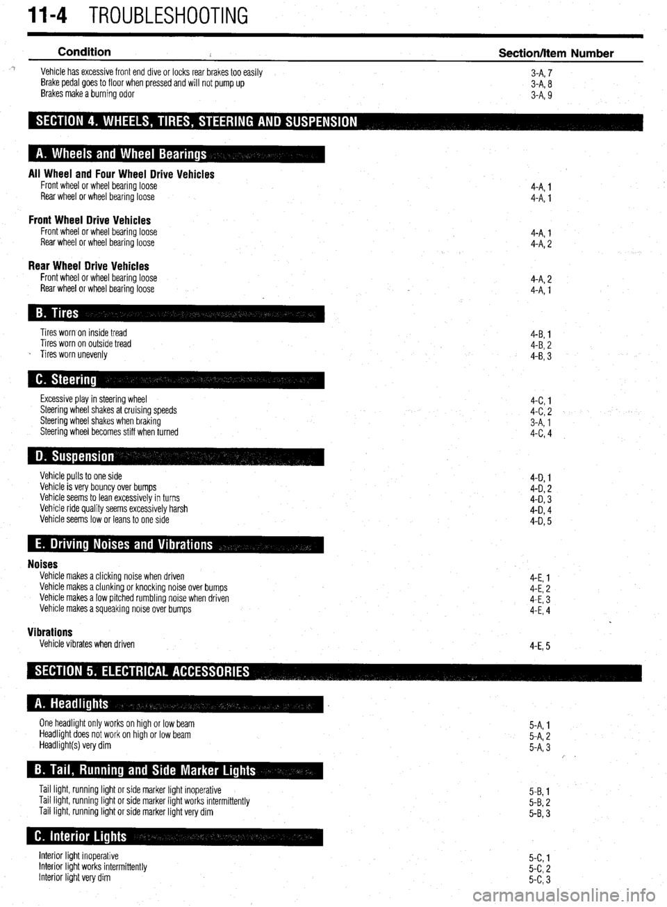
11-4 TROUBLESHOOTING
Condition
2 Section/Item Number ^i Vehicle has excessive front end dive or locks rear brakes too easily
3-A, 7
Brake pedal goes to floor when pressed and will not pump up
3-A, 8
Brakes make a burning odor
3-A, 9
All Wheel and Four Wheel Drive Vehicles Front wheel or wheel bearing loose
Rear wheel or wheel bearingloose
Front Wheel Drive Vehicles Front wheel or wheel bearing loose
Rear wheel or wheel bearing loose 4-A. 1
4-A: 1
4-A, 1
4-A, 2
Rear Wheel Drive Vehicles Front wheel or wheel bearing loose
Rear wheel or wheel bearing loose 4-A, 2
4-A, 1
Tires worn on inside tread
Tires worn on outside tread
s Tires worn unevenly 4-B, 1
4-B, 2
4-B, 3
Excessive play in steering wheel
Steering wheel shakes at cruising speeds
Steering wheel shakes when braking
Steering wheel becomes stiff when turned 4-c, 1
4-c, 2
3-A, 1
4-c, 4
Vehicle pulls to one side
Vehicle is very bouncy over bumps
Vehicle seems to lean excessively in turns
Vehicle ride quality seems excessively harsh
Vehicle seems low or leans to one side 4-D 1
4-D, 2
4-D, 3
4-D, 4
4-D, 5
Noises Vehicle makes a clicking noise when driven
Vehicle makes a clunking or knocking noise over bumps
Vehicle makes a low pitched rumbling noise when driven
Vehicle makes a squeaking noise over bumps
Vibrations Vehicle vibrates when driven 4-E, 1
4-E, 2
4-E, 3
4-E, 4
4-E, 5
One headlight only works on high or low beam
Headlight does not work on high or low beam
Headlight(s) very dim
Tail light, running light or side marker light inoperative
Tail light, running light or side marker light works intermittently
Tail light, running light or side marker light very dim 5-A, 1
5-A, 2
5-A, 3
/ .
5-B, 1
5-B, 2
5-B, 3
Interior light inoperative
Interior light works intermittently
Interior light very dim 5-c, 1
5-c, 2
5-c, 3
Page 387 of 408
.
TROUBLESHOOTING II-5
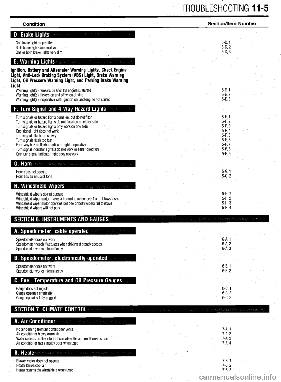
Condition Section/Item Number
One brake light inoperative
Both brake lights inoperative
One or both brake lights very dim 5-D, 1
5-D, 2
5-D, 3
Ignition, Battery and Alternator Warning Lights, Check Engine
Light, Anti-Lock Braking System (ABS) Light, Brake Warning
Light, Oil Pressure Warning Light, and Parking Brake Warning
Light
Warning light(s) remains on after the engine is started
Warning light(s) flickers on and off when driving
Warning light(s) inoperative with ignition on, and engine not started 5-E, 1
5-E, 2
5-E, 3
Turn signals or hazard lights come on, but do not flash
Turn signals or hazard lights do not function on either side
Turn signals or hazard lights only work on one side
One signal light does not work
Turn signals flash too slowly
Turn signals flash too fast
Four-way hazard flasher indicator light inoperative
Turn signal indicator light(s) do not work in either direction
One turn signal indicator light does not work 5-F, 1
5-F, 2
5-F, 3
5-F, 4
5-F, 5
5-F, 6
5-F, 7
5-F, 8
5-F, 9
Horn does not operate
Horn has an unusual tone 5-G, 1
5-G, 2
Windshield wipers do not operate
Windshield wiper motor makes a humming noise, gets hot or blows fuses
Windshield wiper motor operates but one or both wipers fail to move
Windshield wipers will not park 5-H, 1
5-H, 2
5-H, 3
5-H, 4
Speedometer does not work
Speedometer needle fluctuates when driving at steady speeds
Speedometer works intermittently 6-A, 1
6-A, 2
6-A, 3
Speedometer does not work
Speedometer works intermittently 6-B, 1
6-B, 2
Gauge does not register 6-C 1
Gauge operates erratically 6-C 2
’
Gauge operates fully pegged 6-C 3
No air coming from air conditioner vents 7-A, 1
Air conditioner blows warm air ’ 7-A, 2
Water collects on the interior floor when the air conditioner is used
Air conditioner has a moldy odor when used 7-A, 3
7-A, 4
Blower motor does not operate
Heater blows cool air
Heater steams the windshield when used 7-B, 1
7-B, 2
7-B, 3
Page 395 of 408
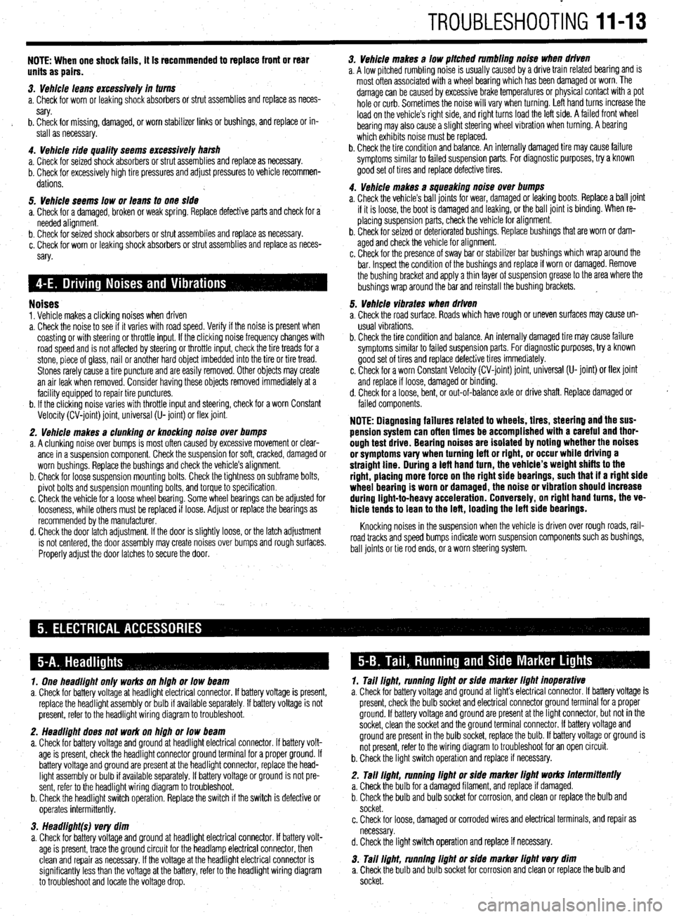
TROUBLESHOOTING 11-13
NOTE: When one shock fails, ft is recommended to replace front or rear
units as pairs.
3. Vehicle leans excessively in turns
a. Check for worn or leaking shock absorbers or strut assemblies and replace as neces-
sary.
b. Check for missing, damaged, or worn stabilizer links or bushings, and replace or in-
stall as necessary.
4. Vehicle ride quality seems excessively ha&h
a. Check for seized shock absorbers or strut assemblies and replace as necessary.
b. Check for excessively high tire pressures and adjust pressures to vehicle recommen-
dations.
5. Vehicle seems low or leans to one side
a. Check for a damaged, broken or weak spring. Replace defective parts and check for a
needed alignment.
b. Check for seized shock absorbers or strut assemblies and replace as necessary.
c. Check for worn or leaking shock absorbers or strut assemblies and replace as neces-
sary.
Noises 1. Vehicle makes a clicking noises when driven
a. Check the noise to see if it varies with road speed. Verify if the noise is present when
coasting or with steering or throttle input. If the clicking noise frequency changes with
road speed and is not affected by steering or throttle input, check the tire treads for a
stone, piece of glass, nail or another hard object imbedded into the tire or tire tread.
Stones rarely cause a tire puncture and are easily removed. Other objects may create
an air leak when removed. Consider having these objects removed immediately at a
facility equipped to repair tire punctures.
b. If the clicking noise varies with throttle input and steering, check for a worn Constant
Velocity (CV-joint) joint, universal (U- joint) or flex joint.
2. Vehicle makes a clunking or knocking noise over bumps
a. A clunking noise over bumps is most often caused by excessive movement or clear-
ance in a suspension component. Check the suspension for soft, cracked, damaged or
worn bushings. Replace the bushings and check the vehicle’s alignment.
b. Check for loose suspension mounting bolts. Check the tightness on subframe bolts,
pivot bolts and suspension mounting bolts, and torque to specification.
c. Check the vehicle for a loose wheel bearing. Some wheel bearings can be adjusted for
looseness, while others must be replaced if loose. Adjust or replace the bearings as
recommended by the manufacturer.
d. Check the door latch adjustment. If the door is slightly loose, or the latch adjustment
is not centered, the door assembly may create noises over bumps and rough surfaces.
Properly adjust the door latches to secure the door. 3. Vehicle makes a low pitched rumbling noise when driven
a. A low pitched rumbling noise is usually caused by a drive train related bearing and is
most often associated with a wheel bearing which has been damaged or worn. The
damage can be caused by excessive brake temperatures or physical contact with a pot
hole or curb. Sometimes the noise will vary when turning. Left hand turns increase the
load on the vehicle’s right side, and right turns load the left side. A failed front wheel
bearing may also cause a slight steering wheel vibration when turning. A bearing
which exhibits noise must be replaced.
b. Check the tire condition and balance. An internally damaged tire may cause failure
symptoms similar to failed suspension parts. For diagnostic purposes, try a known
good set of tires and replace defective tires.
4. Vehicle makes a squeaking noise over bumps
a. Check the vehicle’s ball joints for wear, damaged or leaking boots. Replace a ball joint
if it is loose, the boot is damaged and leaking, or the ball joint is binding. When re-
placing suspension parts, check the vehicle for alignment.
b. Check for seized or deteriorated bushings. Replace bushings that are worn or dam-
aged and check the vehicle for alignment.
c. Check for the presence of sway bar or stabilizer bar bushings which wrap around the
bar. Inspect the condition of the bushings and replace if worn or damaged. Remove
the bushing bracket and apply a thin layer of suspension grease to the area where the
bushings wrap around the bar and reinstall the bushing brackets. ~
5. Vehicle vibrates when driven
a. Check the road surface. Roads which have rough or uneven surfaces may cause un-
usual vi brations.
b. Check the tire condition and balance. An internally damaged tire may cause failure
symptoms similar to failed suspension parts. For diagnostic purposes, try a known
good set of tires and replace defective tires immediately.
c. Check for a worn Constant Velocity (CV-joint) joint, universal (U- joint) or flex joint
and replace if loose, damaged or binding.
d. Check for a loose, bent, or out-of-balance axle or drive shaft. Replace damaged or
failed components.
NOTE: Diagnosing failures related to wheels, tires, steering and the sus-
pension system can often times be accomplished with a careful and thor-
ough test drive. Bearing noises are isolated by noting whether the noises
or symptoms vary when turning left or right, or occur while driving a
straight line. During a teft hand turn, the vehicle’s weight shifts to the
right, placing more force on the right side bearings, such that if a right side
wheel bearing is worn or damaged, the noise or vibration should increase
during light-to-heavy acceleration. Conversely, on right hand turns, the ve-
hicle tends to lean to the left, loading the left side bearings.
Knocking noises in the suspension when the vehicle is driven over rough roads, rail-
road tracks and speed bumps indicate worn suspension components such as bushings,
ball joints or tie rod ends, or a worn steering system.
1. One headlight only works on high or low beam
a. Check for battery voltage at headlight electrical connector. If battery voltage is present,
replace the headlight assembly or bulb if available separately. If battery voltage is not
present, refer to the headlight wiring diagram to troubleshoot.
2. Headlight does not work on high or low beam
a. Check for battery voltage and ground at headlight electrical connector. If battery volt-
age is present, check the headlight connector ground terminal for a proper ground. If
battery voltage and ground are present at the headlight connector, replace the head-
light assembly or bulb if available separately. If battery voltage or ground is not pre-
sent, refer to the headlight wiring diagram to troubleshoot.
b. Check the headlight switch operation. Replace the switch if the switch is defective or
ooerates intermittentlv. 1. Tail light, running light or side marker light inoperative
a. Check for battery voltage and ground at light’s electrical connector. If battery voltage is
present, check the bulb socket and electrical connector ground terminal for a proper
ground. If battery voltage and ground are present at the light connector, but not in the
socket, clean the socket and the ground terminal connector. If battery voltage and
ground are present in the bulb socket, replace the bulb. If battery voltage or ground is
not present, refer to the wiring diagram to troubleshoot for an open circuit.
b. Check the light switch operation and replace if necessary.
2. Tall light, running light or side marker light works intermittently
a. Check the bulb for a damaged filament, and replace if damaged.
b. Check the bulb and bulb socket for corrosion, and clean or replace the bulb and
socket.
w 3. Headlight(s) very dim
a. Check for battery voltage and ground at headlight electrical connector. If battery volt-
age is present, trace the ground circuit for the headlamp electrical connector, then
clean and repair as necessary. If the voltage at the headlight electrical connector is
significantly less than the voltage at the battery, refer to the headlight wiring diagram
to troubleshoot and locate the voltage drop. c. Check for loose, damaged or corroded wires and electrical terminals, and repair as
necessary.
d. Check the light switch operation and replace if necessary.
3. Tail light, running light or side marker light very dim
a. Check the bulb and bulb socket for corrosion and clean or replace the bulb and
socket.