1900 MITSUBISHI DIAMANTE wiring
[x] Cancel search: wiringPage 120 of 408
ENGINEAND ENGINEOVERHAUL 3-59
Most of the cleaning process can be carried out
with common hand tools and readily available sol-
vents or solutions. Carbon deposits can be chipped
away using a hammer and a hard wooden chisel. Old
gasket material and varnish or sludge can usually be
removed using a scraper and/or cleaning solvent. Ex-
tremely stubborn deposits may require the use of a
power drill wrth a wire brush. If using a wire brush,
use extreme care around any critical machined sur-
faces (such as the gasket surfaces, bearing saddles,
cylinder bores, etc.). USE OF A WIRE BRUSH IS NOT
RECOMMENDED ON ANY ALUMINUM COMPO-
NENTS Always follow any safety recommendations
given by the manufacturer of the tool and/or solvent.
You should always wear eye protection during any
cleaning process involvrng scraping, chipping or
spraying of solvents.
An alternative to the mess and hassle of cleaning
the parts yourself is to drop them off at a local garage
or machine shop. They will, more than likely, have
the necessary equrpment to properly clean all of the
parts for a nominal fee.
Always wear eye protection during any clean-
ing process involving scraping, chipping or
spraying of solvents.
Remove any oil galley plugs, freeze plugs and/or
pressed-in bearings and carefully wash and degrease
all of the engine components including the fasteners
and bolts. Small parts such as the valves, springs,
etc., should be placed in a metal basket and allowed
to soak. Use pipe cleaner type brushes, and clean all
passageways in the components. Use a ring ex-
pander and remove the rings from the pistons. Clean
the piston ring grooves with a special tool or a piece
of broken ring Scrape the carbon off of the top of the
piston. You should never use a wire brush on the
pistons. After preparing all of the piston assemblies
in this manner, wash and degrease them again.
Use extreme care when cleaning around the
cylinder head valve seats. A mistake or slip
may cost you a new seat.
When cleaning the cylinder head, remove carbon
from the combustron chamber with the valves in-
stalled. This will avoid damaging the valve seats.
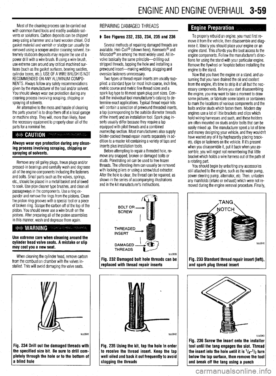
:ig. 234 Drill out the damaged threads with
he specified size bit. Be sure to drill corn.
rletely through the hole or to the bottom oi
I blind hole REPAIRING DAMAGEDTHREADS
# See Figures 232, 233, 234, 235 and 236
Several methods of repairing damaged threads are
available Heli-Coil@ (shown here), Keenserts@ and
Microdop are among the most widely used. All in-
volve basically the same principle-drilling out
stripped threads, tapping the hole and installing a
prewound insert-making welding, plugging and
oversize fasteners unnecessary.
Two types of thread repair inserts are usually sup-
plied: a standard type for most inch coarse, rnch fine,
metric course and metrrc fine thread sizes and a
spark lug type to fit most spark plug port sizes. Con-
sult the individual tool manufacturers catalog to de-
termine exact applications. Typical thread repair kits
will contain a selection of prewound threaded inserts,
a tap (corresponding to the outside diameter threads
of the insert) and an installation tool. Spark plug in-
serts usually differ because they require a tap
equipped wrth pilot threads and a combined
reamer/tap section. Most manufacturers also supply
blister-packed thread repair Inserts separately in ad-
dition to a master kit containing a variety of taps and
inserts plus installation tools
Before attempting to repair a threaded hole, re-
move any snapped, broken or damaged bolts or
studs. Penetrating oil can be used to free frozen
threads. The offending item can usually be removed
with locking pliers or using a screw/stud extractor.
After the hole is clear, the thread can be reparred, as
shown in the series of accompanying illustrations
and in the krt manufacturers instructions.
THREADED
lCCS3039
replaced with thread repair inserts
:ig. 235 Using the kit, tap the hole in order
o receive the thread insert. Keep the tap
veil oiled and back it out frequently to avoid
:logging the threads
To properly rebuild an engine, you must first re-
move it from the vehicle, then disassemble and diag-
nose it. Ideally you should place your engine on an
engine stand. This affords you the best access to the
engine components. Follow the manufacturers direc-
tions for using the stand with your particular engine.
Remove the flywheel or flexplate before installing the
engine to the stand.
Now that you have the engine on a stand, and as-
suming that you have drained the oil and coolant
from the engine, it’s time to strip it of all but the nec-
essary components. Before you start disassembling
the engine, you may want to take a moment to draw
some pictures, or fabricate some labels or containers
to mark the locations of various components and the
bolts and/or studs which fasten them. Modern day
engines use a lot of little brackets and clips which
hold wiring harnesses and such, and these holders
are often mounted on studs and/or bolts that can be
easily mixed up. The manufacturer spent a lot of time
and money designing your vehicle, and they wouldn’t
have wasted any of it by haphazardly placing brack-
ets, clips or fasteners on the vehicle. If it’s present
when you disassemble it, put it back when you as-
semble, you will regret not remembering that little
bracket which holds a wire harness out of the path of
a rotating part.
You should begin by unbolting any accessories
still attached to the engine, such as the water pump,
power steering pump, alternator, etc. Then, unfasten
any manifolds (intake or exhaust) which were not re-
moved during the engine removal procedure. Finally,
Fig. 233 Standard thread repair insert (left),
and spark plug thread insert
im3043 Fig. 236 Screw the insert onto the installer
1001 until the tang engages the slot. Thread
‘he insert into the hole until it is l/4-l/~ turn
lelow the top surface, then remove the tool
and break off the tano usina a uunch
Page 151 of 408
.
4-8 DRIVEABILITYAND EMISSIONS CONTROLS
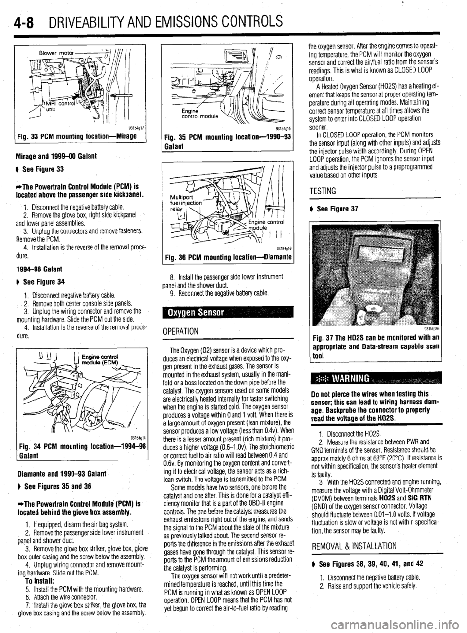
93154g17 Fig. 33 PCM mounting location-Mirage
Mirage and 1999-00 Galant
) See Figure 33
*The Powertrain Control Module (PCM) is
located above the passenger side kickpanel.
1. Disconnect the negative battery cable.
2. Remove the @love box, right side kickpanel
and lower panel assemblies.
3. Unplug the connectors and remove fasteners.
Remove the PCM.
4. Installation is the reverse of the removal proce-
dure.
1994-98 Galant
+ See Figure 34
1, Disconnect negative battery cable.
2. Remove both center console side panels.
3. Unplug the wiring connector and remove the
mounting hardware. Slide the PCM out the side.
4. installation is the reverse of the removal proce-
dure.
Diamante and 1990-93 Galant
) See Figures 35 and 38
*The Powertrain Control Module (PCM) is
located behind the glove box assembly.
1, If equipped, disarm the air bag system
2. Remove the passenger side lower instrument
panel and shower duct.
3. Remove the glove box striker, glove box, glove
box outer casing and the screw below the assembly.
4. Unplug wiring connector and remove mount-
ing hardware. Slide out the PCM.
To install: 5. Install the PCM with the mounting hardware.
6. Attach the wire connector.
7. Install the glove box striker, the glove box, the
glove box casing and the screw below the assembly.
Q3154g15 Fig. 35 PCM mounting location-1990-93
Galant
93154g16 Fig. 38 PCM mounting location-Diamante
8. Install the passenger side lower instrument
panel and the shower duct.
9. Reconnect the negative battery cable
OPERATION
The Oxygen (02) sensor is a device which pro-
duces an electrical voltage when exposed to the oxy-
gen present in the exhaust gases. The sensor is
mounted in the exhaust system, usually in the mani-
fold or a boss located on the down pipe before the
catalyst. The oxygen sensors used on some models
are electrically heated internally for faster switching
when the engine is started cold. The oxygen sensor
produces a voltage within 0 and 1 volt. When there is
a large amount of oxygen present (lean mixture), the
sensor produces a low voltage (less than 0.4~). When
there is a lesser amount present (rich mixture) it pro-
duces a higher voltage (0.6-I .Ov). The stoichiometric
or correct fuel to air ratio will read between 0.4 and
0.6~. By monitoring the oxygen content and convert-
ing it to electrical voltage, the sensor acts as a rich-
lean switch. The voltage is transmitted to the PCM.
Some models have two sensors, one before the
catalyst and one after. This is done for a catalyst eff i-
ciency monitor that is a part of the OBD-II engine
controls. The one before the catalyst measures the
exhaust emissions right out of the engine, and sends
the signal to the PCM about the state of the mixture
as previously talked about. The second sensor re-
ports the difference in the emissions after the exhaust
gases have gone through the catalyst. This sensor re-
ports to the PCM the amount of emissions reduction
the catalyst is performing.
The oxygen sensor will not work until a predeter-
mined temperature is reached, until this time the
PCM is running in what as known as OPEN LOOP
operation. OPEN LOOP means that the PCM has not
yet begun to correct the air-to-fuel ratio by reading the oxygen sensor. After the engine comes to operat-
ing temperature, the PCM will monitor the oxygen
sensor and correct the air/fuel ratio from the sensor’s
readings. This is what is known as CLOSED LOOP
operation.
A Heated Oxygen Sensor (H02S) has a heating el-
ement that keeps the sensor at proper operatmg tem-
perature during all operating modes. Maintaining
correct sensor temperature at all times allows the
system to enter into CLOSED LOOP operation
sooner.
In CLOSED LOOP operation, the PCM monitors
the sensor input (along with other inputs) and adjusts
the injector pulse width accordingly. During OPEN
LOOP operation, the PCM ignores the sensor input
and adjusts the injector pulse to a preprogrammed
value based on other inputs.
TESTING
# See Figure 37
93154p36 Fig. 37 The HD2S can be monitored with an
appropriate and Data-stream capable scan
tool
Do not pierce the wires when testing this
sensor; this can lead to wiring harness dam-
age. Backprobe the connector to properly
read the voltage of the HD2S.
1. Disconnect the H02S.
2. Measure the resistance between PWR and
GND terminals of the sensor. Resistance should be
approximately 6 ohms at 68°F (20°C) If resistance is
not within specification, the sensor’s heater element
is faulty.
3. With the H02S connected and engine running,
measure the voltage with a Digital Volt-Ohmmeter
(DVOM) between terminals
HD2S and SIG RTN (GND) of the oxygen sensor connector. Voltage
should fluctuate between 0.01-l .O volts. If voltage
fluctuation is slow or voltage is not within specifica-
tion, the sensor may be faulty.
REMOVAL &INSTALLATION
) See Figures 38, 39, 40, 41, and 42
1. Disconnect the negative battery cable
2. Raise and support the vehicle safely.
Page 152 of 408
DRIVEABILITYAND EMISSIOP JSCONTRiLS 4-9
3. Label and disconnect the H02S from the en-
gine control wiring harness.
*Lubricate the sensor with penetrating oil
prior to removal.
4. Remove the sensor using an oxygen sensor
I To install: - -v- -- ---- ..----. ----...= -..- r... *-
5. Install the sensor in the mounting boss and
hl-li)r\,,.l 0 ,.l.-.f.l, .T‘fi.LI wrench or another suitable tool.
tighten to 27-33 ft. Ibs. (37-45 Nm).
6. Connect the engine control wiring harness to 1 Fia. 43 IAC mntnr tnfitinn and nin Incations 1
KtMUVHL i% IN3 I ALLA I IUN
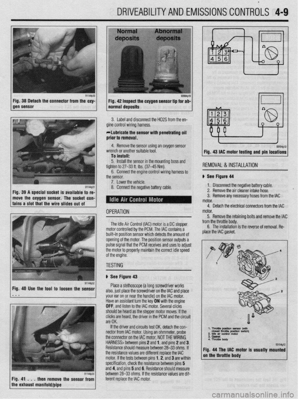
See Fiaurr! d4
1. Disconnect the negative battery cable.
2. Remove the air cleaner intake hose.
move the oxygen sensor. The socket con- 3. Remove any necessary hoses from the IAC
OPERATION
The Idle Air Control (IAC) motor is a DC stepper
motor controlled by the PCM. The IAC contains a
built-in position sensor which detects the amount of
opening of the motor. The position sensor outputs a
pulse signal that the PCM receives and uses to adjust
the motor to properly maintain the correct idle speed
of the engine. motor.
5. Remove the retainino bolts and remove the IAC
y -_.._ -..- ._... -._ . .._ ._ from the throttle body. C The inc.hllrrti~n a 11o IIIJL(IIIoLIuII is the reverse of removal. Re-
plaie the IAC gasket.
TESTING
I
ti See Figure 43
Place a stethoscope (a long screwdriver works
also, just place the screwdriver on the IAC and place
your ear on or near the handle) on the IAC motor.
Have an assistant turn the key ON with the engine
OFF, and listen to the IAC motor. Several clicks
should be heard as the steooer motor moves. If the
clicks are heard, the driver in the PCM and the circuit
are OK.
If the driver and circuits test OK, detach the con-
nectar from IAC motor. Using an ohmmeter, probe ‘. l-!AEz?rn~ -w
2 Idle an conh0l motor nswltch)
the connector on the IAC motor, NOT THE WIRING
HARNESS> between pins 2 and 1, and pins 2 and 3.
Resistance should measure between 26-33 ohms. If
the resistance values are different replace the IAC tor is usually mounted
motor. If the tests between pins 1,2, and 3 are within
specification, check the resistance between pins 5
and 4, and pins 5 and 6. Resistance should measure
between 26-33 ohms. If the resistance values are dif-
then remove the sensor from ferent replace the IAC motor.
Page 153 of 408
4-10 DRIVEABILITYAND EMISSIONS CONTROLS
I
OPERATION
The Engine Coolant Temperature (ECT) sensor re-
sistance changes in response to engine coolant tem-
perature. The sensor resistance decreases as the
coolant temperature increases, and increases as the
coolant temperature decreases. This provides a refer-
ence signal to the PCM, which indicates engine
coolant temperature. The signal sent to the PCM by
the ECT sensor helps the PCM to determine spark-
advance, EGR flow rate, air/fuel ratio, and engine
temperature. The ECT is a two wire sensor, a 5volt
3. Place the temperature sensing portion of the
sensor into a pan of hot water. Use a thermometer to
monitor the water temperature.
4. Measure the resistance across the sensor ter-
minals while the sensor is in the water. Comoare ob- Fig. 47 Another method of testing the EC1 Fig. 50 Use a deep socket and an extension
is to submerge it in cold or hot water and to reach the ECT sensor. 1 ,
reference signal is sent to the sensor and the signal
return is based upon the change in the measured re-
sistance due to temperature. 1 check resistance
TESTING
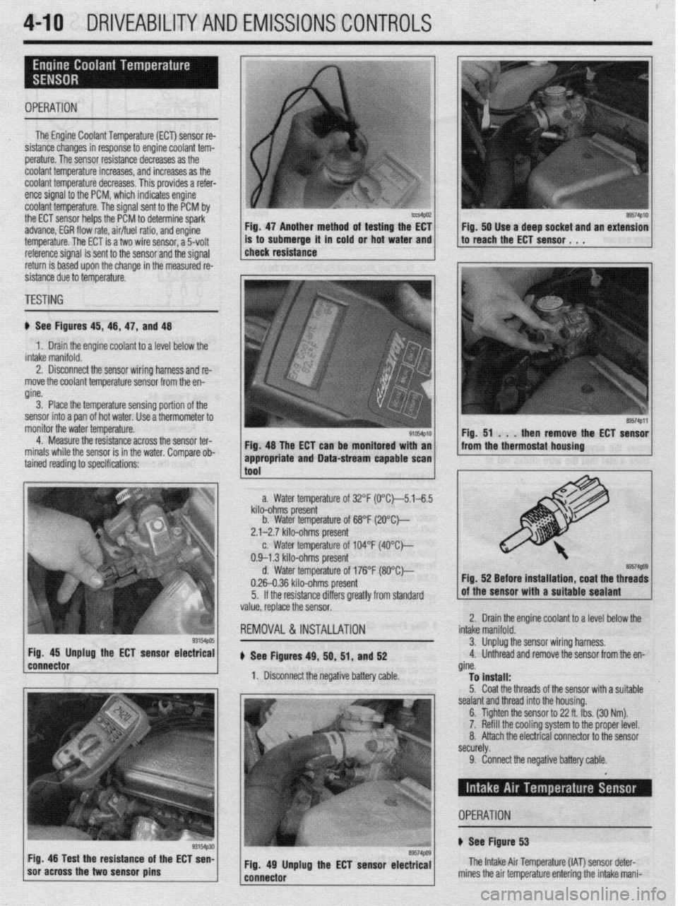
ti See Figures 45, 46, 47, and 48
1. Drain the engine coolant to a level below the
intake manifold.
2. Disconnect the sensor wiring harness and re-
move the coolant temperature sensor from the en-
gine.
Fig. 48 The ECT can be monitored with an
tained reading to specifications: ’
93154pos Fig. 45 Unplug the ECT sensor electrical
connector
1 soracross the two sensor pins g3154p30 Fig 48 Test the resistance of the ECT sen-
89574PlO
89574Pll
Fig. 51 . . .
then remove the ECT sensor
from the thermostat housing
a. Water temperature of 32°F (0°C~5.1-6.5
kilo-ohms present
b. Water temperature of 68°F (2O”C)--
2.1-2.7 kilo-ohms present
c. Water temperature of 104°F (4O”C)---
0.9-l .3 kilo-ohms present
d. Water temperature of 176°F (8O”Ck,
0.26-0.36 kilo-ohms present
5. If the resistance differs greatly from standard
value, replace the sensor.
REMOVAL &INSTALLATION
u See Figures 49, 50, 51, and 52
1. Disconnect the negative battery cable. Fig. 52 Before installation, coat the threads
Iolant to a level below the 2. Drain the engine c(
intake manifold.
3. Unplug1 the sensor wiring harness,
4. Unthreac
d and remove the sensor from the en-
gine.
To install:
5. Coat the threads of the sensor with a suitable
sealant and thread into the housing.
6. Tighten the sensor to 22 ft. Ibs. (30 Nm).
7. Refill the cooling system to the proper level.
8. Attach the electrical connector to the sensor
securely. appropriate and Data-stream capable scan 1
1
tnnl
9. Connect the negative battery cable.
Fig. 49 Unplug the ECT sensor electrical
---..^-s-- The Intake Air Temperature (IAT) sensor det
mines the air temnerature enterinn the! intake n er-
- ._ r_ -.-._ _. ._. J . _ ..-. ._
iani- OPERATION
+ See Figure 53
Page 156 of 408
DRIVEABILITYAND EMISSIONS CONTROiS 4-13
4. If the voltaoe check in sbo 3 was OK. then
check the voltage-between GND’and SIG RTN termi-
nals and suddenly depress the accelerator, the volt-
age should rise and stay at 2.4 volts. If the voltage
OPERATION does not stay at 2.4 volts, replace the MAP sensor.
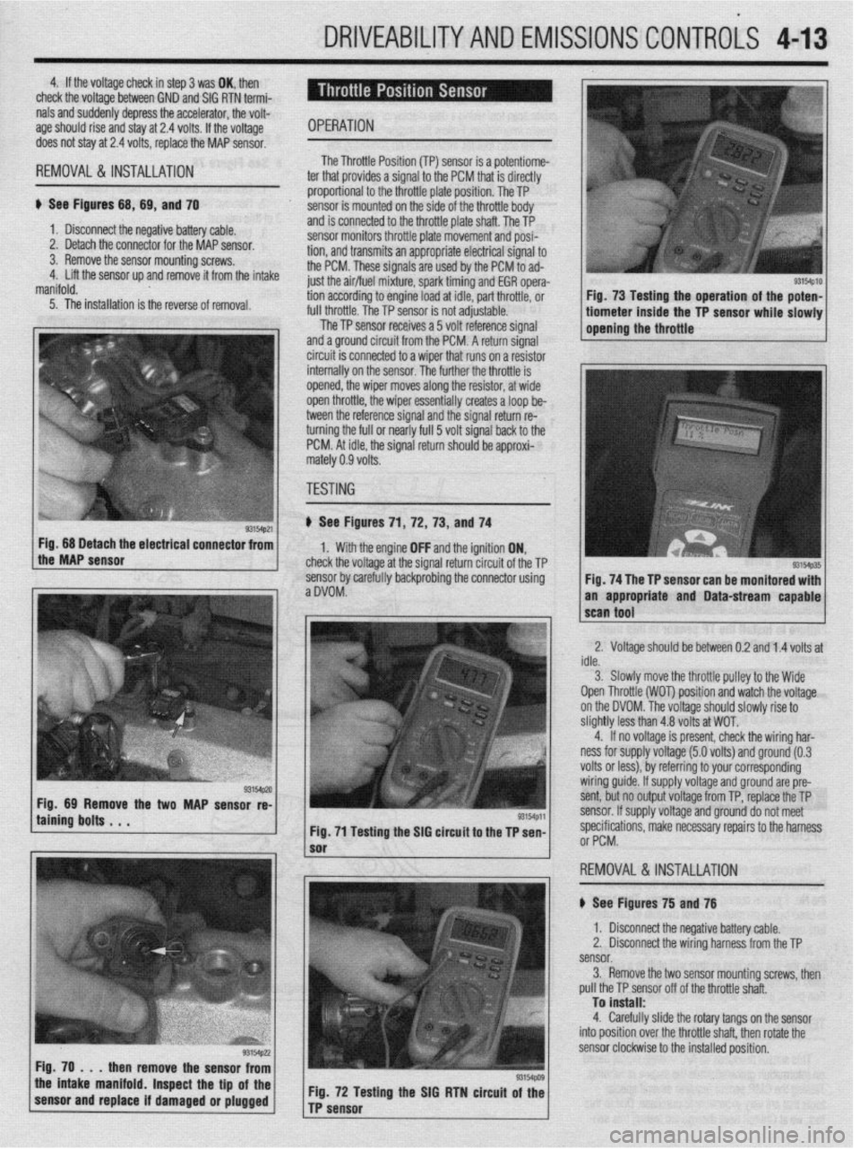
REMOVAL&INSTALLATION '
ti See Figures 68, 69, and 70
1. Disconnect the negative bat lery cable.
2. Detach the connector for thl e MAP sensor.
3. Remove the sensor mountir ig screws.
4. Lift the sensor up and remove it from the intake
manifold. The Throttle Posii
ti-* \*. Inn ITPl smsnr is 8 Dotentiome- , WI...,". *., . ter that provides a si gnal to the PCM that is directly
proportion: il to the throttle plate position. The TP
sensor is rr iounted on the side of the throttle body
and is connected to the throttle plate shaft. The TP
sensor monitors throttle plate movement and posi-
tion, and transmits an appropriate electrical signal to
the PCM. These signals grp IIQX-I hv rho PCM to ad-
just the air/flnI mivtlI “-- ------li
5. The installation is the reverse of removal. WI I dLfUl U full throttle The TP c
UyI ,,,,,,,:re, spark timing and EGR opera-
ng to engine load at idle, part throttle, or
The TP sensor is not adjustable.
..-
lensor receives a 5 volt reference signal
and a ground circuit from the PCM. A return signal
circuit is connected to a wiper that runs on a resistor
internally on the sensnr ThP fmth@r rho throttle is
opined the winnr mr oP -*lY”, .I,” ..,y’V, 111 Jves along the resistor, at wide
en throttle, the wiper essentially creates a loop be-
tween the reference signal and the signal return re-
turning the full or nearly full 5 volt signal back to the
PCM. At idle, the signal return should be approxi-
rnz
rtely 0.9 volts.
TF
iSTING
) See Figures 71 ,72, 73, and 74
1. With the engine OFF and the ignition ON,
check the voltage at the signal return circuit of the TP
sensor bv carefullv backorobina the connector using
aDVOM: . ” Fig. 68 Detach the electrical connector from
the MAP sensor
taining bolts . . . WMp,l
Fig. 71 Testing the SIG circuit to the TP sen-
then remove the sensor from
the intake manifold. Inspect the tip of the
sensor and replace if damaged or plugged Fig. 72 Testing the SIG RTN circuit of the
TP sensor
sm4p10 I Fig. 73 Testing the operation of the poten- 1
tiometer inside the TP sensor while slowly 1
opening the throttle
Fig. 74 The TP sensor can be monitored with
an appropriate and Data-stream capable
2. Voltage should be between 0.2 and 1.4 volts at
idle.
3. Slowlv move the throttle oullev to the Wide
Open Throttle (WOT) position and watch the voltage
on the DVOM. The voltage should slowly rise to
slightly less than 4.8 volts at WOT.
4. If no voltage is present, check the wiring har-
ness for supply voltage (5.0 volts) and ground (0.3
volts or less), by referring to your corresponding
wiring guide. If supply voltage and ground are pre-
sent, but no output voltage from TP, replace the TP
sensor. If supply voltage and ground do not meet
specifications, make necessarv reoairs to the harness
or PCM.
,
REMOVAL&INSTALLATION
# See Figures 75 and 76
1. Disconnect the negative battery cable.
2. Disconnect the wiring harness from the TP
sensor.
3. Remove the two sensor mounting screws, then
pull the TP sensor off of the throttle shaft.
To install:
4. Carefully slide the rotary tangs on the sensor
into position over the throttle shaft. then rotate the
sensor clockwise to the installed position.
Page 157 of 408
.
4-14 DRIVEABILITYAND EMISSIONS CONTROLS
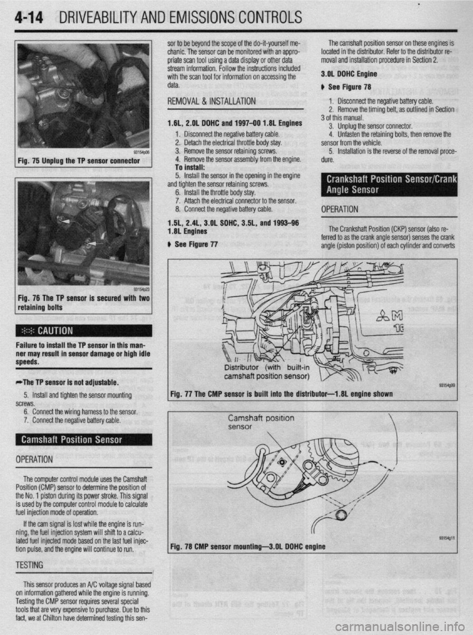
93154pm Fig. 75 Unplug the TP sensor connector
Fig. 76 The TP sensor is secured with two
retaining bolts sor to be beyond the scope of the do-it-yourself me- The camshaft position sensor on these engines is
chanic. The sensor can be monitored with an appro2 located in the distributor. Refer to the distributor re-
oriate scan tool usina a data disolav or other data moval and installation procedure in Section 2.
stream information. hollow the instructions included
with the scan tool for information on accessing the
data.
REMOVAL &INSTALLATION 3.01 DDHC Engine
p See Figure 78
1. Disconnect the negative battery cable.
2. Remove the timing belt, as outlined in Section
1,6L, 2.01 DDHC and 1997-00 I .8L Engines
1 I Disconnect the negative battery cable.
2. Detach the electrical throttle body stay.
3. Remove the sensor retaining screws.
4. Remove the sensor assembly from the engine.
To install:
5. Install the sensor in the opening in the engine
and tighten the sensor retaining screws.
6. Install the throttle body stay.
7. Attach the electrical connector to the sensor.
8. Connect the negative battery cable.
1.5L, 2.41, 3.OL SDHC, 3.5L, and 1993-96
1.8L Engines
ti See Figure 77 3 of this manual.
3. Unplug the sensor connector.
4. Unfasten the retaining bolts, then remove the
sensor from the vehicle.
5. Installation is the reverse of the removal proce-
dure.
OPERATION
The Crankshaft Position (CKP) sensor (also re-
ferred to as the crank angle sensor) senses the crank
angle (piston position) of each cylinder and converts
Failure to install the TP sensor in this man-
ner may result in sensor damage or high idle
speeds.
,
*The TP sensor is not adjustable. camshaft position sensor)
=1541po9 5. Install and tighten the sensor mounting
“n,zw.m JU cw3, 6. Connect the wiring harness to the sensor.
7. Connect the negative battery cable. Fig. 77 The CMP sensor Is built into the distributor-l .8L engine shown
Camshaft position
sensor
OPERATION
I
The computer control module uses the Camshaft
.
Position (CMP) sensor to determine the position of
the No. 1 piston during its power stroke. This signal
is used by the computer control module to calculate
fuel injection mode of operation.
If the cam signal is lost while the engine is run-
ning, the fuel injection system will shiffto a calcu-
lated fuel injected mode based on the last fuel injec-
93154gll
tion pulse, and the engine will continue to run. Fig. 78 CMP sensor mounting-3.01 DDHC engine
TESTbiG
This sensor produces an A/C voltage signal based
on information gathered while the engine is running.
Testing the CMP sensor requires several special
tools that are very expensive to purchase. Due to this
fact, we at Chilton have determined testing this sen-
Page 169 of 408
4-26 DRIVEABILITYAND EMISSIONS CONTROLS
The Powertrain Control Module (PCM) monitors
the signals of input and output sensors, some all the
time and others at certain times and processes each
signal. When the PCM notices that an irregularity has
continued for a specified time or longer from when
the irregular signal was initially monitored, the PCM
judges that a malfunction has occurred and will
memorize the malfunction code. The code is then
stored in the memory of the PCM and is accessible
through the data link (diagnostic connector) with the
use of an electronic scan tool or a voltmeter.
CHECK ENGINE/MALFUNCTION
INDICATOR LIGHT
Among the on-board diagnostic items, a check
engine/malfunction indicator light comes on to notify
the driver of a emission control component irregular-
ity. If the irregularity detected returns to normal or the
PCM judges that the component has returned to nor-
mal, the check engine/malfunction indicator light will
be turned off Moreover, if the ignition is turned OFF
and then the engine is restarted, the check
engine/malfunction indicator light will not be turned
on unttl a malfunction is detected.
The check engine/malfunction indicator light will
come on immediately after the ignition switch is
turned ON. The light should stay lit for 5 seconds
and then will go off. This Indicates that the check en-
gine/malfunction indicator lamp is operating nor-
mally. This does not signify a problem with the sys-
tem.
*The check engine/malfunction indicator
lamp will come on when the terminal for the
ignition timing adjustment is shorted to
ground. Therefore, it is not abnormal that the
light comes on even when the terminal for ig-
nition timing is shorted at time of ignition
timing adjustment.
To test the light, perform the following:
1. Turn the ignition switch ON. Inspect the check
engine/malfunction indicator lamp for Illumination.
2. The light should be lit for 5 seconds and then
should go out.
3. If the lamp does not illuminate, check for open
circuit In the harness, blown fuse or blown bulb.
SERVICE PRECAUTIONS
l Before attachrng or detaching the PCM harness
connectors, make sure the ignition switch is OFF and
the negative battery cable is disconnected to avoid
the possibility of damage to the PCM.
l When performing PCM input/output signal di-
agnosis, remove the pin terminal retainer from the
connectors to make it easier to insert tester probes
into the connector.
l When attaching or detaching pin connectors ,
from the PCM, take care not to bend or break any pin
terminals. Check that there are no bends or breaks on
PCM pin terminals before attempting any connec-
tions.
l Before replacing any PCM, perform the PCM
input/output signal diagnosis to make sure the PCM
is functioning properly.
l When measuring supply voltage of PCM-con-
trolled components with a circuit tester, separate 1
tester probe from another. If the 2 tester probes acci-
dentally make contact with each other during mea-
surement, a short circuit WIII result and damage the
PCM.
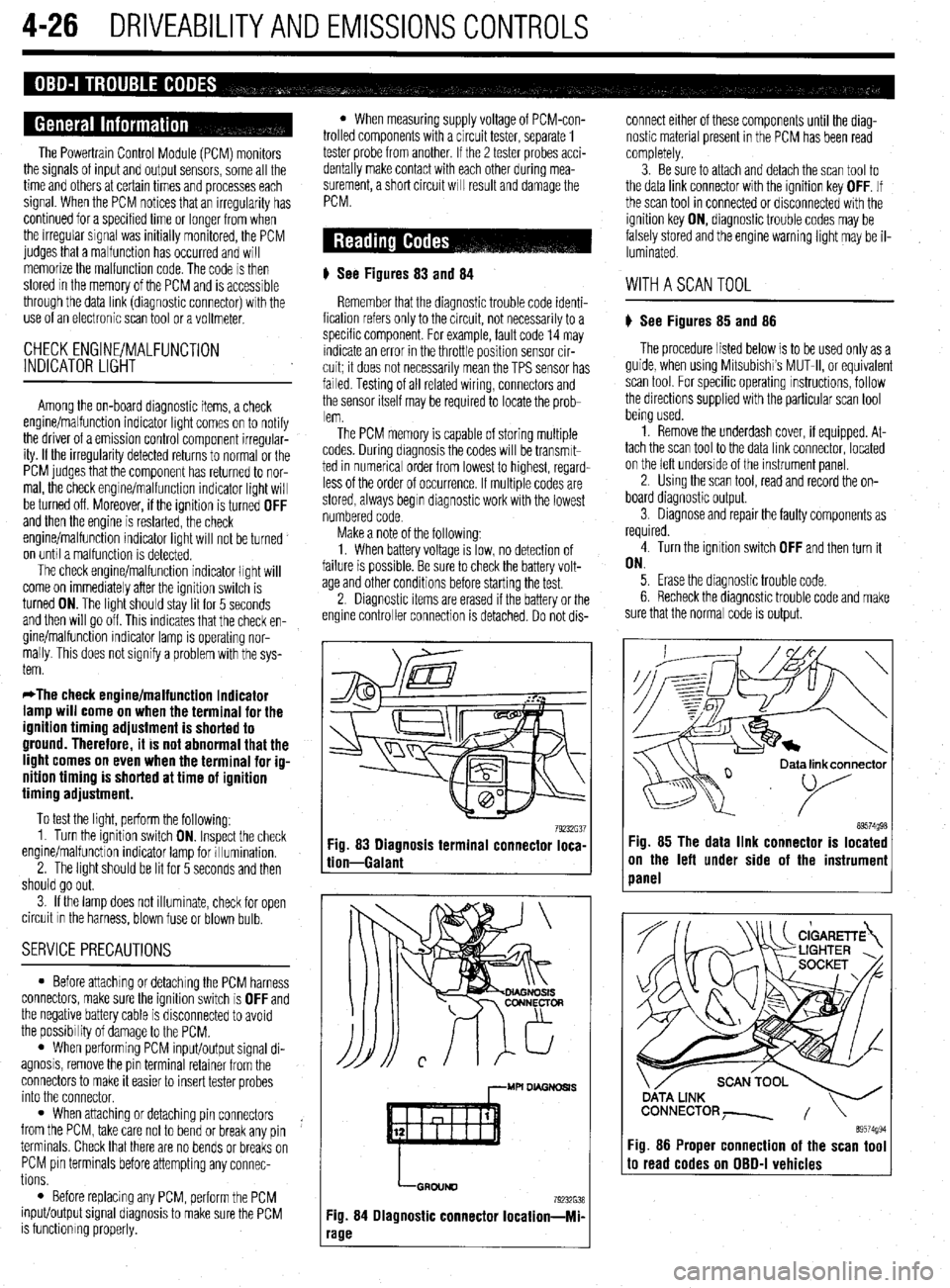
# See Figures 83
and 84
Remember that the diagnostic trouble code identi-
fication refers only to the circuit, not necessarily to a
specific component. For example, fault code 14 may
indicate an error in the throttle position sensor cir-
cuit; it does not necessarily mean the TPS sensor has
failed Testing of all related wiring, connectors and
the sensor itself may be required to locate the prob-
lem.
The PCM memory is capable of storing multiple
codes. During diagnosis the codes will be transmlt-
ted in numerical order from lowest to highest, regard-
less of the order of occurrence. If multiple codes are
stored, always begin diagnostic work with the lowest
numbered code
Make a note of the following:
1. When battery voltage IS low, no detection of
failure is possible. Be sure to check the battery volt-
age and other conditions before starting the test.
2. Diagnostic items are erased if the battery or the
engine controller connection is detached. Do not dis- connect either of these components until the diag-
nostic material present in the PCM has been read
completely.
3. Be sure to attach and detach the scan tool to
the data link connector with the ignition key OFF. If
the scan tool in connected or disconnected with the
ignition key ON, diagnostic trouble codes may be
falsely stored and the engine warning light may be il-
luminated. WITHASCANTOOL
) See Figures 85 and 86
The procedure listed below is to be used only as a
guide, when using Mitsubishi’s MUT-II, or equivalent
scan tool. For specific operating instructions, follow
the directions supplied with the particular scan tool
bemg used.
1. Remove the underdash cover, if equipped. At-
tach the scan tool to the data link connector, located
on the left underside of the instrument panel.
2. Using the scan tool, read and record the on-
board diagnostic output.
3. Diagnose and repair the faulty components as
required
4. Turn the ignition switch OFF and then turn it
ON.
5. Erase the diagnostic trouble code.
6 Recheck the diaanostic trouble code and make
sure that the normal &de is output.
79232G37 89574g98 Fig. 83 Diagnosis terminal connector loca-
tion-Galant Fig. 85 The data link connector is located
on the left under side of the instrumeni
panel
,--MU DL4GNDSl.S
LGRDIJND
79232638
Fig. 84 Diagnostic connector Iocation-Mi-
‘age
ata link connector
89574994 Fig. 86 Proper connection of the scan tool to read codes on OBD-I vehicles
Page 175 of 408
4-32 DRIVEABILITYAND EMISSIONS CONTROLS
PO785 Shift/Timing Solenoid Malfunction
PO786 Shift/Timing Solenoid Range/Performance
PO787 Shift/Timing Solenoid Low
PO788 Shift/Timing Solenord High
PO789 Shift/Timing Solenoid Intermittent
PO790 Normal/Performance Switch Circuit Mal-
function
PO801 Reverse Inhibit Control Circuit Malfunc-
tion
PO803 l-4 Upshift (Skip Shift) Solenoid Control
Circuit Malfunction
PO804 l-4 Upshift (Skip Shift) Lamp Control
Circuit Malfunction
PllOO Induction Control Motor Position Sensor
Fault
PI101 Traction Control Vacuum Solenoid Circuit
Fault
Pl102 Traction Control Ventilation Solenoid Cir-
cuit Fault P1294 Target Idle Speed Not Reached
P1295 No 5-Volt Supply To TP Sensor
P1296 No 5-Volt Supply To MAP Sensor
P1297 No Change In MAP From Start To Run
PI300 Ignition Timing Adjustment Circuit
Pl390 Timing Belt Skipped One Tooth Or More
Pl391 Intermittent Loss Of CMP Or CKP Sensor
Signals P1495 EVAP Ventilation Solenoid Circurt Fault
P1496 5-Volt Supply Output Too Low
Pl500 Generator FR Terminal Circuit Fault
Pl600 PCM-TCM Serial Communication Link
Circuit Fault
Pl400 Manifold Differential Pressure Sensor
Fault P1696 PCM Failure- EEPROM Write Denied
Pl715 No CCD Messages From TCM
Pl750 TCM Pulse Generator Circuit Fault
Pl791 Pressure Control, Shift Control, TCC So-
lenoid Fault
P1443 EVAP Purge Control Solenoid “2” Circuit
Fault P1899 PCM ECT Level Signal to TCM Circuit
Fault
P1486 EVAP Leak Monitor Pinched Hose De-
tected
P1989 High Speed Condenser Fan Control Relay
Fault
P1487 High Speed Radiator Fan Control Relay
Circuit Fault
Pl490 Low Speed Fan Control Relay Fault
P1492 Battery Temperature Sensor High Voltage
P1494 EVAP Ventilation Switch Or Mechanical
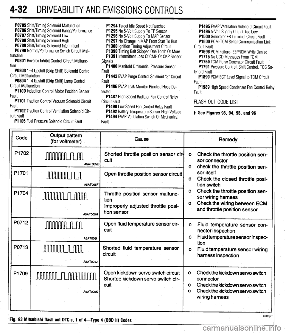
FLASH OUT CODE LIST
# See Figures
93, 94, 95, and 96
Fault PI105 Fuel Pressure Solenoid Circuit Fault
Code
Output pattern
(for voltmeter) Cause
P1702
Shorted throttle position sensor cil
cuit
MATOOSE
Pl701
Open throttle position sensor circuii
A!iATW5F
p1704 -
Throttle position sensor malfunc-
tion
Improperly adjusted throttle posi-
ASATmH tion sensor
PO71 2
Open fluid temperature sensor cir-
u 1 cuit
ASAT
PO71 3
Shorted fluid temperature sensor
circuit
ASATOOU
Pl709
I I Open kickdown servo switch circuit
Shorted kickdown servo switch cir-
cuit
A5ATOOSK
Remedy
o Check the throttle position sen-
sor connector
o check the throttle position sen-
sor itself
o Check the closed throttle posi-
tion switch
o Check the throttle position sen-
sor wiring harness
o Check the wiring between ECM
and throttle position sensor
o Fluid temperature sensor con-
nector inspection
o Fluid temperature sensor inspec-
tion
o Fluid temperature sensor wiring
harness inspection
o Check the kickdown servo switch
connector
o Check the kickdown servo switch
o Checkthe kickdown servo switch
wiring harness
Fig. 93 Mitsubishi flash out DTC's, 1 of 4-Type 4 (DBD II) Codes