1900 MITSUBISHI DIAMANTE wiring
[x] Cancel search: wiringPage 205 of 408
6-2 CHASSIS ELECTRICAL
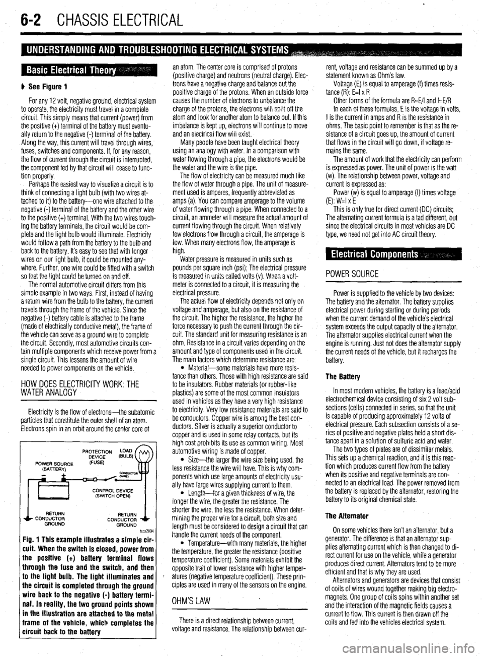
) See Figure 1
For any 12 volt, negative ground, electrical system
to operate, the electricity must travel in a complete
circurt. This simply means that current (power) from
the posibve (t) terminal of the battery must eventu-
ally return to the negative (-) terminal of the battery.
Along the way, this current will travel through wires,
fuses, switches and components. If, for any reason,
the flow of current through the circuit is interrupted,
the component fed by that circuit will cease to func-
tion properly.
Perhaps the easiest way to visualize a circuit is to
think of connecting a light bulb (with two wires at-
tached to it) to the battery-one wire attached to the
negative (-) terminal of the battery and the other wire
to the positive (t) terminal. With the two wires touch-
ing the battery terminals, the circuit would be com-
plete and the light bulb would illummate. Electricity
would follow a path from the battery to the bulb and
back to the battery. It’s easy to see that wrth longer
wires on our light bulb, it could be mounted any-
where. Further, one wire could be fitted with a switch
so that the light could be turned on and off.
The normal automotive circuit differs from this
simple example in two ways, Frrst, instead of having
a return wire from the bulb to the battery, the current
travels through the frame of the vehicle. Since the
negative (-) battery cable is attached to the frame
(made of electrically conductive metal), the frame of
the vehicle can serve as a ground wire to complete
the circuit. Secondly, most automotive circuits con-
tain multiple components which receive power from a
single circuit. This lessens the amount of wire
needed to power components on the vehicle.
HOW DOES ELECTRlClTYWORK:THE
WATER ANALOGY
Electricity is the flow of electrons-the subatomic
particles that constitute the outer shell of an atom.
Electrons spin in an orbit around the center core of
RETURN
RETURN
CONDUCTOR
CONDUCTOR
GROUND
GROUND
lccs2w
Fig. 1 This example illustrates a simple cir-
cuit. When the switch is closed, power from
the positive (t) battery terminal flows
through the fuse and the switch, and then
to the light bulb. The light illuminates and
the circuit is completed through the ground
wire back to the negative (-) battery termi-
nal. In reality, the two ground points shown
in the illustration are attached to the metal
frame of the vehicle, which completes the
circuit back to the battery
an atom The center core is comprised of protons
(positive charge) and neutrons (neutral charge). Elec-
trons have a negative charge and balance
out the
positive charge of the protons. When an outside force
causes the number of electrons to unbalance the
charge of the protons, the electrons will split off the
atom and look for another atom to balance out. If this
imbalance is kept up, electrons will continue to move
and an electrical flow will exist.
Many people have been taught electrical theory
using an analogy with water. In a comparison wrth
water flowing through a pipe, the electrons would be
the water and the wire is the pipe.
The flow of electricity can be measured much like
the flow of water through a pipe. The unit of measure-
ment used is amperes, frequently abbreviated as
amps (a). You can compare amperage to the volume
of water flowing through a pipe. When connected to a
circuit, an ammeter WIII measure the actual amount of
current flowing through the circuit. When relatively
few electrons flow through a circuit, the amperage is
low. When many electrons flow, the amperage is
high.
Water pressure is measured in units such as
pounds per square inch (psi); The electrical pressure
is measured in unrts called volts (v). When a volt-
meter is connected to a circuit, it is measuring the
electrical pressure.
The actual flow of electricity depends not only on
voltage and amperage, but also on the resistance of
the circuit The higher the resistance, the higher the
force necessary to push the current through the cir-
cuit. The standard unit for measuring resistance is an
ohm. Resistance in a crrcuit varies dependmg on the
amount and type of components used in the circuit.
The main factors which determine resistance are:
l Material-some materials have more resis-
tance than others Those with high resistance are said
to be insulators Rubber materials (or rubber-like
plashcs) are some of the most common insulators
used in vehicles as they have a very high resistance
to electricity Very low resistance materials are said to
be conductors. Copper wire is among the best con-
ductors. Silver is actually a superior conductor to
copper and is used in some relay contacts, but its
high cost prohibits its use as common wiring Most
automotive wiring is made of copper.
l Size-the larger the wire size being used, the
less resistance the wire will have. This IS why com-
ponents which use large amounts of electricity usu-
ally have large wires supplying current to them.
l Length-for a given thickness of wire, the
longer the wire, the greater the resistance. The
shorter the wire, the less the resistance. When deter-
mining the proper wire for a circuit, both size and
length must be considered to design a circuit that can
handle the current needs of the component.
l Temperature-with many materials, the higher
the temperature, the greater the resistance (positive
temperature coefficient). Some materials exhibit the
opposite trait of lower resistance with higher temper-
atures (negative temperature coefficient). These prin-
ciples are used in many of the sensors on the engine
OHM'S LAW
There is a direct relationship between current,
voltage and resistance. The relationship between cur- rent, voltage and resistance can be summed up by a
statement known as Ohm’s law.
Voltage (E) is equal to amperage (I) times resis-
tance (R): E=l x R
Other forms of the formula are R=E/I and I=E/R
In each of these formulas, E is the voltage in volts,
I is the current in amps and R IS the resistance in
ohms. The basic point to remember is that as the re-
sistance of a circuit goes up, the amount of current
that flows in the circuit will go down, if voltage re-
mains the same.
The amount of work that the electricity can perform
is expressed as power. The unit of power is the watt
(w). The relationship between power, voltage and
current
IS expressed as:
Power(w) is equal to amperage (I) times voltage
(E): W=l x E
This is only true for direct current (DC) circuits:
The alternating current formula is a tad different, but
since the electrical circuits in most vehicles are DC
type, we need not get into AC circuit theory.
POWERSOURCE
Power is supplied to the vehicle by two devices:
The battery and the alternator. The battery supplies
electrical power during starting or during periods
when the current demand of the vehicle’s electrical
system exceeds the output capacity of the alternator.
The alternator supplies electrical current when the
engine is running
Just not does the alternator supply
the current needs of the vehicle, but it recharges the
battery.
The Battery
In most modern vehicles, the battery is a lead/acid
electrochemical device consisting of six 2 volt sub-
sections (cells) connected in series, so that the unit
is capable of producing approximately 12 volts of
electrical pressure. Each subsection consists of a se-
ries of positive and negative plates held a short dis-
tance apart in a solutron of sulfuric acid and water.
The two types of plates are of dissimilar metals,
This sets up a chemrcal reaction, and it is this reac-
tion which produces current flow from the battery
when Its positive and negattve terminals are con-
nected to an electrical load. The power removed from
the battery is replaced by the alternator, restoring the
battery to its original chemical state.
The Alternator
On some vehicles there isn’t an alternator, but a
generator. The difference IS that an alternator sup-
plies alternating current which is then changed to di-
rect current for
use on the vehicle, while a generator
produces direct current. Alternators tend to be more
efficient and that is why they are used.
Alternators and generators are devices that consist
of coils of wires wound together making big electro-
magnets. One group of coils spins within another set
and the interaction of the magnetic fields causes a
current to flow. This current is then drawn off the
coils and fed into the vehicles electrical system.
Page 206 of 408
CHASSIS ELECTRliAL 6-3
SWITCH
&--; r-- ----
-~~ 85 M
I
-M-L RELAY
SWITCH 86 87
i
---
----w-J
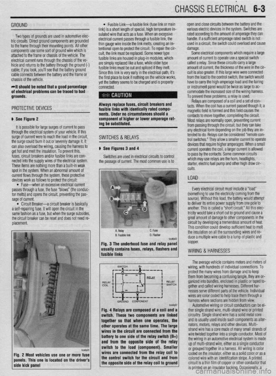
tcca6go2 Fig. 4 Relays are composed of a coil and a
switch. These two components are linked
together so that when one operates, the
other operates at the same time. The large
wires in the circuit are connected from the
battery to one side of the relay switch (B+)
and from the opposite side of the relay
switch to the load (component). Smaller
wires are connected from the relay coil to
the control switch for the circuit and from
the opposite side of the relay coil to ground
The average vehicle contains meters and meters of
wiring, with hundreds of individual connections. To
protect the many wires from damage and to keep
them from becoming a confusing tangle, they are or-
ganized into bundles, enclosed in plastic or taped to-
gether and called wiring harnesses. Different har-
nesses serve different parts of the vehicle. Individual
wires are color coded to help trace them through a
harness where sections are hidden from view.
Automotive wiring or circuit conductors can be ei-
ther single strand wire, multi-strand wire or printed
circuitry. Single strand wire has a solid metal core
and is usually used inside such components as alter-
nators, motors, relays and other devices. Multi-
strand wire has a core made of many small strands of
wire twisted together into a single conductor. Most of
the wiring in an automotive electrical system is made
up of multi-strand wire, either as a single conductor
or grouped together in a harness. All wiring is color
coded on the insulator,,either as a solid color or as a
colored wire with an identification stripe. A printed
circuit is a thin film of copper or other conductor that
is printed on an insulator backing. Occasionally, a
Page 207 of 408
I
6-4 CHASSIS ELECTRICAL
I
printed circuit is sandwiched between two sheets of
plastic for more protection and flexibility. A complete l Weatherproof-these connectors are most the jumper wire is of too small a gauge, it
printed circuit, consisting of conductors, insulating commonly used where the connector is exposed to
may overheat and possibly melt. Never use
material and connectors for lamps or other compo- the elements. Terminals are protected against mois-
nents is called a printed circuit board. Printed cir- ture and dirt by sealing rings which provide a weath- jumpers to bypass high resistance loads in a
et-tight seal. All repairs require the use of a special circuit. Bypassing resistances, in effect, cre-
cuitry is used in place of individual wires or har- ates a short circuit. This may, in turn, cause
nesses in places where space is limited, such as terminal and the tool required to service it. Unlike
behind instrument panels. standard blade type terminals, these weatherproof damage and fire. Jumper wires should only
be used to bypass lengths of wire or to simu-
Since automotive electrical systems are very sen- terminals cannot be straightened once they are bent. late switches.
sitive to changes in resistance, the selection of prop- ‘Make certain that the connectors are properly seated
erly sized wires is critical when systems are repaired, and all of the sealing rings are in place when con-
netting leads. Jumper wires are simple, yet extremely valuable,
A loose or corroded connection or a replacement wire pieces of test equipment. They are basically test wires
that is too small for the circuit will add extra resis-
l Molded-these connectors require complete which are used to bypass sections of a circuit. Al-
replacement of the connector if found to be defective.
tance and an additional voltage drop to the circuit. though jumper wires can be purchased, they are usu-
The wire gauge number is an expression of the This means splicing a new connector assembly into ally fabricated from lengths of standard automotive
cross-section area of the conductor. Vehicles from the harness. All splices should be soldered to insure
proper contact. Use care when probing the connec- wire and whatever type of connector (alligator clip,
countries that use the metric system will typically de- spade connector or pin connector) that is required for
scribe the wire size as its cross-sectional area in tions or replacing terminals in them, as it is possible
square millimeters. In this method, the larger the to create a short circuit between opposite terminals. If the particular application being tested. In cramped,
hard-to-reach areas, it is advisable to have insulated
wire, the greater the number. Another common sys- this happens to the wrong terminal pair, it is possible
to damage certain components. Always use jumper boots over the jumper wire terminals in order to pre-
tern for expressing wire size is the American Wire vent accidental grounding. It is also advisable to in-
Gauge (AWG) system. As gauge number increases, wires between connectors for circuit checking and
NEVER probe through weatherproof seals. elude a standard automotive fuse in any jumper wire.
area decreases and the wire becomes smaller. An 18
gauge wire is smaller than a 4 gauge wire. A wire
l Hard Shell-unlike molded connectors, the This is commonly referred to as a “fused jumper”. By
inserting an in-line fuse holder between a set of test
terminal contacts in hard-shell connectors can be re-
with a higher gauge number will carry less current
placed. Replacement usually involves the use of a leads, a fused jumper wire can be used for bypassing :
than a wire with a lower gauge number. Gauge wire open circuits. Use a 5 amp fuse to provide protection
size refers to the size of the strands of the conductor, special terminal removal tool that depresses the lock- against voltage spikes.
not the size of the complete wire with insulator. It is ing tangs (barbs) on the connector terminal and al-
lows the connector to be removed from the rear of the Jumper wires are used primarily to locate open
possible, therefore, to have two wires of the same
shell. The connector shell should be replaced if it electrical circuits, on either the ground (-) side of the
gauge with different diameters because one may have
thicker insulation than the other. shows any evidence of burning, melting, cracks, or circuit or on the power (+) side. If an electrical corn-
breaks. Replace individual terminals that are burnt, ponent fails to operate, connect the jumper wire be-
It is essential to understand how a circuit works
corroded, distorted or loose. tween the component and a good ground. If the corn-
before trying to figure out why it doesn’t. An electrical ponent operates only with the jumper installed, the
schematic shows the electrical current paths when a ground circuit is open. If the ground circuit is good,
circuit is operating properly. Schematics break the but the component does not operate, the circuit be-
entire electrical system down into individual circuits. tween the power feed and component may be open. ’
In a schematic, usually no attempt is made to repre- Pinpointing the exact cause of trouble in an elec- By moving the jumper wire successively back from
trical circuit is most times accomplished by the use the component toward the power source, you can
; : sent wiring and components as they physically ap-
pear on the vehicle; switches and other components of special test equipment. The following describes isolate the area of the circuit where the open is lo-
are shown as simply as possible. Face views of har- different types of commonly used test equipment and cated. When the component stops functioning, or the f
j
ness connectors show the cavity or terminal locations briefly explains how to use them in diagnosis. In ad- power is cut off, the open is in the segment of wire j
in all multi-pin connectors to help locate test points. dition to the information covered below, the tool between the jumper and the point previously tested.
! manufacturer’s instructions booklet (provided with You can sometimes connect the jumper wire di-
the tester) should be read and clearly under.$ood be- rectly from the battery to the “hot” terminal of the I
CONNECTORS 1 fore attempting any test procedures. component, but first make sure the component uses 1
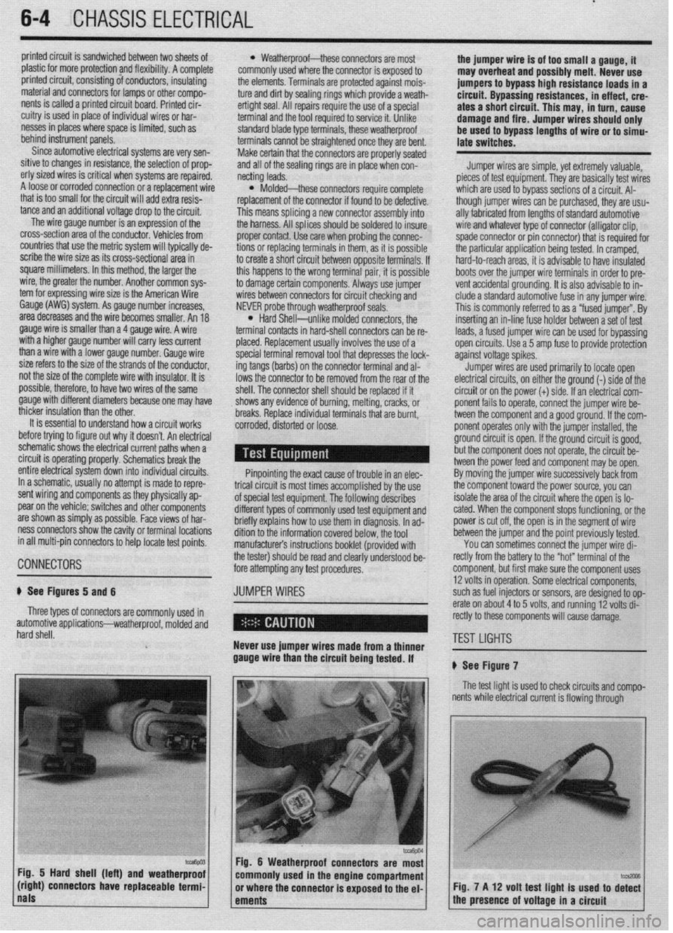
# See Figures 5 and 6 JUMPER WIRES 12 volts in operation. Some electrical components, i
such as fuel injectors or sensors, are designed to op-
Three types of connectors are commonly used in erate on about 4 to 5 volts, and running 12 volts di- j
)
automotive applications-weatherproof, molded and rectly to these components will cause damage.
hard shell.
Never use jumper wires made from a thinner TEST LIGHTS I
gauge wire than the circuit being tested. If
# See Figure 7
The test light is used to check circuits and compo-
I nents while electrical current is flowing through
Fig. 5 Hard shell (left) and weatherproof
(right) connectors have replaceable termi- Fig. 7 A 12 volt test light is used to di%
nals
ements 1 the presence of voltage in a circuit
Page 208 of 408
CHASSIS ELECTRiCAL 6-5
them. It is used for voltage and ground tests. To use voltmeter has a positive and a negative lead. To avoid
a 12 volt test light, connect the ground clip to a good damage to the meter, always connect the negative
ground and probe wherever necessary with the pick. lead to the negative (-) side of the circuit (to ground
The test light will illuminate when voltage is detected. or nearest the ground side of the circuit) and connect
This
does not necessarily mean that 12 volts (or any the positive lead to the positive(t) side of the circuit When diagnosing a specific problem, organized
troubleshooting is a must. The complexity of a mod-
particular amount of voltage) is present; it only (to the power source or the nearest power source).
means that some voltage is present. It is advisable Note that the negative voltmeter lead will always be ern automotive vehicle demands that you approach
before using the test light to touch its ground clip black and that the positive voltmeter will always be any problem in a logical, organized manner. There
and probe across the battery posts or terminals to some color other than black (usually red). are certain troubleshooting techniques, however,
which are standard:
make sure the light is operating properly.
l Ohmmeter-the ohmmeter is designed to read l Establish when the problem occurs. Does the
resistance (measured in ohms) in a circuit or compo-
nent. Most ohmmeters will have a selector switch problem appear only under certain conditions? Were
there any noises, odors or other unusual symptoms?
Do not use a test light to probe electronic ig- which permits the measurement of different ranges of
Isolate the problem area. To do this, make some sim-
nition, spark plug or coil wires. Never use a resistance (usually the selector switch allows the
multiplication of the meter reading by 10,100,1,000 ple tests and observations, then eliminate the sys-
pick-type test light to probe wiring on com- terns that are working properly. Check for obvious
puter controlled systems unless specifically and 10,000). Some ohmmeters are “auto-ranging”
which means the meter itself will determine which problems, such as broken wires and loose or dirty
instructed to do so. Any wire insulation that
scale to use. Since the meters are powered by an in- connections. Always check the obvious before as-
is pierced by the test light probe should be
ternal battery, the ohmmeter can be used like a self- suming something complicated is the cause.
taped and sealed with silicone after testing.
l Test for problems systematically to determine
powered test light. When the ohmmeter is connected,
the cause once the problem area is isolated. Are all
Like the jumper wire, the 12 volt test light is used current from the ohmmeter flows through the circuit
the components functioning properly? Is there power
to isolate opens in circuits. But, whereas the jumper or component being tested. Since the ohmmeter’s in-
ternal resistance and voltage are known values, the going to electrical switches and motors. Performing
wire is used to bypass the open to operate the load,
amount of current flow through the meter depends on careful, systematic checks will often turn up most
the 12 volt test light is used to locate the presence of
the resistance of the circuit or component being causes on the first inspection, without wasting time
voltage in a circuit. If the test light illuminates, there
tested. The ohmmeter can also be used to perform a checking components that have little or no relation-
is power up to that point in the circuit; if the test light ship to the problem.
does not illuminate, there is an open circuit (no continuity test for suspected open circuits. In using
the meter for making continuity checks, do not be
l Test all repairs after the work is done to make
power). Move the test light in successive steps back
concerned with the
actual resistance readings. Zero sure that the problem is fixed. Some causes can be
toward the power source until the light in the handle traced to more than one component, so a careful veri-
illuminates. The open is between the probe and a resistance, or any ohm reading, indicates continuity
fication of repair work is important in order to pick up
point which was previously probed. in the circuit, Infinite resistance indicates an opening
in the circuit. A high resistance reading where there additional malfunctions that may cause a problem to
The self-powered test light is similar in design to
should be none indicates a problem in the circuit. reappear or a different problem to arise. A blown
the 12 volt test light, but contains a 1.5 volt penlight
Checks for short circuits are made in the same man- fuse, for example, is a simple problem that may re-
battery in the handle. It is most often used in place of
ner as checks for open circuits, except that the circuit quire more than another fuse to repair. If you don’t
a multimeter to check for open or short circuits when look for a problem that caused a fuse to blow, a
power is isolated from the circuit (continuity test). must be isolated from both power and normal
ground. Infinite resistance indicates no continuity, shorted wire (for example) may go undetected.
The battery in a self-powered test light does not Experience has shown that most problems tend
provide much current. A weak battery may not pro- while zero resistance indicates a dead short.
to be the result of a fairly simple and obvious
vide enough power to illuminate the test light even I ’ cause, such as loose or corroded connectors, bad
when a complete circuit is made (especially if there is grounds or damaged wire insulation which causes a
high resistance in the circuit). Always make sure that Never use an ohmmeter to check the resis- short. This makes careful visual inspection of com-
the test battery is strong. To check the battery, briefly tance of a component or wire while there is ponents during testing essential to quick and accu-
touch the ground clip to the probe; if the light glows voltage applied to the circuit. rate troubleshooting.
brightly, the battery is strong enough for testing.
*A self-powered test light should not be
l Ammeter-an ammeter measures the amount
- I
used on any computer controlled system or of current flowing through a circuit in units called
component. The small amount of electricity amperes or amps. At normal operating voltage, most
circuits have a characteristic amount of amperes, OPEN CIRCUITS
transmitted by the test light is enough to
damage many electronic automotive compo- called “current draw” which can be measured using
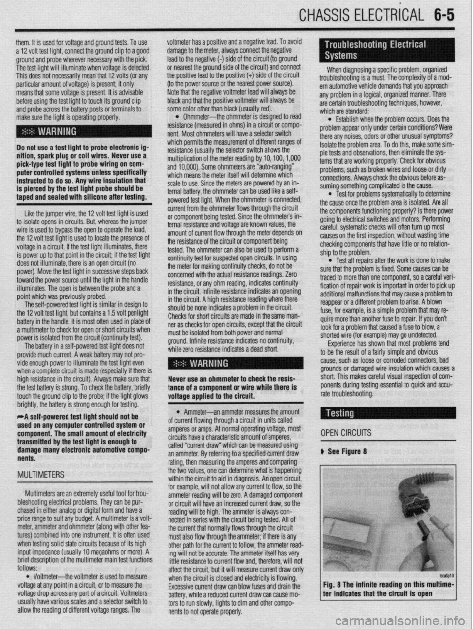
an ammeter. By referring to a specified current draw # See Figure 8
nents.
rating, then measuring the amperes and comparing
MULTIMETERS the two values, one can determine what is happening
within the circuit to aid in diagnosis. An open circuit,
for example, will not allow any current to flow, so the
Multimeters are an extremely useful tool for trou-
bleshooting electrical problems. They can be pur- ammeter reading will be zero. A damaged component
or circuit will have an increased current draw, so the
chased in either analog or digital form and have a
reading will be high. The ammeter is always con-
price range to suit any budget. A multimeter is a volt-
netted in series with the circuit being tested. All of
meter, ammeter and ohmmeter (along with other fea-
the current that normally flows through the circuit
tures) combined into one instrument. It is often used
must also flow through the ammeter; if there is any
when testing solid state circuits because of its high
other path for the current to follow, the ammeter read-
input impedance (usually 10 megaohms or more). A
ing will not be accurate. The ammeter itself has very
brief description of the multiieter main test functions
follows: little resistance to current flow and, therefore, will not
affect the circuit, but it will measure current draw only
l Voltmeter--the voltmeter is used to measure
when the circuit is closed and electricity is flowing.
voltage at any point in a circuit, or to measure the
Excessive current draw can blow fuses and drain the
voltage drop across any part of a circuit. Voltmeters
battery, while a reduced current draw can cause mo-
usually have various scales and a selector switch to
tors to run slowly, lights to dim and other compo-
allow the reading of different voltage ranges. The
nents to not operate properly.
Page 213 of 408
640 CHASSIS ELECTRICAL
careful not to allow anything to come in contact with
the air bag unit.
16. Remove the glove box lamp assembly.
17. Remove the remaining instrument panel
mounting screws and remove the instrument panel
from the vehicle.
18. Remove the left side foot shower ductwork,
lap cooler duct and center duct.
19. Remove the front and center reinforcements
and center stay assembly.
20. Remove the air distribution duct assembly.
21. Detach all connectors from heater-box-
mounted items.
22. Remove the heater box mounting screws and
nut, then remove the unit from the vehicle.
23. Disassemble on a workbench. Remove the
heater core from the heater case.
To install:
24. Thoroughly clean and dry the inside of the
case and install the heater core and all related parts.
25. Install the heater unit to the vehicle and install
the mounting screws and nut. Be sure the evaporator
case and heater case are fitted together properly. At-
tach all connectors to heater-box-mounted items.
26. Install the air distribution duct assembly. In-
stall the front and center reinforcements and center
stay assembly.
27. Install the center duct, lap cooler duct and left
side foot shower duct.
28. Install the instrument panel and mounting
screws.
29. Install the glove box lamp assembly.
30. Secure the steering column and attach all
steering column connectors.
31. Install the speedometer cable adapter to the
instrument panel.
32. Install the instrument cluster and the instru-
ment cluster bezel.
33. Install the speakers to the top of the instru-
ment panel.
34. Install the cup holder.
35. Install the climate control system control
head.
36. Install the stereo entertainment system and
bezel.
37. Install the screw below the glove box assem-
bly, and the entire glove box unit.
38. Install the steering column covers.
39. Install the knee protector support bracket, the
protector and the decorative plugs.
40. Install the console and the ashtray. 41. Install the right side foot shower duct.
42. Install the passenger side undercover.
43. Connect the heater hoses to the core tubes.
44. Fill the cooling system.
45. Connect the negative battery cable and check
the entire climate control system for proper operation
and leaks.
Galant
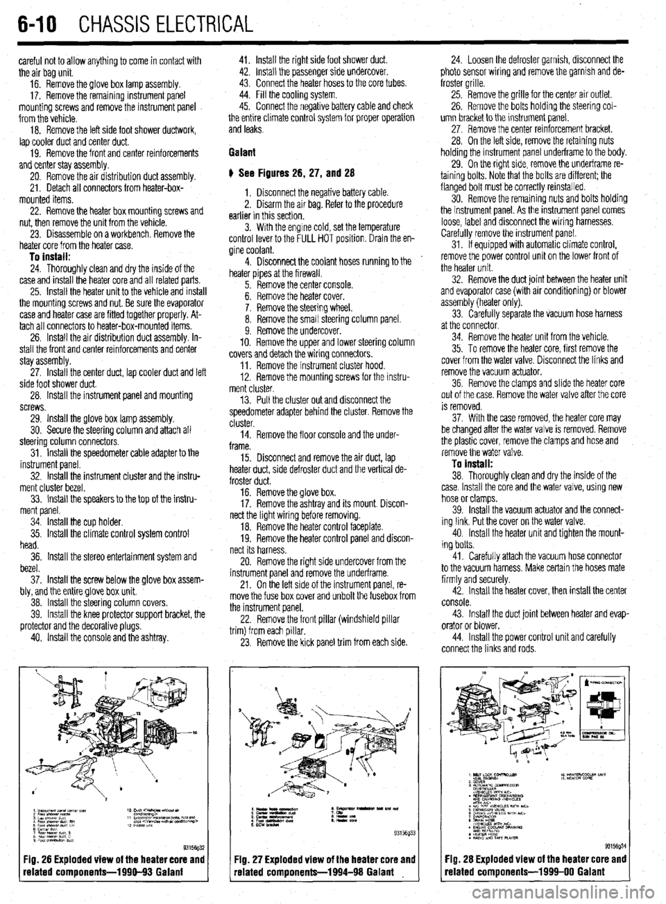
# See Figures 26, 27, and 28
1. Disconnect the negative battery cable.
2. Disarm the air bag. Refer to the procedure
earlier in this section.
3. With the engine cold, set the temperature
control lever to the FULL HOT position. Drain the en-
gine coolant.
4. Disconnect the coolant hoses running to the
heater pipes at the firewall.
5. Remove the center console.
6. Remove the heater cover.
7. Remove the steering wheel.
8. Remove the small steering column panel.
9. Remove the undercover.
10. Remove the upper and lower steering column
covers and detach the wiring connectors.
11. Remove the instrument cluster hood.
12. Remove the mounting screws for the instru-
ment cluster.
13. Pull the cluster out and disconnect the
speedometer adapter behind the cluster. Remove the
cluster.
14. Remove the floor console and the under-
frame.
15. Disconnect and remove the air duct, lap
heater duct, side defroster duct and the vertical de-
froster duct.
16. Remove the glove box.
17. Remove the ashtray and its mount. Discon-
nect the light wiring before removing.
18. Remove the heater control faceplate.
19. Remove the heater control panel and discon-
nect its harness.
20. Remove the right side undercover from the
instrument panel and remove the underframe.
21. On the left side of the instrument panel, re-
move the fuse box cover and unbolt the fusebox from
the instrument panel.
22. Remove the front pillar (windshield pillar
trim) from each pillar.
23. Remove the kick panel trim from each side.
Fig. 26 Exploded view of the heater core and
related components-1990-93 Galant
:IQ. 27 Exploded view of the heater core and
-elated components-1994-98 Galant 24. Loosen the defroster garnish, disconnect the
photo sensor wiring and remove the garnish and de-
froster grille.
25. Remove the grille for the center air outlet.
26. Remove the bolts holding the steering col-
umn bracket to the instrument panel.
27, Remove the center reinforcement bracket.
28. On the left side, remove the retaining nuts
holding the instrument panel underframe to the body.
29. On the right side, remove the underframe re-
taining bolts. Note that the bolts are different; the
flanged bolt must be correctly reinstalled.
30. Remove the remaining nuts and bolts holding
the instrument panel. As the instrument panel comes
loose, label and disconnect the wiring harnesses.
Carefully remove the instrument panel.
31. If equipped with automatic climate control,
remove the power control unit on the lower front of
the heater unit.
32. Remove the duct joint between the heater unit
and evaporator case (with air conditioning) or blower
assembly (heater only).
33. Carefully separate the vacuum hose harness
at the connector.
34. Remove the heater unit from the vehicle.
35. To remove the heater core, first remove the
cover from the water valve. Disconnect the links and
remove the vacuum actuator.
36. Remove the clamps and slide the heater core
out of the case. Remove the water valve after the core
is removed.
37. With the case removed, the heater core may
be changed after the water valve is removed. Remove
the plastic cover, remove the clamps and hose and
remove the water valve.
To install:
38. Thoroughly clean and dry the inside of the
case. Install the core and the water valve, using new
hose or clamps.
39. Install the vacuum actuator and the connect-
ing link. Put the cover on the water valve.
40. Install the heater unit and tighten the mount-
ing bolts.
41. Carefully attach the vacuum hose connector
to the vacuum harness. Make certain the hoses mate
firmly and securely.
42. Install the heater cover, then install the center
console.
43. Install the duct joint between heater and evap-
orator or blower.
44. Install the power control unit and carefully
connect the links and rods.
Fig. 28 Exploded view of the heater core and
related components-1999-00 Galant
Page 214 of 408
CHASSIS ELECTRICAL 6-11
45. Install the heater hoses under the hood.
46. Install the mstrument panel by reversing its
removal procedure.
47. Install the center console.
48. install the upper and lower steering column
covers.
49. Install the center panel undercover.
50. Install the small column panel.
51. Install the steering wheel.
52. Fill the cooling system.
53. Connect the negative battery cable and check
the entire climate control system for proper operation
and leaks.
Mirage
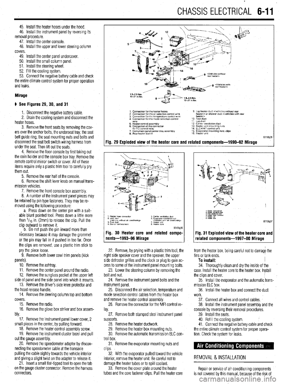
# See Figures 29, 30, and 31
1. Disconnect the negative battery cable.
2. Drain the cooling system and disconnect the
heater hoses.
3. Remove the front seats by removing the cov-
ers over the anchor bolts, the underseat tray, the seat
belt guide ring, the seat mounting nuts and bolts and
disconnect the seat belt switch wiring harness from
under the seat. Then lift out the seats
4. Remove the floor console by first taking out
the coin holder and the console box tray. Remove the
remote control mirror switch or cover. All of these
items require only a plastic trim tool to carefully pry
them out.
5. Remove the rear half of the console.
6. Remove the shift lever knob on manual trans-
mission vehicles.
7. Remove the front console box assembly.
8. A number of the instrument panel pieces may
be retamed by pin type fasteners. They may be re-
moved using the following procedure:
a. Press down on the center pin with a suit-
able blunt pointed tool. Press down a little more
than l/re in. (2mm) to release the clip. Pull the
clip outward to remove it.
b. Do not oush the oin inward more than
necessary because it may damage the grommet
or the pin may fall in if pushed in too far. Once
the clips are removed, use a plastic trim stick to
pry the piece loose.
9. Remove both lower cowl trim panels (kick
panels).
10. Remove the ashtray.
11. Remove the center panel around the radio.
12. Remove the sunglass pocket at the upper left
side of panel and the side panel into which it mounts,
13. Remove the drivers side knee protector and
the hood release handle.
14. Remove the steering column top and bottom
covers.
15. Remove the radio.
16. Remove the glove box striker and box assem-
bly.
17. Remove the instrument panel lower cover, 2
small pieces in the center, by pulling forward.
18. Remove the heater control assembly screw.
19. Remove the instrument cluster bezel and pull
out the Qauge assembly.
20. Remove the speedometer adapter by discon-
necting the speedometer cable at the transaxle
pulling the cable Sightly towards the vehicle interior
and giving a Slight twist on the adapter to release it.
21. Insert a small flat-tipped tool to open the tab
on the QauQe cluster connector. Remove the harness
connectors.
Fig. 29 Exploded view of the heater core and related components-1990-92 Mirage
93l%Q% Fig. 30 Heater core and related compo-
nents-1993-96 Mirage
22. Remove, by prying with a plastic trim tool, the
right side speaker cover and the speaker, the upper
side defroster grilles and the clock or plug to gain ac-
cess to some of the instrument panel mounting bolts.
23. Lower the steering column by removing the
bolt and nut.
24. Remove the instrument panel bolts and the
instrument panel.
25 Drsconnect the air selection, temperature and
mode selection control cables from the heater box
and remove the heater control assembly.
26. Remove the connector for the MFI control re-
lay.
27. Remove both stamped steel instrument panel
supports.
28. Remove the heater ductwork.
29. Remove the heater box mounting nuts.
30 Remove the automatic transmission ELC con-
trol box.
31. Remove the evaporator mounting nuts and
clips.
32. With the evaporator pulled toward the vehicle
interior, remove the heater unit. Be careful not to
damage the heater tubes or to spill coolant.
33. Remove the cover plate around the heater
tubes and the core fastener clips. Pull the heater core 34. Thoroughly clean and dry the inside of the
case. Install the heater core to the heater box. Install
the clips and cover,
35. Install the evaporator and the automatic trans-
mission ELC box.
36. Install the heater box and connect the duct
Fig. 31 Exploded view of the heater core and
related components-1997-00 Mirage
from the heater box, being careful not to damage the
fins or tank ends.
To install: I
work.
37. Connect all wires and control cables,
38. Install the instrument panel assembly and the
console by reversmg their removal procedures.
39 Install the seats.
40. Refill the cooling system.
41. Connect the negative battery cable and check
the entire climate control system for proper opera-
tion Check the system for leaks.
REMOVAL &INSTALLATION
Repair or service of air Conditioning components
is not covered by this manual, because of the risk of
Page 217 of 408
6-14 CHASSIS ELECTRICAL
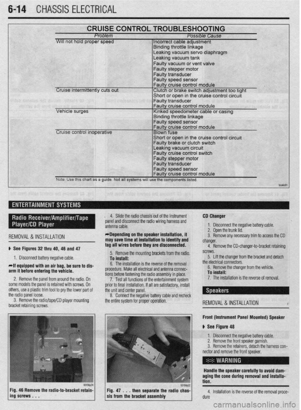
CRUISE CONTROL TROUBLESHOOTING Problem Posable Cause
WIII not hold proper speed 1 Incorrect cable adjustment
F.~. _I.~_ - 1L .-AL‘- I. I -
Cruise intermittently cuts out
trrnarng Inrome nnKage Leaking vacuum servo diaphragm
Leaking vacuum tank
Faulty vacuum or vent valve
Faulty stepper motor
Faulty transducer
Faulty speed sensor
Faulty cruise control module
‘ Clutch or brake switch adjustment too tight -chnrt *r nna* in the cruise control circuit
cer VI I”, . vt “y”‘,
I- Faulty transdu
Leaking vacuum circuit Faulty cruise control switch
Faulty stepper motor
Note. Use this chart as a guide. Not all systems will use the components listed.
t-,
I ,-- ,
REMOVAL&INSTALLATION
# See Figures 32 thru 40, 46 and 47
1. Disconnect battery negative cable.
*If equipped with an air bag, be sure to dis-
arm it before entering the vehicle.
2. Remove the panel from around the radio, On
some models the panel is retained with screws, On
others, use a plastic trim tool to pry the lower pad of
the radio panel loose.
3. Remove the radio/tape/CD player mounting
bracket retaining screws, 4. Slide the radio chassis out of the instrument
*panel and disconnect the radio wiring harness and
*Depending on the speaker installation, it
may save time at installation to identify and
tag all wires before they are disconnected.
5. Remove the mounting brackets from the radio.
To install:
6. The installation is the reverse of the removal
procedure. Make all electrical and antenna connec-
tions before fastening the radio assembly in place.
7. Test all functions of the entertainment system
prior to final installation. If all are satisfactory, install
the unit and center panel.
8. Connect the negative battery cable and recheck
the entire system for proper operation. CD Changer
1. Disconnect the negative battery cable.
2. Open the trunk lid.
3. Remove any necessary trim to access the CD
changer.
4. Remove the CD-changer-to-bracket retaining
screws.
5. Lift the changer from the bracket and detach
the electrical connectors.
6. Remove the changer from the vehicle.
To install:
7. The installation is the reverse of removal.
REMOVAL&INSTALLATION l
Front (Instrument Panel Mounted) Speaker
u See Figure 48
1. Disconnect the negative battery cable.
2. Remove the front speaker garnish.
3. Remove the retainers, detach the harness con-
nector and remove the front speaker,
Handle the speaker carefully to avoid dam-
aging the cone during removal and installa-
tion.
4. Installation is the reverse of the removal proce-
dure
Page 230 of 408
CHASSIS ELECTRICAL 6-27
1. Remove the fuse box cover.
2. lnsoect the fuses to determine which is faulty.
REPLACEMENT 3. Grasp the fuse and remove it from the fuse
box. Never exceed the amperage rating of a blown
4. Inspect the box terminals and clean if cor- fuse. If the replacement fuse also blows,
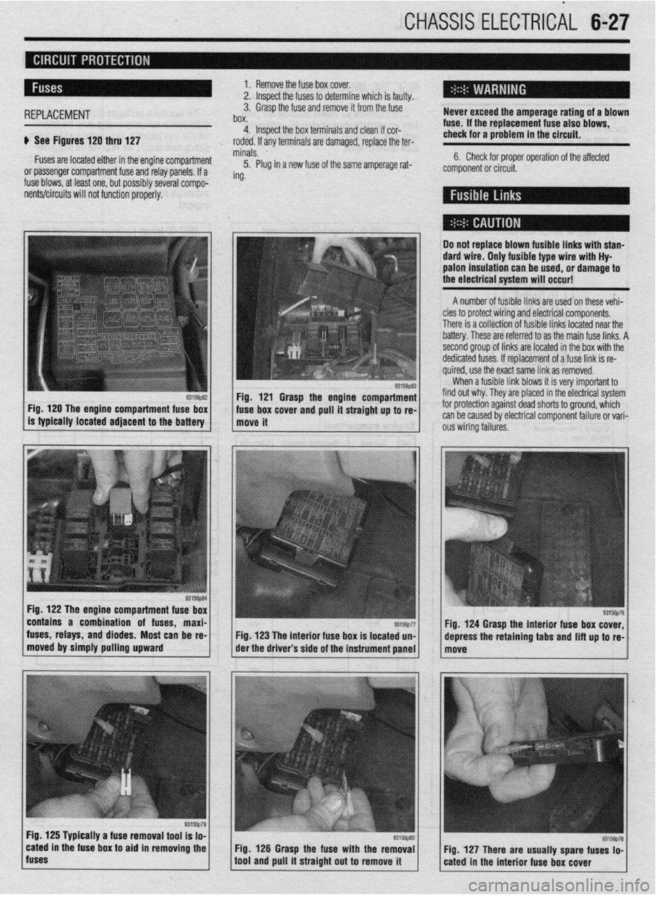
It See Figures 120 thru 127 check for a problem in the circuit.
roded. If any terminals are damaged, replace the ter-
Fuses are located either in the engine Compartment minals. ’
5. Plug in a new fuse of the same amperage rat- 6. Check for proper operation of the affected
or passenger compartment fuse and relay panels. If a component or circuit.
fuse blows, at least one, but possibly several compo- ing.
ients/circuits will not function properly.
Fig, 120 The engine compartment fuse box
is typically located adjacent to the
battery
Fig. 122 The engine compartment fuse box
contains a combination of fuses, maxi-
fuses, relays, and diodes. Most can be re-
moved by simply pulling upward
I Do not replace blown fusible links with stan-
dard wire. Only fusible type wire with Hy
palon insulation can be
used, or damage to
the electrical system will occur!
A number of fusible links are used on these vehi-
cles to protect wiring and electrical components.
There is a collection of fusible links located near the
battery. These are referred to as the main fuse links. A
second group of links are located in the box with the
dedicated fuses. If replacement of a fuse link is re-
quired, use the exact same link as removed.
When a fusible link blows it is very important to
Fig. 121 Grasp the engine compartment find out why. They are placed in the electrical system
. ’ ‘“‘,+“” 1 ous wiring failures. fuse box cover and pull It straight up to re- for protection against dead shorts to ground, which
move it can be caused by electrical component failure or vari-
Fig. 123 The interior fuse box is located un-
der the driver’s side of the instrument panel
Fig. 125 Typically a fuse removal tool is lo-
cated in the fuse box to aid in removing the
fuses Fig. 126 Grasp the fuse with the removal
tool and pull it straight out to remove it Fig. 124 Grasp the interior fuse box cover,
depress the retaining
tabs and lift up to re-