1900 MITSUBISHI DIAMANTE wiring
[x] Cancel search: wiringPage 176 of 408
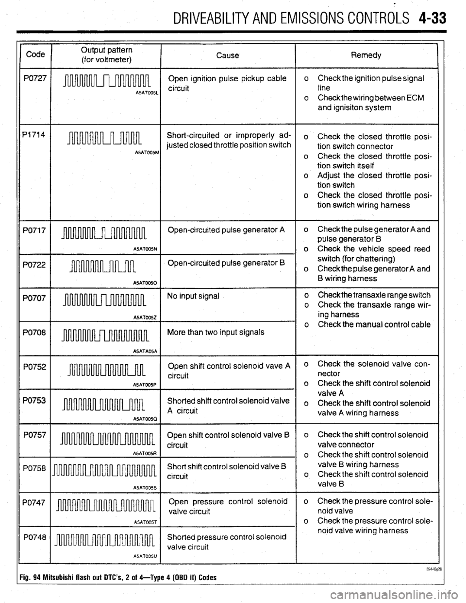
DRIVEABILITYAND EMISSIONS CONTROLS 4-33
Code
PO727
P1714
PO71 7
PO722
PO707
PO708
PO752
PO753
PO757
PO758
PO747
PO748 Output pattern
(for voltmeter) Cause Remedy
A5ATW51
Open ignition pulse pickup cable
circuit o Check the ignition pulse signal
line
o Checkthe wiring between ECM
and ignisiton system
Short-circuited or improperly ad-
o Check the closed throttle posi-
justed closed throttle position switch
tion switch connector
ASATOOSM o Check the closed throttle posi-
tion switch itself
o Adjust the closed throttle posi-
tion switch
o Check the closed throttle posi-
tion switch wiring harness
Open-circuited pulse generator A o Check the pulse generator A and
pulse generator 6
ASATOOSN o Check the vehicle speed reed
Open-circuited pulse generator B switch (for chattering)
o CheckthepulsegeneratorA and
A5ATOO50 B wiring harness
m No input signal o Checkthe transaxle range switch
o Check the transaxle range wir-
A5ATOO.52 ing harness
o Check the manual control cable
ASATOOSP
ASATOO5Q
A5ATOOSS
I Open shift control solenoid vave A
circuit
Shorted shift control solenoid valve
Open shift control solenoid valve B
Short shift control solenoid valve B
circuit o Check the solenoid valve con-
nector
o Check the shift control solenoid
valve A
o Check the shift control solenoid
valve A wiring harness
o Check the shift control solenoid
valve connector
o Check the shift control solenoid
valve B wiring harness
o Check the shift control solenoid
valve B
Open pressure control solenoid
valve circuit o Check the pressure control sole-
noid valve
o Check the pressure control sole-
noid valve wiring harness
ASATOOSJ
I
89446928
i9. 94 Mitsubishi flash out DTC’s, 2 of 4-Type 4 (DBD II) Codes
Page 177 of 408
.
4-34 DRIVEABILITYAND EMISSIONS CONTROLS
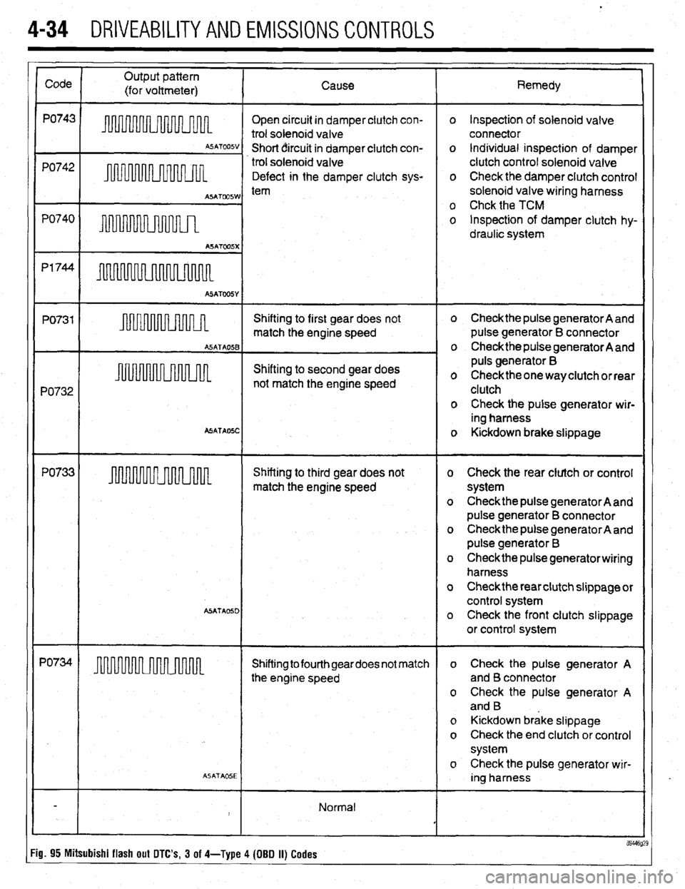
Open circuit in damper clutch con-
trol solenoid valve
Short circuit in damper clutch con-
trol solenoid valve
Defect in the damper clutch sys- o Inspection of solenoid valve
connector
o Individual inspection of damper
clutch control solenoid valve
o Check the damper clutch control
solenoid valve wiring harness
o Chck the TCM
o Inspection of damper clutch hy-
draulic system
PO732 Shifting to first gear does not heckthe pulse generator A and
match the engine speed pulse generator B connector
o Check the pulse generator A and
Shifting to second gear does puls generator B
not match the engine speed o Checkthe one way clutch or rear
clutch
o Check the pulse generator wir-
ing harness
ASATAOSC o Kickdown brake slippage
PO733 Shifting to third gear does not o Check the rear clutch or control
match the engine speed system
o Check the pulse generator A and
pulse generator B connector
o Check the pulse generator A and
pulse generator B
o Checkthe pulse generatorwiring
harness
o Check the rear clutch slippage or
control system
A5ATA05D o Check the front clutch slippage
or control system
PO734
Shifting to fourth geardoes not match o Check the pulse generator A
the engine speed and B connector
o Check the pulse generator A
and B
o Kickdown brake slippage
o Check the end clutch or control
system
o Check the pulse generator wir-
ASATA05E ing harness
Normal
J
89446 :ig. 95 Mitsubishi flash out DTC’s, 3 of 4-Type 4 (OBD II) Codes
Page 190 of 408
FUELSYSTEM 513
l Always replace worn fuel fitting O-rings with
new. Do not substitute fuel hose or equivalent, where
I
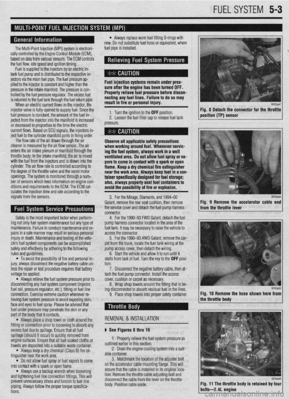
The Multi-Point Injection (MPI) system is electroni-
rally controlled by the Engine Control Module (ECM),
based on data from various sensors. The ECM controls
the fuel flow, idle speed and ignition timing. fuel pipe is installed.
Fuel is supplied to the injectors by an electric in-
tank fuel pump and is distributed to the respective in-
jectors via the main fuel pipe. The fuel pressure ap-
plied to the injector is constant and higher than the
pressure in the intake manifold. The pressure is con-
trolled by the fuel pressure regulator. The excess fuel
is returned to the fuel tank through the fuel return pipe.
When an electric current flows in the injector, the
injector valve is fully opened to supply fuel. Since the
fuel pressure is constant, the amount of the fuel in-
jetted from the injector into the manifold is increased
or decreased in proportion to the time the electric
current flows. Based on ECU signals, the injectors in-
ject fuel to the cylinder manifold ports in firing order. Fuel injection systems remain under pres-
sure after the engine has been turned OFF.
Properly relieve fuel pressure before discon-
neeting any fuel lines. Failure to do so may
result in fire or personal injury.
1. Turn the ignition to the OFF position.
2. Loosen the fuel filler cap to release fuel tank
pressure.
I
The flow rate of the air drawn through the air
cleaner is measured by the air flow sensor. The air
enters the air intake plenum or manifold through the
throttle body. In the intake manifold, the air is mixed
with the fuel from the injectors and is drawn into the
cylinder, The air flow rate is controlled according to
the degree of the throttle valve and the servo motor
openings. The system is monitored through a num-
ber of sensors which feed information on engine con-
ditions and requirements to the ECM. The ECM cal-
culates the injection time and rate according to the
signals from the sensors,
Safety is the most important factor when perform-
ing not only fuel system maintenance but any type of
maintenance. Failure to conduct maintenance and re-
pairs in a safe manner may result in serious personal
injury or death. Maintenance and testing of the vehi-
cle’s fuel system components can be accomplished
safely and effectively by adhering to the following
rules and guidelines.
l To avoid the possibility of fire and personal in-
jury, always disconnect the negative battery cable un-
less the repair or test procedure requires that battery
voltage be applied.
l Always relieve the fuel system pressure prior to
disconnecting any fuel system component (injector,
fuel rail, pressure regulator, etc.), fitting or fuel line
connection. Exercise extreme caution whenever re- Observe all applicable safety precautions
when working around fuel. Whenever servic-
ing the fuel system, always work in a well
ventilated area. Do not allow fuel spray or va-
pors to come in contact with a spark or open
flame. Keep a dry chemical fire extinguisher
near the work area. Always keep fuel in a con-
tainer specifically designed for fuel storage;
also, always properly seal fuel containers to
avoid the possibility of fire or explosion.
3. For the Mirage, Diamante, and 1994-00
Galant, remove the rear seat cushion, then remove
the service cover and detach the fuel pump harness
connector.
4. For the 1990-93 FWD Galant, detach the fuel
pump harness connector located in the area of the
fuel tank. It may be necessary to raise the vehicle to
access the connector.
5. For the 1990-93 AWD Galant, remove the car-
pet from the trunk, locate the fuel tank wiring at the
pump access cover, then detach the wiring.
6. Start the vehicle and allow it to run until it
stalls from lack of fuel. Turn the key to the OFF posi-
tion.
7. Disconnect the negative battery cable, then at-
tach the fuel pump connector. Install the access .
cover, cushion or carpet as necessary.
8. Wrap shop towels around the fitting that is be-
ing disconnected to absorb residual fuel in the lines.
9. Place shop towels into proper safety container. Fig, 8 Detach the connector for the throttle
position (TP) sensor
93153ps5 Fig, 9 Remove the accelerator cable end
from the throttle lever
Fig. IO Remove the hose shown here from
lieving fuel system pressure to avoid exposing skin,
face and eyes to fuel spray. Please be advised that
fuel under pressure may penetrate the skin or any
part of the body that it contacts.
l Always place a shop towel or cloth around the
fitting or connection prior to loosening to absorb any
excess fuel due to spillage. Ensure that all fuel
spillage (should it occur) is quickly removed from
enginesurfaces. Ensure that all fuel soaked cloths or
towels are deposited into a suitable waste container.
l Always keep a dry chemical (Class B) fire ex-
tinguisher near the work area.
l Do not allow fuel spray or fuel vapors to come
into contact with a spark or open flame.
l Always use a backup wrench when loosening’
and tightening fuel line connection fittings. This will
prevent unnecessary stress and torsion to fuel line
piping. Always follow the proper torque specifica-
tions. REMOVAL &INSTALLATION
p See Figures 8 thru 18
1. Properly relieve the fuel system pressure as
outlined earlier in this section.
2. Drain the engine cooling system into a suit-
able container.
3. Matchmark the jocation of the adjuster bolt
on the accelerator cable mounting flange. This will
assure that the cable is installed in its original loca-
tion. Remove the throttle cable adjusting bolt and
disconnect the cable from the lever on the throttle
body. Position cable aside.
Page 192 of 408
FUEL SYSTEM 5-5,
21. Connect the negative battery cable. Refill the
cooling system.
REMOVAL & INSTALLATION
1.5L, 1.8L, And 2.OL SOHC Engines
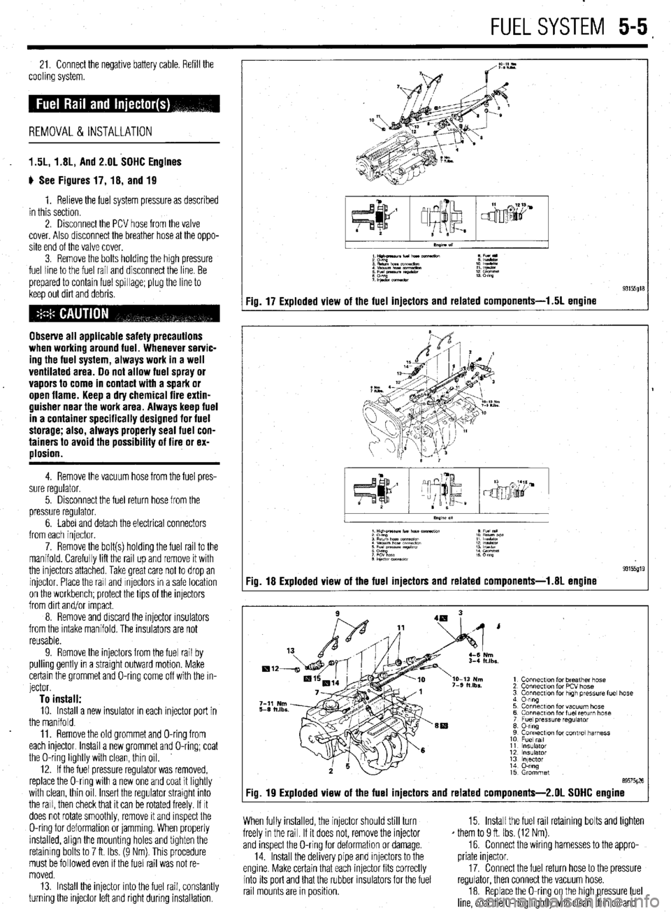
ti See Figures 17, 18, and 19
1. Relieve the fuel system pressure as described
in this section.
2. Disconnect the PCV hose from the valve
cover. Also disconnect the breather hose at the oppo-
site end of the valve cover.
3. Remove the bolts holding the high pressure
fuel line to the fuel rail and disconnect the line. Be
prepared to contain fuel spillage; plug the line to
keep out dirt and debris.
Observe all applicable safety precautions
when working around fuel. Whenever servic-
ing the fuel system, always work in a well
ventilated area. 00 not allow fuel spray or
vapors to come in contact with a spark or
open flame. Keep a dry chemical fire extin-
guisher near the work area. Always keep fuel
in a container specifically designed for fuel
storage; also, always properly seal fuel con-
tainers to avoid the possibility of fire or ex-
plosion.
4. Remove the vacuum hose from the fuel pres-
sure regulator.
5. Disconnect the fuel return hose from the
pressure regulator.
6. Label and detach the electrical connectors
from each injector.
7. Remove the bolt(s) holding the fuel rail to the
manifold. Carefully lift the rail up and remove it with
the injectors attached. Take great care not to drop an
injector Place the rail and Injectors in a safe location
on the workbench; protect the tips of the injectors
from dirt and/or Impact.
8. Remove and discard the injector rnsulators
from the intake manifold. The insulators are not
reusable.
9. Remove the injectors from the fuel rail by
pulling gently in a straight outward motion. Make
certain the grommet and O-ring come off with the in-
jector.
To install: 10. Install a new insulator in each injector port in
the manifold.
11. Remove the old grommet and O-ring from
each injector Install a new grommet and O-ring; coat
the O-ring lightly with clean, thin oil.
12. If the fuel pressure regulator was removed,
replace the O-ring with a new one and coat it lightly
with clean, thin oil Insert the regulator straight into
the rail, then check that it can be rotated freely. If It
does not rotate smoothly, remove it and inspect the
O-ring for deformation or jamming. When properly
installed, align the mounting holes and tighten the
retaining bolts to 7 ft. Ibs. (9 Nm). This procedure
must be followed even if the fuel rail was not re-
moved.
13. Install the injector into the fuel rail, constantly
turning the injector left and right during installation.
1Hilt4naunfu(norc e Fu(l
:E%!,,.,.- 1: IEE
: Efgz tz!z? :: %%I
;P&.xmeaw 13 m
Fig. 17 Exploded view of the fuel injectors and related components-l .5L engine
I
.xs.
1 Connection for breather hose
2 Connection for PCV hose
3 Connection for high tm?ss”re fuel hose
4 0-ring
5 Connection for vacuum hose
6 Connecr~on for fuel return hose
7 Fuel pressure regulator
8 0-ring
9 Connection for control harness
10 Fuel ml
11 Insulator
12 insulator
13 lnlector
14 O-ring
15 Grommet
89575026
Fig. 19 Exploded view of the fuel injectors and related components-2.01 SOHC engine
When fully installed, the injector should still turn
freely in the rail. If it does not, remove the injector
and inspect the O-ring for deformation or damage.
14. Install the delivery pipe and injectors to the
engine. Make certain that each injector fits correctly
into its port and that the rubber insulators for the fuel
rail mounts are in position. 15. Install the fuel rail retaining bolts and tighten
* them to 9 ft. Ibs. (12 Nm).
16. Connect the wiring harnesses to the appro-
priate injector.
17. Connect the fuel return hose to the pressure
regulator, then connect the vacuum hose.
18. Replace the O-ring on the high pressure fuel
line, coat the O-ring lightly with clean, thin oil and
Page 194 of 408
FUELSYSTEM 5-7
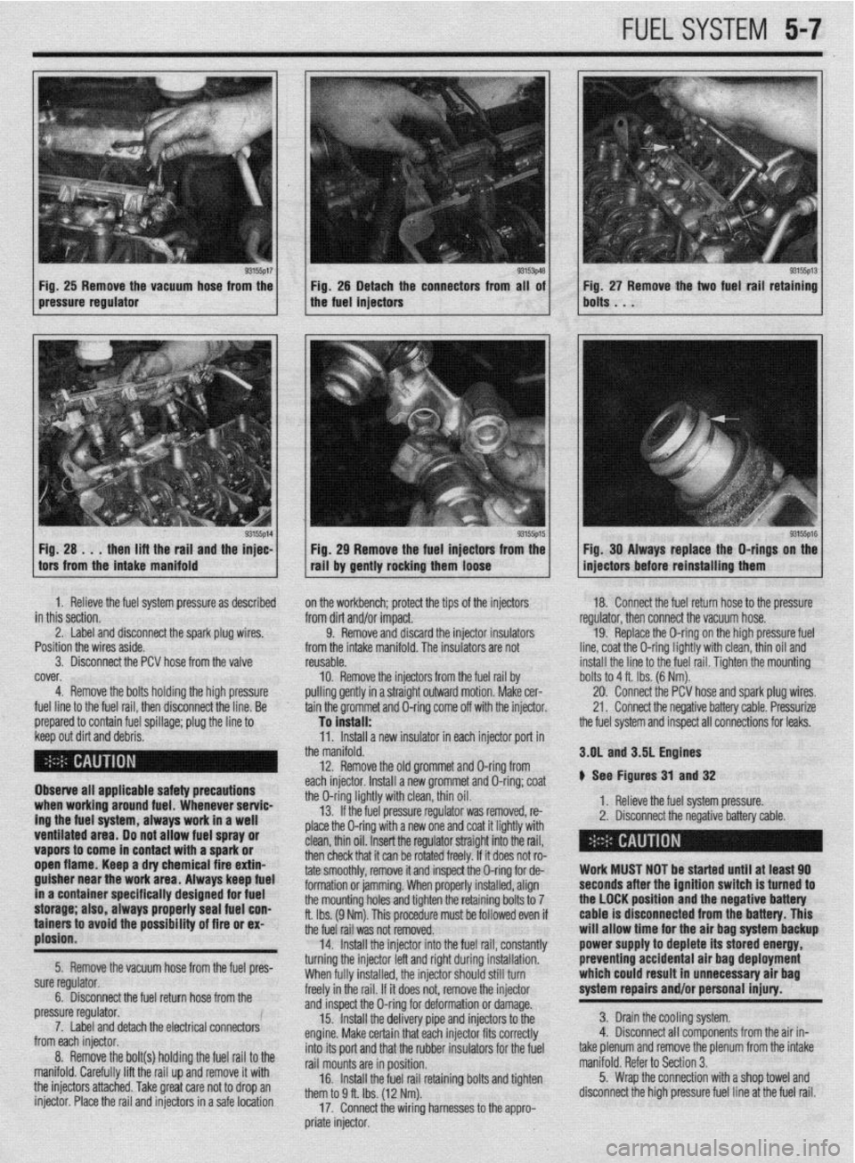
Fig, 25 Remove the vacuum hose from the Fig. 25 Detach the connectors from all of
pressure regulator the fuel injectors
1 H; :A ..;lt;;aft~rgi,i~;yl the ;F: 1 / . 93155p15 1 Fig 29 Remove the fuel injectors from the
tall by gently rocking them loose Fig. 27 Remove the two fuel rail retaining
bolts . . .
93155ps Fig. 30 Always replace the O-rings on the
injectors before reinstalling them
1. Relieve the fuel system pressure as described
in this section.
2. Label and disconnect the spark plug wires. ’
Position the wires aside.
3. Disconnect the PCV hose from the valve
cover,
4. Remove the bolts holding the high pressure
fuel line to the fuel rail, then disconnect the line. Be
prepared to contain fuel spillage; plug the line to on the workbench; protect the tips of the injectors
from dirt and/or impact.
9. Remove and discard the injector insulators
from the intake manifold. The insulators are not
reusable.
10. Remove the injectors from
pulling gently in a straight outwarc the fuel rail by
I motion. Make cer-
tain the grommet and O-ring come off with the injector. 18. Connect the fuel return hose to the pressure
regulator, then connect the vacuum hose.
19. Replace the O-ring on the high pressure fuel
line, coat the O-ring lightly with clean, thin oil and
install the line to the fuel rail. Tiahten the mountina
To install: -
the fuel system and inspect all connections for leaks. bolts to 4 ft. Ibs. (6 Nm).
20. Connect the PCV hose and spark plug wires.
21. Connect the negative battery cable. Pressurize
1. neneve me rueI system pressure.
2. Disconnect the negative battery cable. 3.OL and 3.5L Engines
# See Figures 31 and 32
> - ,. .* , ,
I
I
Work MUST NOT be started until at least 90
seconds after the ignition switch is turned to
the LOCK position and the negative battery
cable is disconnected from the battery. This
will allow time for the air bag system backup
power supply to deplete its stored energy,
preventing accidental air bag deployment
which could result in unnecessary air bag
system repairs and/or personal injury.
3. Drain the cooling system.
4. Disconnect all components from the air in-
take plenum and remove the plenum from the intake
manifold. Refer to Section 3.
5. Wrap the connection with a shop towel and
disconnect the high pressure fuel line at the fuel rail. keep out dirt and debris.
Observe all applicable safety precautions
when working around fuel. Whenever servic-
ing the fuel system, always work in a well
ventilated area. Do not allow fuel spray or
vapors to come in contact with a spark or
open flame. Keep a dry chemical fire extin-
guisher near the work area. Always keep fuel
in a container specifically designed for fuel
storage; also, always properly seal fuel con-
tainers to avoid the possfbility of fire or ex-
plosion.
5. Remove the vacuum hose from the fuel pres-
sure regulator.
6. Disconnect the fuel return hose from the
pressure regulator.
7. Label and detach the electrical connectors
from each injector.
8. Remove the bolt(s) holding the fuel rail to the
manifold. Carefully lift the rail up and remove it with
the injectors attached. Take great care not to drop an
injector. Place the rail and injectors in a safe location 11. Install a new insulator in each injector port in
the manifold.
12. Remove the old grommet and D-ring from
each injector. Install a new grommet and O-ring; coat
the O-ring lightly with clean, thin oil.
13. If the fuel pressure regulator was removed, re-
place the O-ring with a new one and coat it lightly with
clean, thin oil. Insert the regulator straight into the rail,
then check that it can be rotated freely. If it does not ro-
tate smoothly, remove it and inspect the O-ring for de-
formation or jamming. When properly installed, align
the mounting holes and tighten the retaining bolts to 7
ft. Ibs. (9 Nm). This procedure must be followed even if
the fuel rail was not removed.
14. Install the injector into the fuel rail, constantly
turning the injector left and right during installation.
When fully installed, the injector should still turn
freely in the rail. If it does not, remove the injector
and inspect the O-ring for deformation or damage.
15. Install the delivery pipe and injectors to the
engine. Make certain that each injector fits correctly
into its port and that the rubber insulators for the fuel
rail mounts are in position.
16. Install the fuel rail retaining bolts and tighten
them to 9 ff. Ibs. (12 Nm).
17. Connect the wiring harnesses to the appro-
priate injector.
Page 201 of 408
.
5-14 FUEL SYSTEM
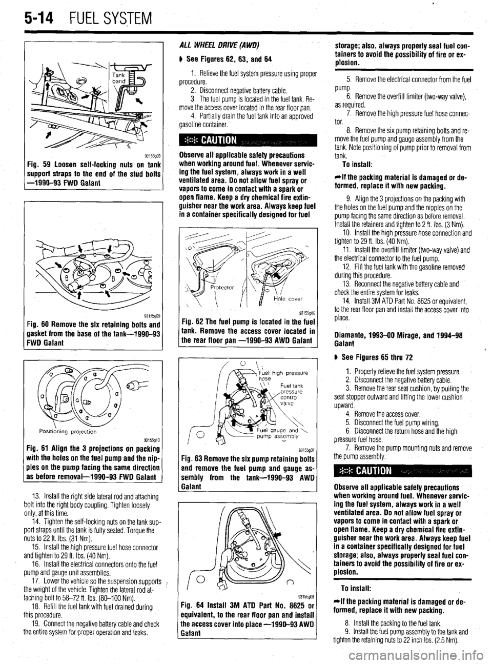
93155(10: ‘ig. 59 loosen self-locking nuts on tank
mpporf straps to the end of the stud bolts
-1990-93 FWD Galant
93i55Qo$ :ig. 60 Remove the six retaining bolts and
lasket from the base of the tank-1990-93
:WD Galant
Q m
0 a
cl@=
u a-
a al2
0
0
Q
a a
Posmdmng projectton 93155910 Fig. 61 Align the 3 projections on packing
with the holes on the fuel pump and the nip-
ples on the pump facing the same direction
as before removal-1990-93 FWD Galant
13. Install the right side lateral rod and attaching
bolt into the right body coupling. Tighten loosely
only, at this time.
14. Tighten the self-locking nuts on the tank sup-
port straps until the tank is fully seated. Torque the
nuts to 22 ft. Ibs. (31 Nm).
15. Install the high pressure fuel hose connector
and tighten to 29 ft. Ibs. (40 Nm).
16. Install the electrical connectors onto the fuel
pump and gauge unit assemblies.
17. Lower the vehicle so the suspension supports
the weight of the vehicle. Tighten the lateral rod at-
taching bolt to 58-72 ft Ibs. (So-100 Nm).
18. Refill the fuel tank with fuel drained during
this procedure.
19. Connect the negative battery cable and check
the entire system for proper operation and leaks. ALL WHEEL DRIVE (A WO)
# See Figures 62, 63, and 64
1. Relieve the fuel system pressure using proper
procedure.
2. Disconnect negative battery cable.
3. The fuel pump is located in the fuel tank. Re-
move the access cover located in the rear floor pan
4 Parbally drain the fuel tank into an approved
gasoline container.
Observe all applicable safety precautions
when workina around fuel. Whenever servic-
ing the fuel system, always work in a well
ventilated area. Do not allow fuel spray or
vapors to come in contact with a spark or
open flame. Keep a dry chemical fire extin-
guisher near the work area. Always keep fuel
in a container specifically designed for fuel
-ig. 62 The fuel pump is located in the fuel
r
ank. Remove the access cover located m
he rear floor pan -1990-93 AWD Galant
93155go7 Fig. 63 Remove the six pump retaining bolts
and remove the fuel pump and gauge as-
sembly from the tank-1990-93 AWD
1 Galant
93155goa Fig. 64 Install 3M ATD Part No. 8625 or
equivalent, to the rear floor pan and install
ihe access cover into place -1990-93 AWD
Ealant storage; also, always properly seal fuel con-
tainers to avoid the possibility of fire or ex-
plosion.
5 Remove the electrical connector from the fuel
pump.
6. Remove the overfill limiter (two-way valve),
as required.
7. Remove the high pressure fuel hose connec-
tor.
8. Remove the six pump retaming bolts and re-
move the fuel pump and gauge assembly from the
tank. Note positioning of pump prior to removal from
tank.
To install:
*If the packing material is damaged or de-
formed, replace it with new packing.
9. Align the 3 projections on the packing with
the holes on the fuel pump and the nipples on the
pump facmg the same direction as before removal.
Install the retainers and tlghten to 2 ft. Ibs. (3 Nm).
10. Install the high pressure hose connection and
tighten to 29 ft. Ibs. (40 Nm).
11. Install the overfill limiter (two-way valve) and
the electrical connector to the fuel pump.
12. Fill the fuel tank with the gasoline removed
during this procedure.
13. Reconnect the negative battery cable and
check the entire system for leaks.
14. Install 3M ATD Part No. 8625 or equivalent,
to the rear floor pan and install the access cover into
place.
Diamante, 1993-00 Mirage, and 1994-98
Galant
# See Figures 65 thru 72
1. Properly relieve the fuel system pressure.
2. Disconnect the negative battery cable.
3. Remove the rear seat cushion, by pulling the
seat stopper outward and lifting the lower cushion
upward.
4. Remove the access cover.
5. Disconnect the fuel pump wiring.
6. Disconnect the return hose and the high
pressure fuel hose.
7. Remove the pump mounting nuts and remove
the pump assembly.
Observe all applicable safety precautions
when working around fuel. Whenever servic-
ing the fuel system, always work in a well
ventilated area. Do not allow fuel spray or
vapors to come in contact with a spark or
open flame. Keep a dry chemical fire extin-
guisher near the work area. Always keep fuel
in a container specifically designed for fuel
storage; also, always properly seal fuel con-
tainers to avoid the possibility of fire or ex-
plosion.
To install:
rlf the packing material is damaged or de-
formed, replace it with new packing.
8. Install the packing to the fuel tank.
9. Install the fuel pump assembly to the tank and
tighten the retaining nuts to 22 inch Ibs. (2 5 Nm).
Page 202 of 408
FUELSYSTEM 5-15
*Tilt the float to the left of the vehicle, when
installing the pump assembly..
10. Connect the high pressure hose, return hose
and the fuel tank wiring.
11. Connect the negative battery cable.
12. Check the fuel pump for proper pressure and
inspect the entire system for leaks.
13. Apply sealant to the access cover and install
the cover.
14. Install the rear seat cushion.
1999-M Galant
b See Figures 65 thru 75 ’
1. Properly relieve the fuel system pressure.
2. Disconnect the negative battery cable.
3. Remove the rear seat cushion, by pulling the
seat stopper outward and lifting the lower cushion
upward.
4. Remove the access cover.
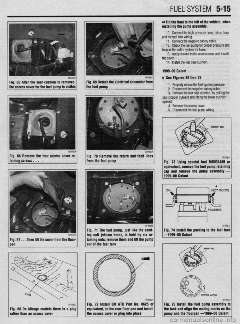
Fig. 73 Using special tool MB991480 or
1 equivaler It, remove the fuel pump retaining
I I
Fig. 71 The fuel pump, just like the send- Fig. 74 Install the packing to the fuel tank
-- 93155~03 ing unit (shown here), is held by six re- -1999-00 Galant
. _. ._. .
-. m and lift the pump
. . . then lift the cover from tne floor- tammg nuts; remove tne
out of the fuel tank
J I A/ -p,486
I
Fig. 75 lnsta
, II the fuel pump assembly toi
equivalent 72 Ins$ll 3M ATD Part No. 6625 ori /’
to the rear floor pan and install the tank and align the mating marks on the
the access cover or plug into place pump and the floorpan -1999110 Galant Fig, 68 On Mirage models there is a plug
rather than an access cover
Page 204 of 408
UNDERSTANDING AND
TROUBLESHOOTING
ELECTRICAL SYSTEMS 6-2
BASIC ELECTRICALTHEORY 6-2
HOW DOES ELECTRICITY WORK:
THEWATERANALOGY 6-2
OHM'S LAW 6-2
ELECTRICALCOMPONENTS 6-2
POWERSOURCE 6-2
GROUND 6-3
PROTECTIVE DEVICES 6-3
SWITCHES&RELAYS 6-3
LOAD 6-3
WIRING & HARNESSES 6-3
CONNECTORS 6-4
TEST EQUIPMENT 6-4
JUMPER WIRES 6-4
TEST LIGHTS 6-4
MULTIMETERS 6-5
TROUBLESHOOTING ELECTRICAL
SYSTEMS 6-5
TESTING 6-5
OPEN CIRCUITS 6-5
SHORT CIRCUITS 6-6
VOLTAGE 6-6
VOLTAGE DROP 6-6
RESISTANCE 6-8
WIRE AND CONNECTORREPAIR 6-6
BATTERY CABLES 6-7
DISCONNECTING THE CABLES 6-7
AIR BAG (SUPPLEMENTAL
RESTRAINT SYSTEM) 6-7
GENERALINFORMATION 6-7
SERVICE PRECAUTIONS 6-7
DISARMING 6-7
REARMING 6-7
HEATING AND AIR
CONDITIONING 6-7
BLOWER MOTOR 6-7
REMOVAL &INSTALLATION 6-7
HEATER CORE 6-9 INSTRUMENTS AND SWITCHES 6-17
INSTRUMENTCLUSTER 6-17
REMOVAL &INSTALLATION 6-17
GAUGES 6-18
REMOVAL&INSTALLATION 6-18
WINDSHIELD WIPER SWITCH 6-19
REMOVAL&INSTALLATION 6-19
REARWINDOWWIPERSWITCH 6-19
REMOVAL &INSTALLATION 6-19
DIMMER SWITCH 6-19
REMOVAL & INSTALLATION 6-19 .
HEADLIGHT SWITCH 6-19
REMOVAL & INSTALLATION 6-19
LIGHTING 6-19
HEADLIGHTS 6-19
REMOVAL &INSTALLATION 6-19
AIMINGTHEHEADLIGHTS 6-20
SIGNAL AND MARKER LIGHTS 6-21
REMOVAL &INSTALLATION 6-21
CIRCUIT PROTECTION 6-27
FUSES 6-27
REPLACEMENT 6-27
FUSIBLE LINKS 6-27
CIRCUIT BREAKERS 6-28
RESETTING AND/OR
REPLACEMENT 6-28
FLASHERS 6-28
REPLACEMENT 6-28
WIRING DIAGRAMS 6-31
REMOVAL & INSTALLATION 6-9
AIR CONDITIONING COMPONENTS 6-11
REMOVAL & INSTALLATION 6-11
CONTROLCABLES 6-12
ADJUSTMENT 6-12
CONTROL PANEL 6-12
REMOVAL & INSTALLATION 6-12
CRUISE CONTROL 6-13
ENTERTAINMENT SYSTEMS 6-14
RADIO RECEIVER/AMPLIFIER/TAPE
PLAYER/CD PLAYER 6-14
SPEAKERS 6-14
REMOVAL & INSTALLATION 6-14
WINDSHIELD WIPERS AND
WASHERS 6-15
WINDSHIELD WIPER BLADE AND
ARM 6-15
REMOVAL & INSTALLATION 6-15
WINDSHIELD WIPER MOTOR 6-16 _
REMOVAL &INSTALLATION 6-16
WINDSHIELD WASHER PUMP 6-17
REMOVAL &INSTALLATION 6-17