2024 FORD F650/750 warning
[x] Cancel search: warningPage 140 of 386
GENERAL INFORMATION
WARNING: Exceeding these ratingsby overloading can cause componentfailure resulting in property damage,personal injury or death.
Fluid Temperature
If the operating temperature exceeds250°F (121°C), the rate of axle lubricationoxidation increases and shortens the lifeof the lubricant and seals, requiring axlelubrication changes to become morefrequent to preserve the axle. Do notconsistently run extreme pressure (EP)lubricants above 250°F (121°C).
Axle Conversions
WARNING: When operating aloaded vehicle, the driver must keep alladjustable axles on the ground at alltimes, supporting their share of thevehicle’s load. Failure to do so canoverload other axles, tires, wheels,springs, steering components, brakesand frames, resulting in early componentfailure, loss of vehicle control, possibleproperty damage and personal injury.
We do not recommend, or approve,performing axle conversions. However, weunderstand that, on occasion, others installaftermarket add-on axles on the truckchassis that allow operator control forweight transfer from other axles (such asair lift axles).
2-SPEED REAR AXLE (IF EQUIPPED)
WARNING: Never shift atwo-speed axle when descending asteep grade as this may cause loss ofvehicle control and result in personalinjury.
Note:Do not shift between ranges whenthe speed control is on.
A two-speed rear axle allows the driver toselect a low range for greater pulling powerand a high range for greater road speedand fuel economy. You can also use theseranges to provide extra steps betweentransmission shifts when driving on steepgrades or fuel economy may be factors.
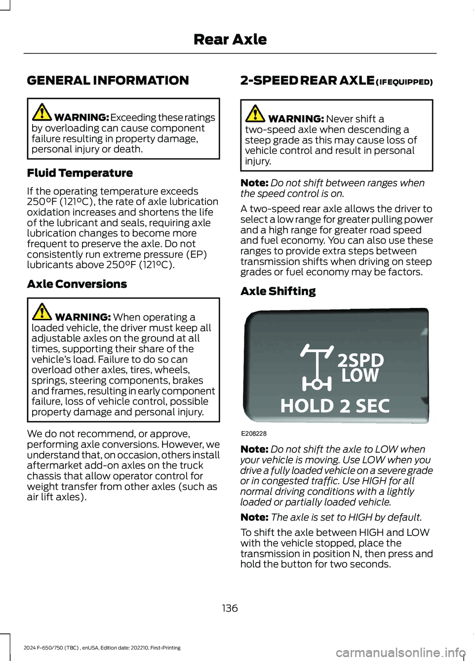
Axle Shifting
Note:Do not shift the axle to LOW whenyour vehicle is moving. Use LOW when youdrive a fully loaded vehicle on a severe gradeor in congested traffic. Use HIGH for allnormal driving conditions with a lightlyloaded or partially loaded vehicle.
Note:The axle is set to HIGH by default.
To shift the axle between HIGH and LOWwith the vehicle stopped, place thetransmission in position N, then press andhold the button for two seconds.
136
2024 F-650/750 (TBC) , enUSA, Edition date: 202210, First-PrintingRear AxleE208228
Page 141 of 386

WHAT IS THE PNEUMATIC
LOCKING DIFFERENTIAL
The pneumatic locking differential can lockor unlock the differential when the vehicleis moving or stopped. The differential lockprovides full power to both wheels whenextra traction is required.
HOW DOES THE PNEUMATIC
LOCKING DIFFERENTIAL
WORK
If your vehicle is equipped with apneumatic locking differential:
•Power is transmitted to the oppositewheel should one of the wheels beginto slip.
•Raise both wheels off the ground if itbecomes necessary to operate onewheel with the vehicle stationary.
The differential can be locked or unlockedwhen the vehicle is moving at a constantspeed of less than 25 mph (40 km/h) andwhile the wheels are not slipping. Do notlock the differential when the vehicle istraveling down steep grades and tractionis minimal.
Note:Do not use the differential lock atvehicle speeds above 25 mph (40 km/h).
When the differential is locked, thevehicle’s turning radius increases causingundersteer.
The differential lock and differential locklight automatically disengage at speedsabove 25 mph (40 km/h). The differentiallock remains off until the vehicle isrestarted or the differential lock switch isturned off then back on.
PNEUMATIC LOCKING
DIFFERENTIAL PRECAUTIONS
WARNING: Exceeding any vehicleweight rating can adversely affect theperformance and handling of yourvehicle, cause vehicle damage and canresult in the loss of control of yourvehicle, serious personal injury or death.
WARNING: Failure to raise all drivewheels with this type of differential couldcause the vehicle to move unexpectedly,resulting in property damage, personalinjury or death.
WARNING: Sudden accelerationon slippery surfaces could cause thewheels to spin, the vehicle to turnsideways on a crowned road surface orin a turn, possibly resulting in loss ofvehicle control and personal injury.
SWITCHING THE PNEUMATIC
LOCKING DIFFERENTIAL ON
AND OFF
Press and hold the button on the dash toturn the system on or off.
137
2024 F-650/750 (TBC) , enUSA, Edition date: 202210, First-PrintingPneumatic Locking DifferentialE366571
Page 143 of 386
GENERAL INFORMATION
Note: Occasional brake noise is normal. Ifa metal-to-metal, continuous grinding orcontinuous squeal sound is present, thebrake linings may be worn-out. Have thesystem checked as soon as possible. If thevehicle has continuous vibration or shudderin the steering wheel while braking, have thesystem checked as soon as possible.
All standard equipment brakes areself-adjusting. Automatic adjustment,when required, occurs whenever you applyand release the brakes during forward orreverse operation.
Know the required stopping distances forall driving conditions you may encounter.For longer brake lining life, take fulladvantage of engine braking power whencoming to a stop.
Wet brakes result in reduced brakingefficiency. Gently press the brake pedal afew times when driving from a car wash orstanding water to dry the brakes.
If the brakes do not grip well:
•Check brake adjustment.
•Check the brake linings for excessivewear.
•Check the system air pressure onvehicles with air brakes.
•Let the brakes cool if you have beenusing them excessively, as in mountaindriving or after several fast, high-speedstops.
•If you have been driving through deepwater, gently apply the brakes severaltimes while your vehicle is movingslowly.
Brake Over Accelerator
In the event the accelerator pedalbecomes stuck or entrapped, apply steadyand firm pressure to the brake pedal toslow the vehicle and reduce engine power.If you experience this condition, apply thebrakes and bring your vehicle to a safestop. Move the transmission to park (P),switch the engine off and apply the parkingbrake. Inspect the accelerator pedal forany interference. If none are found and thecondition persists, have your vehicle towedto the nearest authorized dealer
Anti-lock Brake System
This system helps you maintain steeringcontrol during emergency stops by keepingthe brakes from locking.
If the light does not illuminateduring start up, remains on orflashes, the system may bedisabled. It also momentarily illuminateswhen you switch the ignition on to confirmthe lamp is functional. If it does notilluminate when you switch the ignition on,or begins to flash at any time, have thesystem checked.
If you connect a PLC trailer withthe ignition on, the trailer ABSlight also illuminates. If the lightfails to illuminate, if it remains on after youstart the vehicle or continues to flash, havethe system serviced immediately.
See Warning Lamps and Indicators(page 67).
139
2024 F-650/750 (TBC) , enUSA, Edition date: 202210, First-PrintingBrakesE67020 E210335
Page 144 of 386
If the system is disabled, normalbraking is still effective. If thebrake warning lamp illuminateswith the parking brake released, have thesystem checked immediately. It alsomomentarily illuminates when you switchthe ignition on to confirm the lamp isfunctional. If it does not illuminate whenyou switch the ignition on, or begins toflash at any time, have the systemchecked.
HINTS ON DRIVING WITH
ANTI-LOCK BRAKES
The anti-lock brake system does noteliminate the risks when:
•You drive too closely to the vehicle infront of you.
•Your vehicle is hydroplaning.
•You take corners too fast.
•The road surface is poor.
Note: If the system activates, the brakepedal could pulse and may travel further.Maintain pressure on the brake pedal. Youmay also hear a noise from the system. Thisis normal.
PARKING BRAKE
Hydraulic Brakes (If Equipped)
WARNING: Always set the parkingbrake and leave your vehicle with thetransmission in park (P).
WARNING: This control is forparking only. Do not leave the vehicleunattended after setting the parkingbrake without placing the transmissionin park (P). We recommend using wheelchocks for hilly or off-roadcircumstances.
WARNING: Unexpected andpossibly sudden vehicle movement mayoccur if you do not take theseprecautions.
WARNING: If the parking brake isfully released, but the brake warninglamp remains illuminated, the brakesmay not be working properly. Have yourvehicle checked as soon as possible.
Apply the parking brake whenever thevehicle is parked. To set the parking brake,pull the handle up until it snaps into thelocked position.
When the parking brake is out ofadjustment, seek service immediately.
The parking brake warning lampin the instrument clusterilluminates, and remainsilluminated (when you switch on theignition), until you release the parkingbrake.
140
2024 F-650/750 (TBC) , enUSA, Edition date: 202210, First-PrintingBrakesE209041 E208810 E210347
Page 145 of 386
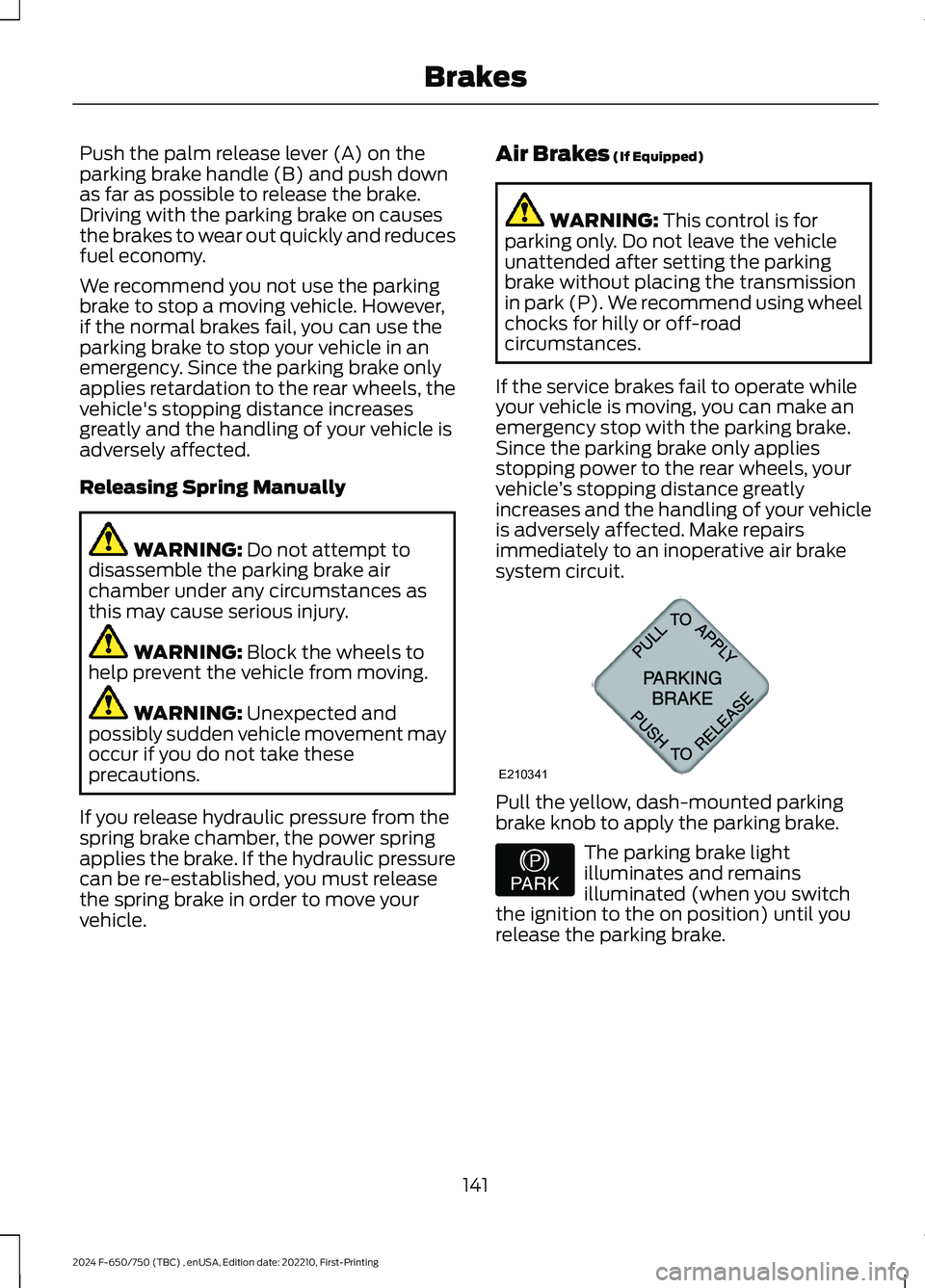
Push the palm release lever (A) on theparking brake handle (B) and push downas far as possible to release the brake.Driving with the parking brake on causesthe brakes to wear out quickly and reducesfuel economy.
We recommend you not use the parkingbrake to stop a moving vehicle. However,if the normal brakes fail, you can use theparking brake to stop your vehicle in anemergency. Since the parking brake onlyapplies retardation to the rear wheels, thevehicle's stopping distance increasesgreatly and the handling of your vehicle isadversely affected.
Releasing Spring Manually
WARNING: Do not attempt todisassemble the parking brake airchamber under any circumstances asthis may cause serious injury.
WARNING: Block the wheels tohelp prevent the vehicle from moving.
WARNING: Unexpected andpossibly sudden vehicle movement mayoccur if you do not take theseprecautions.
If you release hydraulic pressure from thespring brake chamber, the power springapplies the brake. If the hydraulic pressurecan be re-established, you must releasethe spring brake in order to move yourvehicle.
Air Brakes (If Equipped)
WARNING: This control is forparking only. Do not leave the vehicleunattended after setting the parkingbrake without placing the transmissionin park (P). We recommend using wheelchocks for hilly or off-roadcircumstances.
If the service brakes fail to operate whileyour vehicle is moving, you can make anemergency stop with the parking brake.Since the parking brake only appliesstopping power to the rear wheels, yourvehicle’s stopping distance greatlyincreases and the handling of your vehicleis adversely affected. Make repairsimmediately to an inoperative air brakesystem circuit.
Pull the yellow, dash-mounted parkingbrake knob to apply the parking brake.
The parking brake lightilluminates and remainsilluminated (when you switchthe ignition to the on position) until yourelease the parking brake.
141
2024 F-650/750 (TBC) , enUSA, Edition date: 202210, First-PrintingBrakesE210341 E208810
Page 146 of 386
Releasing the Parking Brake
WARNING: When your vehicle isstationary, keep the brake pedal fullypressed when shifting gears. Failure tofollow this instruction could result inpersonal injury, death or propertydamage.
Note:Read and understand the followingsteps and perform them whenever youprepare to drive the vehicle.
Note:The parking brake does not disengageunless sufficient system air pressure isavailable.
1.Press and hold the service brake pedalwhile the engine is running.
2.Select the appropriate drive gear.
3.Push and hold the yellowdash-mounted parking brake knob untilthe parking brake light turns off, thenrelease.
Parking Brake Light Illumination Dueto Low Air Pressure
If the air pressure becomes too low at anytime during vehicle operation, the parkingbrake may apply and the parking brakelight turns on.
If the parking brake applies due to low airpressure, immediate service is required tothe parking brake system.
Releasing Spring Brake with AirPressure
The air system in all vehicles withspring-actuated rear wheel parking brakeshas a valve on the governor for connectionto an outside air supply. The valve lets yourecharge the system with air from anoutside source, releasing thespring-actuated parking brakes. Yourvehicle is now ready to tow in anemergency.
You can only use an outside air source ifthe protected system is in operatingcondition. If you cannot restore air pressurein the protected air system, you mustrelease the spring-actuated brakesmanually.
Releasing Spring Manually
Do not use impact wrenches as they maydamage the piston and prevent propercaging of the spring. Do not apply morethan 50 lb.ft (68 Nm) to the release boltnut.
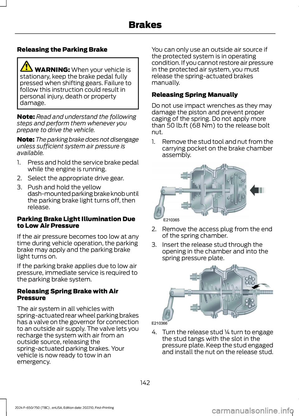
1.Remove the stud tool and nut from thecarrying pocket on the brake chamberassembly.
2.Remove the access plug from the endof the spring chamber.
3.Insert the release stud through theopening in the chamber and into thespring pressure plate.
4.Turn the release stud ¼ turn to engagethe stud tangs with the slot in thepressure plate. Keep the stud engagedand install the nut on the release stud.
142
2024 F-650/750 (TBC) , enUSA, Edition date: 202210, First-PrintingBrakesE210365 E210366
Page 147 of 386

5.Tighten the nut until the spring is fullycaged and brakes released. Do notloosen or remove the release stud andnut unless you completely assembleand securely clamp the brake chamber.
6.After restoring the air pressure,unscrew and remove the release studand install in the carrying pocket. Installthe access plug.
HILL START ASSIST -
VEHICLES WITH: HYDRAULIC
BRAKES
WARNING: The system does notreplace the parking brake. When youleave your vehicle, always apply theparking brake.
WARNING: You must remain inyour vehicle when the system turns on.At all times you are responsible forcontrolling your vehicle, supervising thesystem, and intervening if required.Failure to follow this instruction couldresult in the loss of control of yourvehicle, personal injury or death.
WARNING: The system will turnoff if a malfunction is apparent or if yourev the engine excessively. Failure to takecare may result in the loss of control ofyour vehicle, serious personal injury ordeath.
The system makes it easier to pull awaywhen your vehicle is on a slope withoutneeding to use the parking brake.
When the system is active, your vehicleremains stationary on the slope for two tothree seconds after you release the brakepedal. This allows time to move your footfrom the brake to the accelerator pedal.The brakes release when the engine has
developed sufficient torque to prevent yourvehicle from rolling down the slope. Thisis an advantage when pulling away on aslope, for example from a car park ramp,traffic lights or when reversing uphill intoa parking space.
When the vehicle is on a slope, the systemwill turn on automatically to preventvehicle rollback.
Note:There is no warning light to indicatethe system is either on or off.
Using Hill Start Assist
1.Press the brake pedal to bring yourvehicle to a complete standstill. Keepthe brake pedal pressed and shift intogear when facing uphill or reverse (R)when facing downhill.
2.If the sensors detect that your vehicleis on a slope, the system automaticallyactivates.
3.When you remove your foot from thebrake pedal, your vehicle remains onthe slope without rolling away forabout two to three seconds. This holdtime automatically extends if you arein the process of driving off.
4.Drive off in the normal manner. Thesystem releases the brakesautomatically.
Note:When you remove your foot from thebrake pedal and press the pedal again whenthe system is active, you will experiencesignificantly reduced brake pedal travel. Thisis normal.
Switching the System On and Off
Vehicles with Manual Transmission
You can switch this feature on or off in theinformation display. The systemremembers the last setting when you startyour vehicle.
143
2024 F-650/750 (TBC) , enUSA, Edition date: 202210, First-PrintingBrakes
Page 148 of 386
Vehicles with Automatic Transmission
When you switch the ignition on, thesystem automatically turns on. You cannotturn the system on or off.
AIR BRAKES
WARNING: Failure to maintainproper air brake adjustment can resultin reduction or loss of braking ability.
WARNING: Do not drive or continueto drive if the low air pressure buzzer issounding or the brake warning light is lit.These warnings indicate that air pressureis not to normal operating level.Continued use of the vehicle could resultin loss of braking ability.
WARNING: Avoid repeated lightapplication of the brake pedal. Thisdepletes air pressure faster and couldresult in loss of braking capability.
WARNING: Do not move thevehicle when the air pressure isinsufficient because the brake systemmay be inoperative.
After starting the engine, allow time for theair compressor to build air pressure to60 psi (414 kPa) before moving yourvehicle.
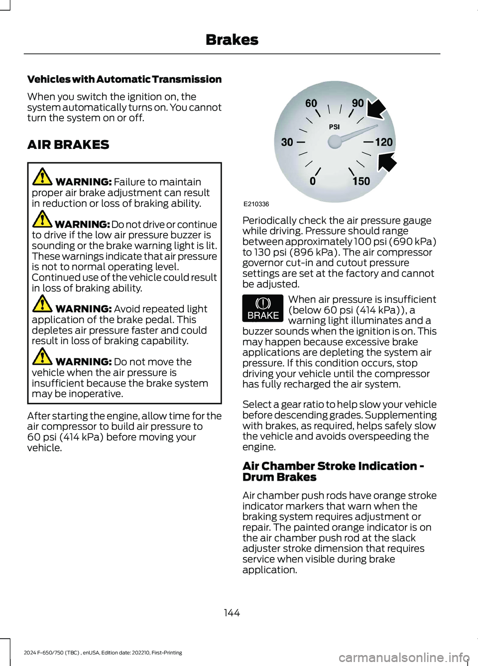
Periodically check the air pressure gaugewhile driving. Pressure should rangebetween approximately 100 psi (690 kPa)to 130 psi (896 kPa). The air compressorgovernor cut-in and cutout pressuresettings are set at the factory and cannotbe adjusted.
When air pressure is insufficient(below 60 psi (414 kPa)), awarning light illuminates and abuzzer sounds when the ignition is on. Thismay happen because excessive brakeapplications are depleting the system airpressure. If this condition occurs, stopdriving your vehicle until the compressorhas fully recharged the air system.
Select a gear ratio to help slow your vehiclebefore descending grades. Supplementingwith brakes, as required, helps safely slowthe vehicle and avoids overspeeding theengine.
Air Chamber Stroke Indication -Drum Brakes
Air chamber push rods have orange strokeindicator markers that warn when thebraking system requires adjustment orrepair. The painted orange indicator is onthe air chamber push rod at the slackadjuster stroke dimension that requiresservice when visible during brakeapplication.
144
2024 F-650/750 (TBC) , enUSA, Edition date: 202210, First-PrintingBrakesE210336 E206772