Page 218 of 386

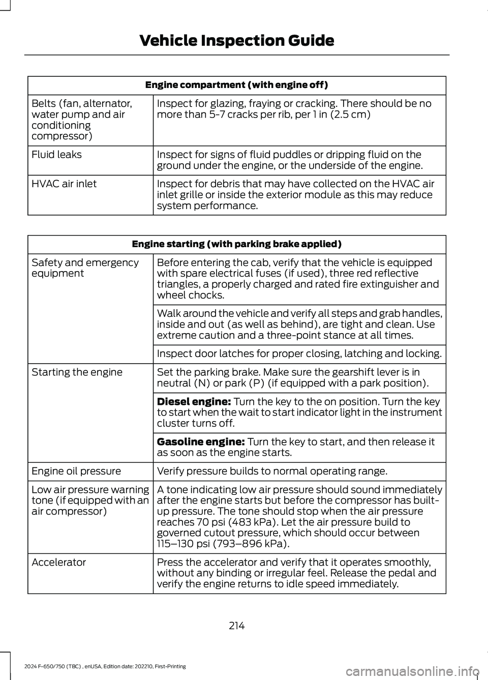
Engine compartment (with engine off)
Inspect for glazing, fraying or cracking. There should be nomore than 5-7 cracks per rib, per 1 in (2.5 cm)Belts (fan, alternator,water pump and airconditioningcompressor)
Inspect for signs of fluid puddles or dripping fluid on theground under the engine, or the underside of the engine.Fluid leaks
Inspect for debris that may have collected on the HVAC airinlet grille or inside the exterior module as this may reducesystem performance.
HVAC air inlet
Engine starting (with parking brake applied)
Before entering the cab, verify that the vehicle is equippedwith spare electrical fuses (if used), three red reflectivetriangles, a properly charged and rated fire extinguisher andwheel chocks.
Safety and emergencyequipment
Walk around the vehicle and verify all steps and grab handles,inside and out (as well as behind), are tight and clean. Useextreme caution and a three-point stance at all times.
Inspect door latches for proper closing, latching and locking.
Set the parking brake. Make sure the gearshift lever is inneutral (N) or park (P) (if equipped with a park position).Starting the engine
Diesel engine: Turn the key to the on position. Turn the keyto start when the wait to start indicator light in the instrumentcluster turns off.
Gasoline engine: Turn the key to start, and then release itas soon as the engine starts.
Verify pressure builds to normal operating range.Engine oil pressure
A tone indicating low air pressure should sound immediatelyafter the engine starts but before the compressor has built-up pressure. The tone should stop when the air pressurereaches 70 psi (483 kPa). Let the air pressure build togoverned cutout pressure, which should occur between115–130 psi (793–896 kPa).
Low air pressure warningtone (if equipped with anair compressor)
Press the accelerator and verify that it operates smoothly,without any binding or irregular feel. Release the pedal andverify the engine returns to idle speed immediately.
Accelerator
214
2024 F-650/750 (TBC) , enUSA, Edition date: 202210, First-PrintingVehicle Inspection Guide
Page 219 of 386

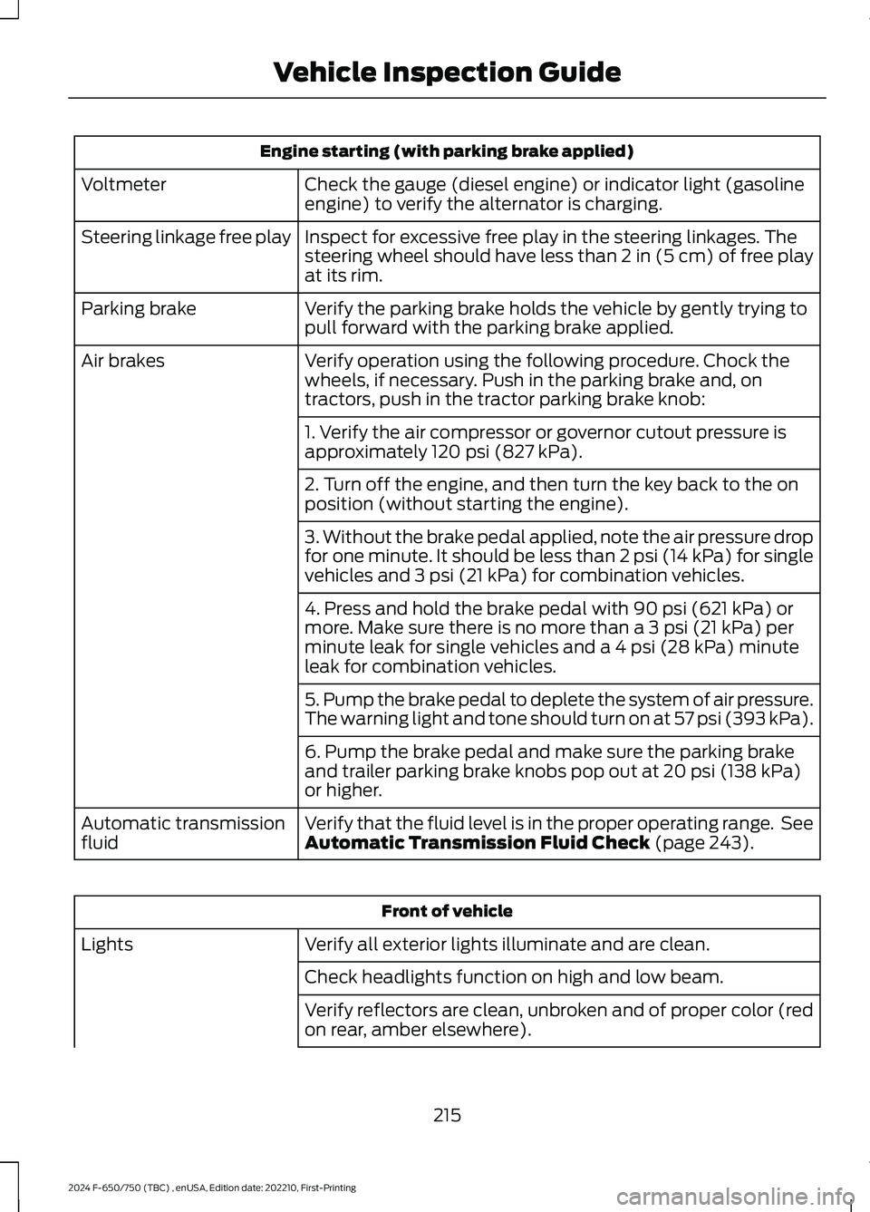
Engine starting (with parking brake applied)
Check the gauge (diesel engine) or indicator light (gasolineengine) to verify the alternator is charging.Voltmeter
Inspect for excessive free play in the steering linkages. Thesteering wheel should have less than 2 in (5 cm) of free playat its rim.
Steering linkage free play
Verify the parking brake holds the vehicle by gently trying topull forward with the parking brake applied.Parking brake
Verify operation using the following procedure. Chock thewheels, if necessary. Push in the parking brake and, ontractors, push in the tractor parking brake knob:
Air brakes
1. Verify the air compressor or governor cutout pressure isapproximately 120 psi (827 kPa).
2. Turn off the engine, and then turn the key back to the onposition (without starting the engine).
3. Without the brake pedal applied, note the air pressure dropfor one minute. It should be less than 2 psi (14 kPa) for singlevehicles and 3 psi (21 kPa) for combination vehicles.
4. Press and hold the brake pedal with 90 psi (621 kPa) ormore. Make sure there is no more than a 3 psi (21 kPa) perminute leak for single vehicles and a 4 psi (28 kPa) minuteleak for combination vehicles.
5. Pump the brake pedal to deplete the system of air pressure.The warning light and tone should turn on at 57 psi (393 kPa).
6. Pump the brake pedal and make sure the parking brakeand trailer parking brake knobs pop out at 20 psi (138 kPa)or higher.
Verify that the fluid level is in the proper operating range. SeeAutomatic Transmission Fluid Check (page 243).Automatic transmissionfluid
Front of vehicle
Verify all exterior lights illuminate and are clean.Lights
Check headlights function on high and low beam.
Verify reflectors are clean, unbroken and of proper color (redon rear, amber elsewhere).
215
2024 F-650/750 (TBC) , enUSA, Edition date: 202210, First-PrintingVehicle Inspection Guide
Page 258 of 386

Removal
1.Disconnect the fuel lines by squeezingthe connector tabs and pulling the linesstraight off.
2.Rotate the filter fully counterclockwiseuntil the peg is at the far end of the slot.
3.Pull the filter straight up from thebracket and discard the filter.
Installation
1.Install the new filter into the filterbracket. Turn the filter clockwise tolock it in place.
2.Reconnect the fuel lines.
3.Switch the ignition on for 30 secondsand then switch the ignition off.Repeat this operation six times in a rowto purge any trapped air from the fuelsystem.
ELECTRICAL SYSTEM
INSPECTION
Periodically inspect electrical connectorson the outside of the cab and on the engineand frame for corrosion and tightness.Exposed terminals, such as the fuel sender,cranking motor, alternator andfeed-through studs, should be cleaned andre-coated with a lubricant sealing greasesuch as Motorcraft Silicone Brake CaliperGrease and Dielectric Compound XG-3, orequivalent. This should include the groundcable connector for batteries, engine andcab as well as the jump-starting stud.
Accessory Feed Connections
Vehicle electrical systems are complex andoften include powertrain components,such as engine and transmission controls,instrument panels and ABS. While mostsystems operate on battery voltage (12volts), some systems can be as high as 90volts or as low as five volts. See theElectrical Circuit Diagram Manuals,available from your vehicle’s manufacturer,to make sure that any extra body lights andaccessory connections to circuits are bothappropriate and not overloaded. Do notmake modifications to any vehicle controlsystem without first contacting anauthorized dealer.
254
2024 F-650/750 (TBC) , enUSA, Edition date: 202210, First-PrintingMaintenanceE2262151 E22621423
Page 295 of 386
ENGINE SPECIFICATIONS - 6.7L DIESEL
6.7L V8 Diesel EngineEngine
406 in³ (6,651 cm³)Displacement.
Ultra Low Sulfur Diesel up to B20Required fuel.
1-3-7-2-6-5-4-8Firing order.
15.2:1Compression ratio.
Drivebelt Routing
Single Alternator
Single Alternator With Air BrakeCompressor
Drivebelt closest to the engine.A
Drivebelt furthest from theengine.B
291
2024 F-650/750 (TBC) , enUSA, Edition date: 202210, First-PrintingCapacities and SpecificationsE224819 E224825
Page 296 of 386
Dual AlternatorDual Alternator With Air BrakeCompressor
Drivebelt closest to the engine.A
Drivebelt furthest from theengine.B
Note:The belt routings show vehicles withair conditioning. When vehicles do not haveair conditioning, an idler pulley is in place ofthe A/C compressor.
ENGINE SPECIFICATIONS - 7.3L
7.3L V8 EngineEngine
445 in³ (7,293 cm³)Displacement.
Minimum 87 octaneRequired fuel.
1-5-4-8-6-3-7-2Firing order.
Coil near spark plug with spark plug wireIgnition system.
0.049 in (1.25 mm) - 0.053 in (1.35 mm)Spark plug gap.
10.5:1Compression ratio.
292
2024 F-650/750 (TBC) , enUSA, Edition date: 202210, First-PrintingCapacities and SpecificationsE224820 E224826
Page 297 of 386
Drivebelt Routing
Single Alternator
Drivebelt closest to the engine.A
Drivebelt furthest from theengine.B
Dual Alternator
Drivebelt closest to the engine.A
Drivebelt furthest from theengine.B
MOTORCRAFT PARTS - 6.7L DIESEL
Part NumberComponent
FL-2124-SEngine oil filter.1
FA-1909Foam pre-filter.
FA-2061Air filter.
FD-4637Fuel filter kit (2 included - engine and framerail mounted).
FT-221Transmission filter.
BH-31-XLTwo batteries (standard)(1500 CCA).
293
2024 F-650/750 (TBC) , enUSA, Edition date: 202210, First-PrintingCapacities and SpecificationsE388771 E388772