2021 ALFA ROMEO STELVIO stop start
[x] Cancel search: stop startPage 46 of 280
GETTING TO KNOW YOUR VEHICLE
44
Parking Lights
To turn on the parking lights and instrument
panel lights, rotate the headlight switch clock-
wise to the position. All of the parking lights
will turn on for eight minutes, and opening the
door activates an audible warning.
To leave only the lights on one side (right/left)
illuminated, move the multifunction lever
(located on the left side of the steering wheel)
to the side that you want to remain on. With
the parking lights on, the indicator light on
the instrument panel will illuminate.
To turn off the parking lights, rotate the head -
light switch back to the O (off) position.
Headlight Off Delay
To assist when exiting the vehicle, the “Head -
light Off Delay” feature will leave the head -
lights on for up to 90 seconds. This delay is
initiated when the ignition is placed in the OFF
position while the headlight switch is on, and
then the headlight switch is cycled off. Head -
light delay can be canceled by either turning
on the headlights or side lights, or by placing
the ignition in the ON position.
The function can be activated from the radio
system by selecting the following functions in
sequence on the main menu:
1. “Settings.”
2. “Lights.”
3. “Headlight Off Delay.”
Rear Fog Lights
The rear fog light switch is located within the
headlight switch.
Push the button, located in the center of
the headlight switch, to turn the rear fog lights
on/off.
The rear fog lights turn on only when the head -
lights or parking lights are also turned on. The
lights can be turned off by pushing the
button again or by turning the headlight switch
to the O (off) position.
When the engine is stopped with the rear fog
lights on, they will be off the next time the
engine is started.
Adaptive Headlight System (AFS) — If
Equipped
This is a system combined with Xenon head -
lights (Bi-Xenon 35 W headlamp, if equipped)
which directs the headlights horizontally, and
continuously and automatically adapts them
to the driving conditions around bends or
when cornering.
The system directs the headlights to light up
the road in the best way, taking into account
the speed of the vehicle and the bend or
corner angle, as well as the speed at which the
steering wheel is turned.
The adaptive lights are automatically activated
when the vehicle is started.
Turn Signals
Move the multifunction lever up or down to
activate the turn signals. The arrows on each
side of the instrument cluster flash to show
proper operation.
The or turn signal will blink on the instru -
ment panel.
Lane Change Assist
Lightly push the lever up or down once, without
moving beyond the detent, and the turn signal
will flash five times then automatically turn off.
To turn off the flashing before the end of the
cycle, move the lever in the opposite direction
until the first click (about half way).
INTERIOR LIGHTS
Courtesy lights are turned on when the front
doors are opened or when the dimmer control
is rotated to its farthest upward position. The
glove compartment light turns on automati -
cally when the glove compartment is opened
and turn off when it is closed. The door cour -
tesy lights illuminate when one of the front
doors is opened, and turn off when it is closed.
The liftgate courtesy lights turn on automati -
cally when the liftgate is opened and turn off
when it is closed. All of these lights turn on and
off regardless of the ignition status.
21_GU_OM_EN_USC_t.book Page 44
Page 47 of 280
45
Front Map Reading Lights
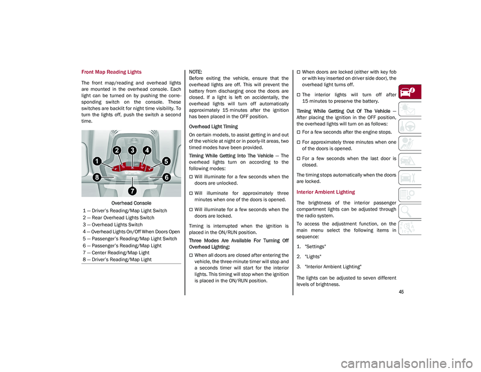
The front map/reading and overhead lights
are mounted in the overhead console. Each
light can be turned on by pushing the corre-
sponding switch on the console. These
switches are backlit for night time visibility. To
turn the lights off, push the switch a second
time.
Overhead Console
NOTE:
Before exiting the vehicle, ensure that the
overhead lights are off. This will prevent the
battery from discharging once the doors are
closed. If a light is left on accidentally, the
overhead lights will turn off automatically
approximately 15 minutes after the ignition
has been placed in the OFF position.
Overhead Light Timing
On certain models, to assist getting in and out
of the vehicle at night or in poorly-lit areas, two
timed modes have been provided.
Timing While Getting Into The Vehicle
— The
overhead lights turn on according to the
following modes:
Will illuminate for a few seconds when the
doors are unlocked.
Will illuminate for approximately three
minutes when one of the doors is opened.
Will illuminate for a few seconds when the
doors are locked.
Timing is interrupted when the ignition is
placed in the ON/RUN position.
Three Modes Are Available For Turning Off
Overhead Lighting:
When all doors are closed after entering the
vehicle, the three-minute timer will stop and
a seconds timer will start for the interior
lights. This timing will stop when the ignition
is placed in the ON/RUN position.
When doors are locked (either with key fob
or with key inserted on driver side door), the
overhead light turns off.
The interior lights will turn off after
15 minutes to preserve the battery.
Timing While Getting Out Of The Vehicle —
After placing the ignition in the OFF position,
the overhead lights will turn on as follows:
For a few seconds after the engine stops.
For approximately three minutes when one
of the doors is opened.
For a few seconds when the last door is
closed.
The timing stops automatically when the doors
are locked.
Interior Ambient Lighting
The brightness of the interior passenger
compartment lights can be adjusted through
the radio system.
To access the adjustment function, on the
main menu select the following items in
sequence:
1. "Settings"
2. "Lights"
3. "Interior Ambient Lighting"
The lights can be adjusted to seven different
levels of brightness.
1 — Driver’s Reading/Map Light Switch
2 — Rear Overhead Lights Switch
3 — Overhead Lights Switch
4 — Overhead Lights On/Off When Doors Open
5 — Passenger’s Reading/Map Light Switch
6 — Passenger’s Reading/Map Light
7 — Center Reading/Map Light
8 — Driver’s Reading/Map Light
21_GU_OM_EN_USC_t.book Page 45
Page 57 of 280
55
Humidity Sensor
The Humidity Sensor helps prevent the
windows from fogging up. The AUTO function
(indicator illuminated) must be on for the
Humidity Sensor to function.
When outside temperature is low, the system
may turn the compressor on and turn air recir-
culation off for safer driving.
Stop/Start
The Stop/Start system shuts off the engine
when the vehicle speed is 0 mph (0 km/h), as
a fuel conservation measure.
In order to maintain comfort in the cabin, the
Stop/Start feature will not activate if any of the
following conditions exist:
The Climate Control system is in AUTO mode
(indicator illuminated), and the vehicle has
yet to reach the set temperature
The Climate Control system is in LO
maximum cooling
The Climate Control system is in HI
maximum heating
The Climate Control system is in the
MAX-DEF status
When the Stop/Start system is active, the
engine will restart if the inside temperature
changes significantly, or if the LO setting, or
MAX-DEF setting, is activated. With Stop/Start system on (engine is OFF), air
flow is reduced to keep the compartment
comfort conditions for longer.
Until the temperature drastically changes
within the cabin, the climate control system
will continue to maintain the temperature
while the engine is off. By deactivating the
Stop/Start system with the button (located
by the headlight switch), the climate control
system operates normally according to the
settings.
NOTE:
In harsh climate conditions, limit the use of
the Stop/Start system to prevent the
compressor from continuously switching on
and off. This will cause rapid misting of the
windows and the accumulation of humidity
in the passenger compartment.
When the Stop/Start system is on, the
climate control system will always take air in
from outside, reducing the probability of the
windows fogging up.
System Maintenance
In winter months, the Climate Control system
must be turned on at least once a month for
approximately 10 minutes.
Have the system inspected at an authorized
dealer before the summer.
INTERIOR STORAGE AND
EQUIPMENT
Glove Compartment
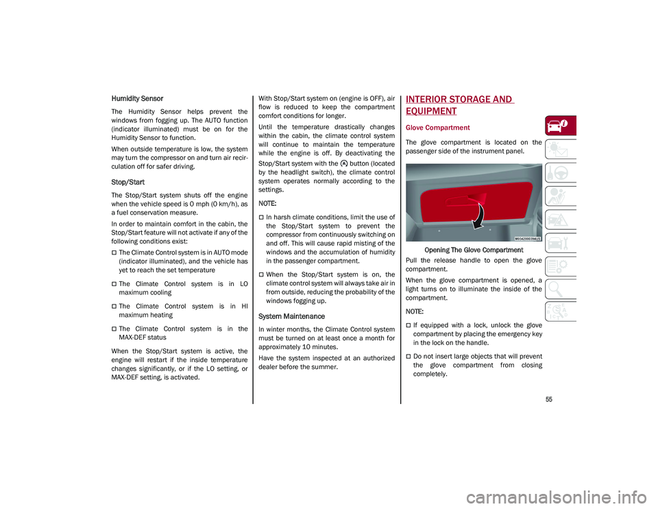
The glove compartment is located on the
passenger side of the instrument panel.
Opening The Glove Compartment
Pull the release handle to open the glove
compartment.
When the glove compartment is opened, a
light turns on to illuminate the inside of the
compartment.
NOTE:
If equipped with a lock, unlock the glove
compartment by placing the emergency key
in the lock on the handle.
Do not insert large objects that will prevent
the glove compartment from closing
completely.
21_GU_OM_EN_USC_t.book Page 55
Page 60 of 280
GETTING TO KNOW YOUR VEHICLE
58
Your mobile phone must be designed for Qi
wireless charging.
NOTE:
Do not place the key fob or any other type of
metal/magnetized object inside the mobile
phone housing or near the wireless
charging pad.
Be sure to place the mobile device correctly
(display facing upward) on the wireless
charging pad.
The ignition must be in the ON/RUN position
in order for the phone to charge.
To avoid interference with the key fob
search, the wireless charging pad will stop
charging when any door is opened.The following messages will display in the
radio system:
“Your phone is being charged” — The phone
has begun to charge.
“Phone Fully Charged” — The phone has
completed charging its battery.
“Foreign Object Detected” — The phone is
not enabled for wireless charging or an
object that is not permitted has been placed
on the wireless charging pad.
“Unavailable System” — There is a malfunc
-
tion with the wireless charging pad.
The driver can deactivate these messages
through the radio system. Refer to the Infor -
mation and Entertainment System Owner’s
Manual Supplement for further information.
POWER WINDOWS
Power Window Controls
The power window switches work with the igni -
tion in the ACC or ON/RUN position and for
three minutes after the ignition has been
placed in the OFF position. When one of the
front doors is opened, this operation is
disabled.
The window controls on the driver's door
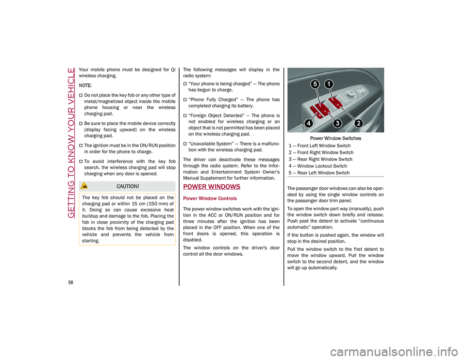
control all the door windows. Power Window Switches
The passenger door windows can also be oper -
ated by using the single window controls on
the passenger door trim panel.
To open the window part way (manually), push
the window switch down briefly and release.
Push past the detent to activate “continuous
automatic” operation.
If the button is pushed again, the window will
stop in the desired position.
Pull the window switch to the first detent to
move the window upward. Pull the window
switch to the second detent, and the window
will go up automatically.
CAUTION!
The key fob should not be placed on the
charging pad or within 15 cm (150 mm) of
it. Doing so can cause excessive heat
buildup and damage to the fob. Placing the
fob in close proximity of the charging pad
blocks the fob from being detected by the
vehicle and prevents the vehicle from
starting.
1 — Front Left Window Switch
2 — Front Right Window Switch
3 — Rear Right Window Switch
4 — Window Lockout Switch
5 — Rear Left Window Switch
21_GU_OM_EN_USC_t.book Page 58
Page 62 of 280
GETTING TO KNOW YOUR VEHICLE
60
The sunroof has three preset positions:
Fully closed
Comfort (intermediate opening)
Fully open
NOTE:
You cannot have the sunshade closed when
the sunroof is open.
Opening And Closing The Sunroof
To open the sunroof’s front panel, push the
open/close button toward the rear of the
vehicle to open to the comfort position (half
way). Pushing the button a second time will
open to the fully open position.
To close the sunroof, push the open/close
button toward the front of the vehicle. The roof
will close completely.
The automatic motion can be interrupted in
any position by pushing the open/close button
again.
Venting Sunroof
To bring the roof into vent position, push and
release the vent button.
This type of vent opening can be activated
regardless of the position of the sunroof.
When starting with the roof in the closed posi -
tion, pushing the vent button automatically
causes the sunroof to open to the vent posi -
tion. If the roof is already open, the button
must be held until the roof reaches the
vent-opening position.
Pushing the vent button again during auto -
matic movement of the roof will stop it.
Sunshade Operation
The sunshade is power operated.
Push the Power Shade open/close button
toward the rear of the vehicle to open the sun
shade.
Push the Power Shade open/close button
toward the front of the vehicle to close the sun
shade.
The automatic motion can be interrupted in
any position by pushing the Power Shade
open/close button again.
Pinch Protect Feature
The sunroof has an anti-pinch safety system
capable of detecting the presence of an
obstacle during the closing movement. If an
obstacle is detected, the system intervenes
and the movement of the sunroof is immedi -
ately reversed.
Re-Initialization Procedure
Automatic operation of the sunroof must be
re-initialized in case of faulty sunroof opera -
tion. It may also be necessary to initialize the
sunroof after the vehicle’s battery has been
disconnected and then reconnected.
NOTE:
The anti-pinch safety device is deactivated
during the re-initialization procedure.
WARNING!
Never leave children unattended in a
vehicle, or with access to an unlocked
vehicle. Never leave the key fob in or near
the vehicle, or in a location accessible to chil -
dren. Do not leave the ignition of a vehicle
equipped with keyless ignition in the ON/
RUN mode. Occupants, particularly unat -
tended children, can become entrapped by
the power sunroof while operating the power
sunroof switch. Such entrapment may result
in serious injury or death.
In a collision, there is a greater risk of
being thrown from a vehicle with an open
sunroof. You could also be seriously
injured or killed. Always fasten your seat
belt properly and make sure all passen -
gers are also properly secured.
Do not allow small children to operate the
sunroof. Never allow your fingers, other
body parts, or any object, to project
through the sunroof opening. Injury may
result.
CAUTION!
Do not open the sun roof if a roof rack or
crossbars are fitted. Do not open the sun
roof if there is snow or ice on it: you may
damage it.
21_GU_OM_EN_USC_t.book Page 60
Page 76 of 280
GETTING TO KNOW YOUR INSTRUMENT PANEL
74
(Continued)
To access and the change the setting, turn and
push the Rotary Pad or press the desired
setting on the touchscreen.
WARNING LIGHTS AND
MESSAGES ON THE
INSTRUMENT PANEL
The following pages consist of warning lights
and messages.
NOTE:
The warning light turns on together with a
dedicated message and/or chime when
applicable. These indications are precau-
tionary and as such must not be considered
as exhaustive and/or alternative to the
information contained in the Owner’s
Manual, which you are advised to read care -
fully in all cases. Always refer to the informa -
tion in this section in the event of a failure
indication.
The failure indicators appearing on the
display are divided into two categories: very
serious and less serious faults. Serious
faults are indicated by a repeated and
prolonged warning cycle. Less serious faults
are indicated by a warning cycle with a
shorter duration. You can stop the warning
cycle in both cases by pushing the button
located on the windshield wiper stalk. The
instrument panel warning light will stay on
until the cause of the failure is eliminated.
Red Warning Lights
Air Bag Warning Light
This warning light will illuminate to
indicate a fault with the air bag, and
will turn on for four to eight seconds
as a bulb check when the ignition is
placed in the ON/RUN or ACC/ON/RUN posi -
tion. This light will illuminate with a single
chime when a fault with the air bag has been
detected, it will stay on until the fault is
cleared. If the light is either not on during
startup, stays on, or turns on while driving,
have the system inspected at an authorized
dealer as soon as possible.
Brake Warning Light
This warning light monitors various
brake functions, including brake
fluid level and parking brake applica -
tion. If the brake light turns on it may
indicate that the parking brake is applied, that
the brake fluid level is low, or that there is a
problem with the Anti-Lock Brake System
reservoir.
If the light remains on when the parking brake
has been disengaged, and the fluid level is at
the full mark on the master cylinder reservoir,
it indicates a possible brake hydraulic system
malfunction or that a problem with the Brake
Booster has been detected by the Anti-Lock
Brake System (ABS) / Electronic Stability
Control (ESC) system. In this case, the light will
remain on until the condition has been corrected. If the problem is related to the
brake booster, the ABS pump will run when
applying the brake, and a brake pedal pulsa
-
tion may be felt during each stop.
The dual brake system provides a reserve
braking capacity in the event of a failure to a
portion of the hydraulic system. A leak in either
half of the dual brake system is indicated by
the Brake Warning Light, which will turn on
when the brake fluid level in the master
cylinder has dropped below a specified level.
The light will remain on until the cause is
corrected.
NOTE:
The light may flash momentarily during sharp
cornering maneuvers, which change fluid level
conditions. The vehicle should have service
performed, and the brake fluid level checked.
If brake failure is indicated, immediate repair
is necessary.
WARNING!
The fault of the warning light is signaled by
the turning on of the icon on the instru -
ment panel. In this case, the warning light
may not indicate any faults with the
restraint systems. Before proceeding,
contact an authorized dealer to have the
system checked immediately.
21_GU_OM_EN_USC_t.book Page 74
Page 78 of 280
GETTING TO KNOW YOUR INSTRUMENT PANEL
76
required. However, the conventional brake
system will continue to operate normally if the
brake indicator light is not on.
If the ABS light is on, the brake system should
be serviced as soon as possible to restore the
benefits of Anti-Lock Brakes. If the ABS light
does not turn on when the ignition is placed in
the ON/RUN position, have the light inspected
by an authorized dealer.
Electronic Stability Control (ESC) Indicator
Light — If Equipped
When the ignition is cycled to ON, the
indicator light illuminates, but
should turn off as soon as the engine
is started.
ESC System Intervention : Intervention by the
system is indicated by the flashing of the indi -
cator light: it indicates that the vehicle is in crit -
ical stability and grip conditions.
ESC System Failure : If the indicator light does
not turn off, or if it stays on with the engine
running, a failure was found in the ESC
system.
Hill Start Assist System Failure : The illumina-
tion of the indicator light indicates a Hill Start
Assist system failure.
In these cases, contact an authorized dealer
as soon as possible.
Electronic Stability Control (ESC) OFF
Indicator Light — If Equipped
When the ignition is cycled to ON, the
indicator light illuminates, but
should turn off as soon as the engine
is started.
The indicator light illuminates to indicate that
some active safety systems have been
partially or totally deactivated
Ú
page 145.
When the active safety systems are reacti -
vated, the indicator light turns off.
Tire Pressure Low Warning Light
The indicator light will illuminate to
indicate that the tire pressure is
lower than the recommended value
and/or that slow pressure loss is
occurring. In these cases, optimal tire duration
and fuel consumption may not be guaranteed.
In any situation in which the message on the
display is “See Manual”
Ú
page 161.
Tire Pressure Monitoring System (TPMS)
Warning Light
The warning light switches on and a
message is displayed to indicate
that the tire pressure is lower than
the recommended value and/or that
slow pressure loss is occurring. In these cases,
optimal tire duration and fuel consumption
may not be guaranteed. Should one or more tires be in the condition
mentioned above, the display will show the
indications corresponding to each tire.
Each tire, including the spare (if provided),
should be checked monthly when cold and
inflated to the inflation pressure recom
-
mended by the vehicle manufacturer on the
vehicle placard or tire inflation pressure label.
If your vehicle has tires of a different size than
the size indicated on the vehicle placard or tire
inflation pressure label, you should determine
the proper tire inflation pressure for those
tires.
As an added safety feature, your vehicle has
been equipped with a TPMS that illuminates a
low tire pressure telltale when one or more of
your tires is significantly underinflated. Accord -
ingly, when the low tire pressure telltale illumi -
nates, you should stop and check your tires as
soon as possible, and inflate them to the
proper pressure. Driving on a significantly
underinflated tire causes the tire to overheat
and can lead to tire failure. Under inflation
CAUTION!
Do not continue driving with one or more
flat tires as handling may be compromised.
Stop the vehicle, avoiding sharp braking
and steering. If a tire puncture occurs,
repair immediately using the dedicated tire
repair kit and contact an authorized dealer
as soon as possible.
21_GU_OM_EN_USC_t.book Page 76
Page 79 of 280
77
also reduces fuel efficiency and tire tread life,
and may affect the vehicle’s handling and
stopping ability.
Please note that the TPMS is not a substitute
for proper tire maintenance, and it is the
driver’s responsibility to maintain correct tire
pressure, even if under inflation has not
reached the level to trigger illumination of the
TPMS low tire pressure telltale.
Your vehicle has also been equipped with a
TPMS malfunction indicator to indicate when
the system is not operating properly. The
TPMS malfunction indicator is combined with
the low tire pressure telltale. When the system
detects a malfunction, the telltale will flash for
approximately one minute and then remain
continuously illuminated. This sequence will
continue upon subsequent vehicle start-ups
as long as the malfunction exists. When the
malfunction indicator is illuminated, the
system may not be able to detect or signal low
tire pressure as intended. TPMS malfunctions
may occur for a variety of reasons, including
the installation of replacement or alternate
tires or wheels on the vehicle that prevent the
TPMS from functioning properly. Always check
the TPMS malfunction telltale after replacing
one or more tires or wheels on your vehicle to
ensure that the replacement or alternate tires
and wheels allow the TPMS to continue to
function properly.
Rear Fog Lights
The indicator illuminates when the
rear fog light is activated.
Engine Check/Malfunction Indicator Light
(MIL)
In normal conditions, when the igni-
tion is cycled to ON, the indicator
light illuminates, but it should turn
off as soon as the engine is started.
The operation of the indicator light may be
checked by the traffic police using specific
devices. Comply with the laws and regulations
of the country where you are driving. Under these conditions, the vehicle can
continue traveling at moderate speed but
without demanding excessive effort from the
engine or high speed. Prolonged use of the
vehicle with the indicator light on constantly
may cause damage. Contact an authorized
dealer as soon as possible.
Forward Collision Warning (FCW) System
This indicator light informs the driver
that the frontal collision alarm func
-
tion is not enabled.
Drive carefully and contact an authorized
dealer as soon as possible.
Fuel Reserve/Limited Range
The indicator light (or the symbol in
the display) illuminates when about
2.4 gallons (9 liters) of fuel is left in
the tank.
WARNING!
The TPMS has been optimized for the
original equipment tires and wheels. TPMS
pressures and warning have been
established for the tire size equipped on
your vehicle. Undesirable system operation
or sensor damage may result when using
replacement equipment that is not of the
same size, type, and/or style. Aftermarket
wheels can cause sensor damage. Using
aftermarket tire sealants may cause the
Tire Pressure Monitoring System (TPMS)
sensor to become inoperable. After using
an aftermarket tire sealant it is
recommended that you take your vehicle to
an authorized dealership to have your
sensor function checked.
CAUTION!
If, turning the ignition device to ON, the
warning light does not turn on or if it
turns on steadily or flashing when traveling
(on some versions together with the
message on the display), contact an
authorized dealer as soon as possible.
21_GU_OM_EN_USC_t.book Page 77