2021 ALFA ROMEO STELVIO stop start
[x] Cancel search: stop startPage 142 of 280
STARTING AND OPERATING
140
Towing Requirements — Trailer Brakes
Do not interconnect the hydraulic brake
system or vacuum system of your vehicle
with that of the trailer. This could cause
inadequate braking and possible personal
injury.
An electronically actuated trailer brake
controller is required when towing a trailer
with electronically actuated brakes. When
towing a trailer equipped with a hydraulic
surge actuated brake system, an electronic
brake controller is not required.
Trailer brakes are recommended for trailers
over 1,000 lbs (453 kg) and required for
trailers in excess of 2,000 lbs (907 kg).
Towing Requirements — Trailer Lights And
Wiring
Whenever you pull a trailer, regardless of the
trailer size, stoplights and turn signals on the
trailer are required for motoring safety.
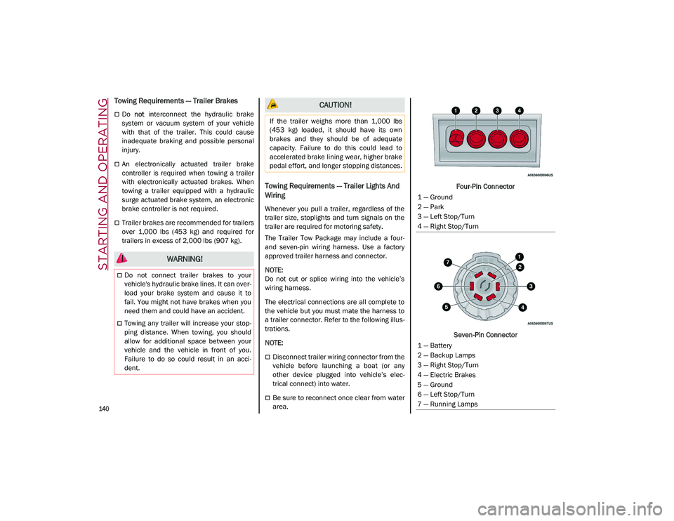
The Trailer Tow Package may include a four-
and seven-pin wiring harness. Use a factory
approved trailer harness and connector.
NOTE:
Do not cut or splice wiring into the vehicle’s
wiring harness.
The electrical connections are all complete to
the vehicle but you must mate the harness to
a trailer connector. Refer to the following illus -
trations.
NOTE:
Disconnect trailer wiring connector from the
vehicle before launching a boat (or any
other device plugged into vehicle’s elec -
trical connect) into water.
Be sure to reconnect once clear from water
area. Four-Pin Connector
Seven-Pin Connector
WARNING!
Do not connect trailer brakes to your
vehicle's hydraulic brake lines. It can over -
load your brake system and cause it to
fail. You might not have brakes when you
need them and could have an accident.
Towing any trailer will increase your stop -
ping distance. When towing, you should
allow for additional space between your
vehicle and the vehicle in front of you.
Failure to do so could result in an acci -
dent.
CAUTION!
If the trailer weighs more than 1,000 lbs
(453 kg) loaded, it should have its own
brakes and they should be of adequate
capacity. Failure to do this could lead to
accelerated brake lining wear, higher brake
pedal effort, and longer stopping distances.
1 — Ground
2 — Park
3 — Left Stop/Turn
4 — Right Stop/Turn
1 — Battery
2 — Backup Lamps
3 — Right Stop/Turn
4 — Electric Brakes
5 — Ground
6 — Left Stop/Turn
7 — Running Lamps
21_GU_OM_EN_USC_t.book Page 140
Page 144 of 280
STARTING AND OPERATING
142
Removing The Receiver
When the receiver is no longer needed, discon-
nect the electrical connections and remove it
from its position using the directions below:
1. Remove the safety split ring from the locking pin.
2. Pull the locking pin out of the trailer hitch.
3. Remove the receiver from the trailer hitch.
SUGGESTIONS FOR DRIVING
Saving Fuel
Below are some suggestions which may help
you save fuel and lower the amount of harmful
emissions released into the atmosphere.
Vehicle Maintenance
Checks and operations should be carried out
in accordance with the Maintenance Plan
Ú
page 208.
Tires
Check the tire pressures at least once every
four weeks: if the pressure is too low,
consumption levels increase as resistance to
rolling is higher.
NOTE:
Tire pressure that is too high can cause
premature tire wear, reduced control, etc. Unnecessary Loads
Do not travel with an overloaded liftgate. The
weight of the vehicle and its arrangement
greatly affect fuel consumption and stability.
Electric Devices
Use electrical systems only for the amount of
time needed. The rear window defroster, addi
-
tional headlights, windshield wipers and
heater blower fan require a considerable
amount of energy; increasing the current
uptake increases fuel consumption (by up to
+25% when city driving).
Climate Control System
Using the climate control system will increase
consumption: use standard ventilation when
the temperature outside permits.
Devices For Aerodynamic Control
The use of non-certified devices for aerody -
namic control may adversely affect air drag
and consumption levels.
Driving Style
Starting
Do not warm up the engine at low or high revs
when the vehicle is stationary; this causes the
engine to warm up more slowly, thereby
increasing fuel consumption and emissions. It
is therefore advisable to drive off immediately,
slowly, avoiding high speeds: by doing this the
engine will warm up more quickly. Unnecessary Actions
Avoid revving up when starting at traffic lights
or before stopping the engine. This action is
unnecessary and causes increased fuel
consumption and pollution.
Gear Selection
Use a high gear when traffic and road condi
-
tions allow it. Using a low gear for faster accel -
eration will increase fuel consumption.
Improper use of a high gear increases
consumption, emissions and engine wear.
Max. Speed
Fuel consumption considerably increases as
speed increases. Maintain a constant speed,
avoiding unnecessary braking and accelera -
tion, which cost in terms of both fuel consump -
tion and emissions.
Acceleration
Accelerating violently severely affects
consumption and emissions: acceleration
should be gradual and should not exceed the
maximum torque.Conditions Of Use
Cold Starting
Short trips and frequent cold starts will not
allow the engine to reach optimum operating
temperature. This results in a significant
increase in consumption levels (from +15 to
+30% in city driving) and emissions.
21_GU_OM_EN_USC_t.book Page 142
Page 147 of 280
145
(Continued)
SAFETY
This very important section describes the
safety systems that your vehicle may be
equipped with, and provides instructions on
how to use them correctly.
ACTIVE SAFETY SYSTEMS
The vehicle may be equipped with the
following active safety devices:
Anti-Lock Brake System (ABS)
Active Torque Vectoring (ATV) System
Dynamic Steering Torque (DST) System
Drive Train Control (DTC) System
Electronic Stability Control (ESC) System
Hill Descent Control (HDC) System
Hill Start Assist (HSA) System
Panic Brake Assist (PBA) System
Traction Control System (TCS)
For system operation, see the following pages.
Anti-Lock Brake System (ABS)
An integral part of the braking system, the ABS
prevents one or more wheels from locking and
slipping in all road surface conditions, regard -
less of the intensity of the braking action. The
system ensures that the vehicle can be
controlled even during emergency braking,
allowing the driver to optimize stopping
distances. The system intervenes during braking when
the wheels are about to lock, typically in emer
-
gency braking or low-grip conditions where
locking may be more frequent.
The system also improves control and stability
of the vehicle when braking on a surface
where the grip of the left and right wheels
varies, such as in a corner.
The Electronic Braking Force Distribution
(EBD) system works with the ABS, allowing the
brake force to be distributed between the front
and rear wheels.
System Intervention
The ABS equipped on this vehicle is provided
with the "Brake-By-Wire", Integrated Brake
System (IBS), function. With this system, the
command given by pressing the brake pedal is
not transmitted hydraulically, but electrically.
Therefore, the light pulsation that is felt on the
pedal with the traditional system is no longer
noticeable.Active Torque Vectoring (ATV) System — If
Equipped
The dynamic drive control is used to optimize
and balance the drive torque between the
wheels of the same axles. The ATV system
improves the grip in turns, sending more drive
torque to the external wheel.
WARNING!
The ABS contains sophisticated electronic
equipment that may be susceptible to
interference caused by improperly
installed or high output radio transmitting
equipment. This interference can cause
possible loss of anti-lock braking capa -
bility. Installation of such equipment
should be performed by qualified profes -
sionals.
Pumping of the Anti-Lock Brakes will
diminish their effectiveness and may lead
to a collision. Pumping makes the stop -
ping distance longer. Just press firmly on
your brake pedal when you need to slow
down or stop.
The ABS cannot prevent the natural laws
of physics from acting on the vehicle, nor
can it increase braking or steering effi -
ciency beyond that afforded by the condi -
tion of the vehicle brakes and tires or the
traction afforded.
The ABS cannot prevent collisions,
including those resulting from excessive
speed in turns, following another vehicle
too closely, or hydroplaning.
The capabilities of an ABS equipped
vehicle must never be exploited in a reck -
less or dangerous manner that could jeop -
ardize the user’s safety or the safety of
others.
WARNING! (Continued)
21_GU_OM_EN_USC_t.book Page 145
Page 150 of 280
SAFETY
148
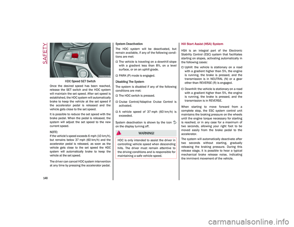
HDC Speed SET Switch
Once the desired speed has been reached,
release the SET switch and the HDC system
will maintain the set speed. After set speed is
established, the HDC system will automatically
brake to keep the vehicle at the set speed if
the accelerator pedal is released and the
vehicle gets close to the set speed.
It is possible to reduce the set speed with the
brake pedal. When the pedal is released, the
system will adjust the set speed to the new
current speed.
NOTE:
If the vehicle’s speed exceeds 6 mph (10 km/h),
but remains below 37 mph (60 km/h) and the
accelerator pedal is released, as soon as the
vehicle gets close to the set speed the HDC
system will automatically brake to keep the
vehicle at the set speed.
The driver can cancel HDC system intervention
at any time by pressing the accelerator pedal. System Deactivation
The HDC system will be deactivated, but
remain available, if any of the following condi
-
tions are met:
The vehicle is traveling on a downhill slope
with a gradient less than 8%, on a level
surface, or on an uphill grade.
PARK (P) mode is engaged.
Disabling The System
The system is disabled if any of the following
conditions are met:
The HDC switch is pressed.
Cruise Control/Adaptive Cruise Control is
activated.
A vehicle speed of 37 mph (60 km/h) is
exceeded.
System deactivation is shown by the icon
on the display turning off.
Hill Start Assist (HSA) System
HSA is an integral part of the Electronic
Stability Control (ESC) system that facilitates
starting on slopes, activating automatically in
the following cases:
Uphill: the vehicle is stationary on a road
with a gradient higher than 5%, the engine
is running, the brake is pressed, and the
transmission is in NEUTRAL (N) or a gear
other than REVERSE (R) is engaged.
Downhill: the vehicle is stationary on a road
with a gradient higher than 5%, the engine
is running, the brake is pressed, and the
transmission is in REVERSE.
When starting to move forward from a
complete stop, the ESC system control unit
maintains the braking pressure on the wheels
until the engine torque necessary for starting
is reached, or in any case for a maximum of
two seconds, allowing your right foot to be
moved easily from the brake pedal to the
accelerator.
The system will automatically deactivate after
two seconds without starting, gradually
releasing the braking pressure. During this
release stage, it is possible to hear a typical
mechanical brake release noise, indicating
the imminent movement of the vehicle.
WARNING!
HDC is only intended to assist the driver in
controlling vehicle speed when descending
hills. The driver must remain attentive to
the driving conditions and is responsible for
maintaining a safe vehicle speed.
21_GU_OM_EN_USC_t.book Page 148
Page 154 of 280
SAFETY
152
Operating Mode
The system may be activated/deactivated via
the radio system. To access the function,
select the following items on the main menu in
sequence:
1. “Driving Assistance”
2. “Blind Spot Alert”
“Blind Spot Alert”, “Visual” Mode
When the system is enabled, the warning light
within the door mirror on the side of the
detected object illuminates.
The visual warning on the mirror will blink if the
driver activates the turn signals, indicating a
lane change.
The warning light will be constant if the driver
stays in the same lane.
“Blind Spot Alert” Function Deactivation
When the system is deactivated (“Blind Spot
Alert” mode off), the BSM or RCP systems will
not emit an audible or a visual warning.
The BSM system will store the operating mode
that was active when the engine was stopped.
Each time the engine is started, the operating
mode stored previously will be recalled and
used
Ú
page 268.
Active Blind Spot Assist (ABSA) System — If
Equipped
The ABSA system is to help avoid/limit lateral
collisions with cars coming from adjacent lanes changing the vehicle’s trajectory in order
to try to keep it in the detected lane.
The system warns the driver about the pres
-
ence of other vehicles in the detection area by
illuminating the warning light located within
the door mirror on the side in which the other
vehicle was detected and by means of an
acoustic signal and/or vibration on the
steering wheel and/or counter-steering torque
on the steering wheel (if the respective item on
the “Driver Assistance” menu is set up and
then “Safety” is selected on the radio system).
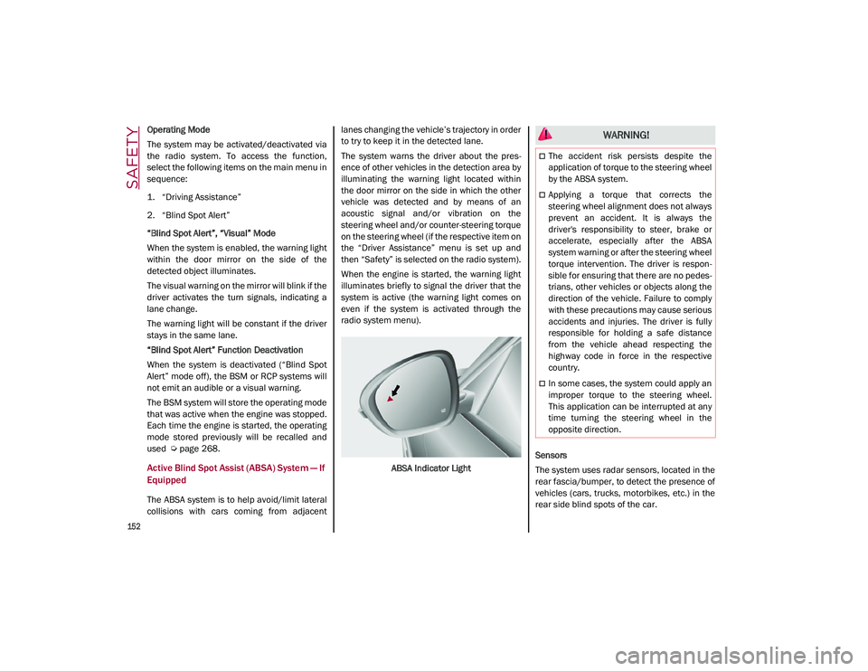
When the engine is started, the warning light
illuminates briefly to signal the driver that the
system is active (the warning light comes on
even if the system is activated through the
radio system menu).
ABSA Indicator Light Sensors
The system uses radar sensors, located in the
rear fascia/bumper, to detect the presence of
vehicles (cars, trucks, motorbikes, etc.) in the
rear side blind spots of the car.
WARNING!
The accident risk persists despite the
application of torque to the steering wheel
by the ABSA system.
Applying a torque that corrects the
steering wheel alignment does not always
prevent an accident. It is always the
driver's responsibility to steer, brake or
accelerate, especially after the ABSA
system warning or after the steering wheel
torque intervention. The driver is respon
-
sible for ensuring that there are no pedes -
trians, other vehicles or objects along the
direction of the vehicle. Failure to comply
with these precautions may cause serious
accidents and injuries. The driver is fully
responsible for holding a safe distance
from the vehicle ahead respecting the
highway code in force in the respective
country.
In some cases, the system could apply an
improper torque to the steering wheel.
This application can be interrupted at any
time turning the steering wheel in the
opposite direction.
21_GU_OM_EN_USC_t.book Page 152
Page 202 of 280
IN CASE OF EMERGENCY
200
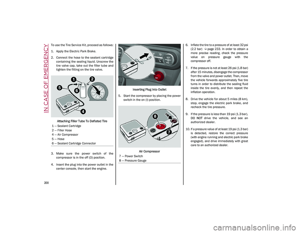
To use the Tire Service Kit, proceed as follows:
1. Apply the Electric Park Brake.
2. Connect the hose to the sealant cartridgecontaining the sealing liquid. Unscrew the
tire valve cap, take out the filler tube and
tighten the fitting on the tire valve.
Attaching Filler Tube To Deflated Tire
3. Make sure the power switch of the compressor is in the off (O) position.
4. Insert the plug into the power outlet in the center console, then start the engine. Inserting Plug Into Outlet
5. Start the compressor by placing the power switch in the on (I) position.
Air Compressor
6. Inflate the tire to a pressure of at least 32 psi
(2.2 bar)
Ú page 233. In order to obtain a
more precise reading, check the pressure
value on pressure gauge with the
compressor off.
7. If the pressure is not at least 26 psi (1.8 bar) after 15 minutes, disengage the compressor
from the valve and power outlet. Then, move
the vehicle forwards approximately five tire
turns in order to distribute the sealing fluid
inside the tire evenly, and then repeat the
inflation operation.
8. Drive the vehicle for about 5 miles (8 km), stop, engage the electric park brake, and
recheck the tire pressure.
9. If the pressure is less than 19 psi (1.3 bar), DO NOT drive the vehicle, and see an
authorized dealer.
10. If a pressure value of at least 19 psi (1.3 bar) is detected, restore the correct pressure
(with engine running and electric park brake
engaged), and drive immediately with great
care to an authorized dealer.
1 — Sealant Cartridge
2 — Filler Hose
4 — Air Compressor
5 — Hose
6 — Sealant Cartridge Connector
7 — Power Switch
8 — Pressure Gauge
21_GU_OM_EN_USC_t.book Page 200
Page 206 of 280
IN CASE OF EMERGENCY
204
4. Disconnect the positive (+) end of thejumper cable from the positive (+) post of
the vehicle with the discharged battery.
If frequent jump starting is required to start
your vehicle, you should have the battery and
charging system inspected at an authorized
dealer.
Bump Starting
Never jump start the engine by pushing,
towing or coasting downhill.
NOTE:
You cannot start a vehicle with an automatic
transmission by pushing it.
ENGINE OVERHEATING
If your vehicle is overheating, it will need to be
serviced at an authorized dealer.
Engine overheating may occur in situations
such as (but not limited to) extreme environ -
mental temperatures or frequent engine
stops/starts. If the engine becomes over -heated, the Engine Temperature Warning
Light in the instrument cluster will illuminate
along with a dedicated message
Ú
page 79.
In any of the following situations, you can
reduce the potential for overheating by taking
the appropriate action.
On the highways — slow down.
In city traffic — while stopped, place the
transmission in NEUTRAL, but do not
increase engine idle speed.
NOTE:
There are steps that you can take to slow down
an impending overheat condition:
If your Air Conditioner (A/C) is on, turn it off.
The A/C system adds heat to the engine
cooling system and turning the A/C off can
help remove this heat.
You can also turn the temperature control
to maximum heat, the mode control to floor
and the blower control to high. This allows
the heater core to act as a supplement to
the radiator and aids in removing heat from
the engine cooling system.
NOTE:
If the cooling fan does not operate while the
engine is running, the engine temperature
will increase. Stop the engine and contact
an authorized dealer.
If the engine continues to overheat or
frequently overheats, have the cooling
system inspected. The engine could be seri
-
ously damaged unless repairs are made.
Contact an authorized dealer.
CAUTION!
Accessories plugged into the vehicle power
outlets draw power from the vehicle’s
battery, even when not in use (i.e., cellular
phones, etc.). Eventually, if plugged in long
enough without engine operation, the
vehicle’s battery will discharge sufficiently
to degrade battery life and/or prevent the
engine from starting.
WARNING!
You or others can be badly burned by hot
engine coolant (antifreeze) or steam from
your radiator. If you see or hear steam
coming from under the hood, do not open
the hood until the radiator has had time to
cool. Never try to open a cooling system
pressure cap when the radiator or coolant
bottle is hot.
CAUTION!
Driving with a hot cooling system could
damage your vehicle. If temperature gauge
reads “H”, pull over and stop the vehicle.
Idle the vehicle with the air conditioner
turned off until the pointer drops back into
the normal range. If the pointer remains on
the “H”, turn the engine off immediately,
and call for service.
21_GU_OM_EN_USC_t.book Page 204
Page 221 of 280
219
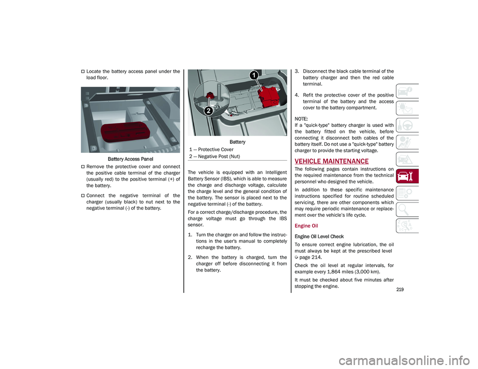
Locate the battery access panel under the
load floor.Battery Access Panel
Remove the protective cover and connect
the positive cable terminal of the charger
(usually red) to the positive terminal (+) of
the battery.
Connect the negative terminal of the
charger (usually black) to nut next to the
negative terminal (-) of the battery. Battery
The vehicle is equipped with an Intelligent
Battery Sensor (IBS), which is able to measure
the charge and discharge voltage, calculate
the charge level and the general condition of
the battery. The sensor is placed next to the
negative terminal (-) of the battery.
For a correct charge/discharge procedure, the
charge voltage must go through the IBS
sensor.
1. Turn the charger on and follow the instruc -
tions in the user's manual to completely
recharge the battery.
2. When the battery is charged, turn the charger off before disconnecting it from
the battery. 3. Disconnect the black cable terminal of the
battery charger and then the red cable
terminal.
4. Refit the protective cover of the positive terminal of the battery and the access
cover to the battery compartment.
NOTE:
If a "quick-type" battery charger is used with
the battery fitted on the vehicle, before
connecting it disconnect both cables of the
battery itself. Do not use a "quick-type" battery
charger to provide the starting voltage.
VEHICLE MAINTENANCE
The following pages contain instructions on
the required maintenance from the technical
personnel who designed the vehicle.
In addition to these specific maintenance
instructions specified for routine scheduled
servicing, there are other components which
may require periodic maintenance or replace -
ment over the vehicle’s life cycle.
Engine Oil
Engine Oil Level Check
To ensure correct engine lubrication, the oil
must always be kept at the prescribed level
Ú
page 214.
Check the oil level at regular intervals, for
example every 1,864 miles (3,000 km).
It must be checked about five minutes after
stopping the engine.
1 — Protective Cover
2 — Negative Post (Nut)
21_GU_OM_EN_USC_t.book Page 219