2021 ALFA ROMEO STELVIO dashboard
[x] Cancel search: dashboardPage 44 of 280

GETTING TO KNOW YOUR VEHICLE
42
NOTE:
If the indicator light stays on constantly,
programming is complete and the garage
door/device should activate when the
HomeLink® button is pressed.
To program the two remaining HomeLink®
buttons, repeat each step for each
remaining button. DO NOT erase the chan-
nels.
If you unplugged the garage door opener/
device for programming, plug it back in at this
time.
Reprogramming A Single HomeLink® Button
(Canadian/Gate Operator)
To reprogram a channel that has been previ -
ously trained, follow these steps:
1. Place the ignition to the ON/RUN position.
2. Press and hold the desired HomeLink® button until the indicator light begins to
flash after 20 seconds. Do not release the
button.
3. Without releasing the button, proceed with “Canadian/Gate Operator Programming”
step 2 and follow all remaining steps.
EXTERIOR LIGHTS
Headlight Switch
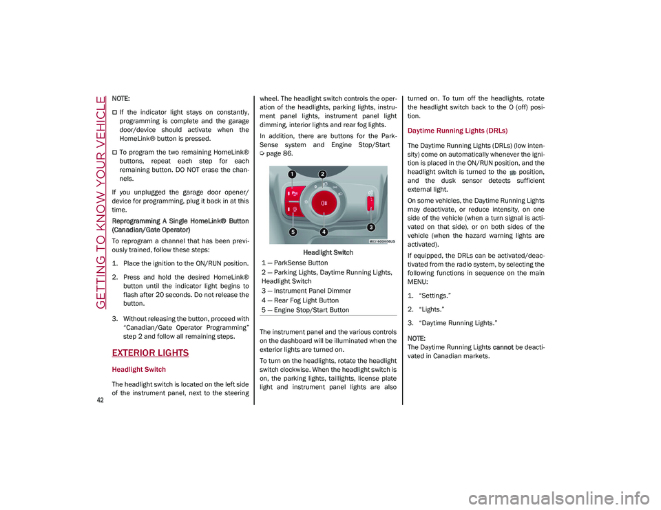
The headlight switch is located on the left side
of the instrument panel, next to the steering wheel. The headlight switch controls the oper
-
ation of the headlights, parking lights, instru -
ment panel lights, instrument panel light
dimming, interior lights and rear fog lights.
In addition, there are buttons for the Park -
Sense system and Engine Stop/Start
Ú
page 86.
Headlight Switch
The instrument panel and the various controls
on the dashboard will be illuminated when the
exterior lights are turned on.
To turn on the headlights, rotate the headlight
switch clockwise. When the headlight switch is
on, the parking lights, taillights, license plate
light and instrument panel lights are also turned on. To turn off the headlights, rotate
the headlight switch back to the O (off) posi
-
tion.
Daytime Running Lights (DRLs)
The Daytime Running Lights (DRLs) (low inten -
sity) come on automatically whenever the igni -
tion is placed in the ON/RUN position, and the
headlight switch is turned to the position,
and the dusk sensor detects sufficient
external light.
On some vehicles, the Daytime Running Lights
may deactivate, or reduce intensity, on one
side of the vehicle (when a turn signal is acti -
vated on that side), or on both sides of the
vehicle (when the hazard warning lights are
activated).
If equipped, the DRLs can be activated/deac -
tivated from the radio system, by selecting the
following functions in sequence on the main
MENU:
1. “Settings.”
2. “Lights.”
3. “Daytime Running Lights.”
NOTE:
The Daytime Running Lights cannot be deacti -
vated in Canadian markets.
1 — ParkSense Button
2 — Parking Lights, Daytime Running Lights,
Headlight Switch
3 — Instrument Panel Dimmer
4 — Rear Fog Light Button
5 — Engine Stop/Start Button
21_GU_OM_EN_USC_t.book Page 42
Page 56 of 280

GETTING TO KNOW YOUR VEHICLE
54
the flow of air. The air vanes of the center
outlets and outboard outlets can be moved up
and down or side to side to regulate airflow
direction. There is a shut off wheel located
below the air vanes to shut off or adjust the
amount of airflow from these outlets.
Bi-Level Mode
Air comes from the instrument panel
outlets and floor outlets. A slight
amount of air is directed through the
defrost and side window demister
outlets.
NOTE:
Bi-Level mode is designed under comfort
conditions to provide cooler air out of the
panel outlets and warmer air from the floor
outlets.
Floor Mode
Air comes from the floor outlets. A
slight amount of air is directed
through the defrost and side window
demister outlets. This setting heats
the passenger compartment the quickest.
Mix Mode
Air is directed through the floor,
defrost, and side window demister
outlets. This setting works best in
cold or snowy conditions that require
extra heat to the windshield. This setting is
good for maintaining comfort while reducing
moisture on the windshield.
Front Defrost And Panel Mode
Air flow is distributed between the
windshield demisting/defrosting
vents and side/central dashboard
vents. This setting allows air to flow
to the windshield on sunny days.
Front Defrost And Bi-Level Mode
Air flow is distributed to all vents.
Switching The Climate Control System On/
Off
To Turn Off The Climate Control System
Rotate the Air Speed Adjustment Knob
completely counterclockwise to turn off the
Climate Control system.
With the air conditioner is off:
Air recirculation is on
The A/C compressor is off
The fan is off
The heated rear window can be activated/
deactivated
NOTE:
The Climate Control system stores the previ -
ously set temperatures and resumes opera -
tion when any button on the system is pushed. To Turn On The Climate Control System
To switch the Climate Control system on in
automatic mode, push the AUTO button.
Operating Mode
The Climate Control system can be activated
in different ways. It is recommended to use the
automatic function. Push the AUTO button and
set the desired temperatures.
The automatic system adjusts the tempera
-
ture, quantity, and distribution of air intro -
duced into the passenger compartment. It
also controls air recirculation and the activa -
tion of the air conditioner.
At any time during automatic operation, you
can change the temperature, activate or deac -
tivate the Rear Defrost, activate SYNC, acti -
vate or deactivate the air conditioner, and
activate or deactivate air recirculation. The
system will automatically adjust to the new
settings.
Climate Control Display Settings
The Climate Control settings are visible on the
radio screen.
The display on the radio system is a pop up
window, which is activated by pushing the
buttons or turning the knobs on the Climate
Control system. The indicator lights located on
the buttons and knobs indicate that the
selected feature is on/off. If no operation is
performed for a predetermined time, the
pop-up will close on the display.
21_GU_OM_EN_USC_t.book Page 54
Page 200 of 280

IN CASE OF EMERGENCY
198
23. Remove the jack.
24. Use the wheel wrench to fully tighten thebolts, passing alternately from one bolt to
the diagonally opposite one.
To obtain a more accurate reading, it is advis -
able to check the pressure of the compact
spare tire on the pressure gauge with the
compressor off.
NOTE:
Do not stow the deflated tire in the compact
spare tire location.
The compressor was designed for inflating the
compact spare tire. Do not use it for inflating
mattresses, rafts, etc.
NOTE:
Spare tires are intended for temporary use
only.
Have the full-sized tire repaired or replaced, as
soon as possible.
TIRE SERVICE KIT — IF
EQUIPPED
Description
If a tire is punctured, you can make an emer -
gency repair using the Tire Service Kit located
in the rear storage area under the load plat -
form.
1. Stop the vehicle in a position where you can repair the tire safely. You should be as
far as possible from the side of the road,
and in a position that is not dangerous for
oncoming traffic. Turn on the Hazard
Warning Flashers, remove the safety
triangle from the luggage compartment,
and place it at a suitable distance from the
vehicle to make other drivers aware of
your presence.
2. Verify that the valve stem (on the wheel with the deflated tire) is in a position that
is near to the ground. This will allow the tire repair kit hoses to reach the valve stem
and keep the tire service kit flat on the
ground.
3. Place the gear selector in PARK (P).
4. Apply the electric park brake and turn the engine OFF.
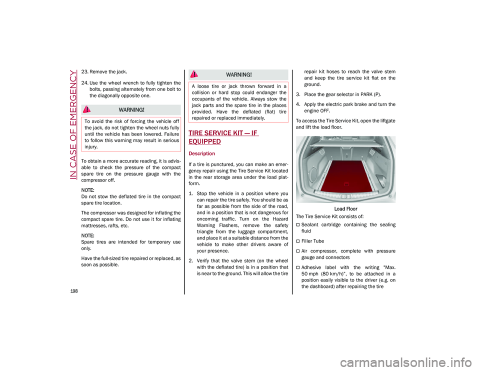
To access the Tire Service Kit, open the liftgate
and lift the load floor.
Load Floor
The Tire Service Kit consists of:
Sealant cartridge containing the sealing
fluid
Filler Tube
Air compressor, complete with pressure
gauge and connectors
Adhesive label with the writing "Max.
50 mph (80 km/h)”, to be attached in a
position easily visible to the driver (e.g. on
the dashboard) after repairing the tire
WARNING!
To avoid the risk of forcing the vehicle off
the jack, do not tighten the wheel nuts fully
until the vehicle has been lowered. Failure
to follow this warning may result in serious
injury.
WARNING!
A loose tire or jack thrown forward in a
collision or hard stop could endanger the
occupants of the vehicle. Always stow the
jack parts and the spare tire in the places
provided. Have the deflated (flat) tire
repaired or replaced immediately.
21_GU_OM_EN_USC_t.book Page 198
Page 255 of 280

253
For the enthusiasts, the technician, or those
who just want to know every detail of their
vehicle, useful information on understanding
how your vehicle works is contained in this
chapter and illustrated with data, tables, and
graphics.
VEHICLE IDENTIFICATION
NUMBER (VIN)
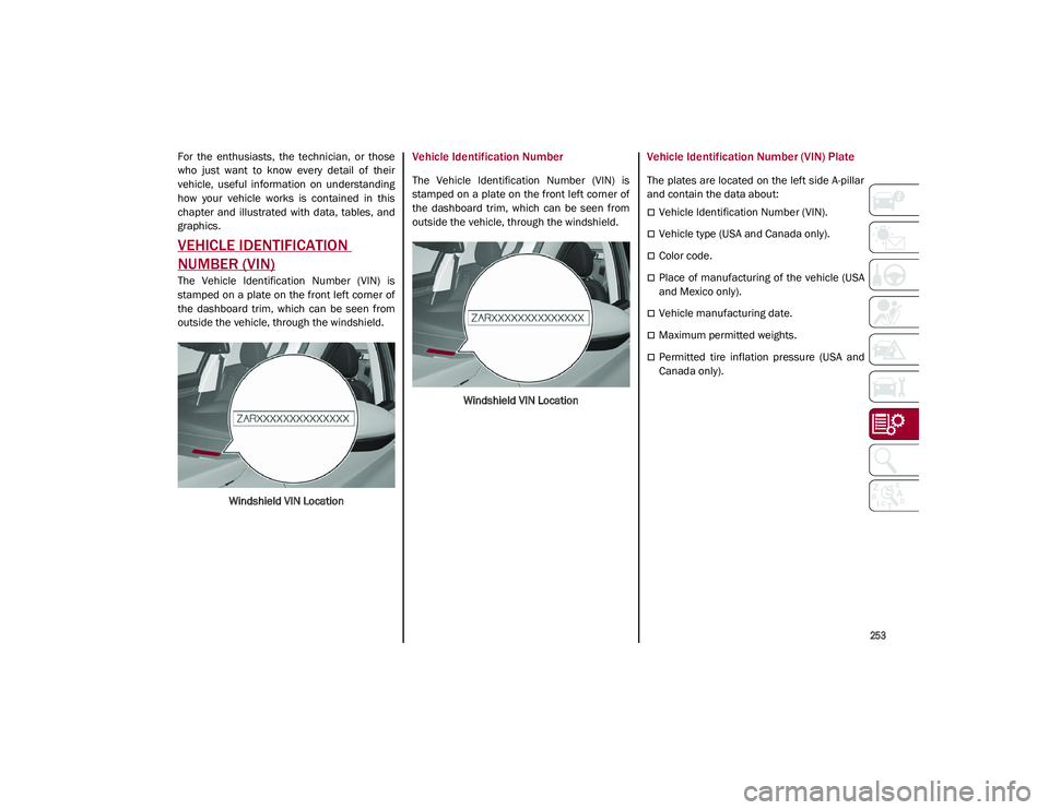
The Vehicle Identification Number (VIN) is
stamped on a plate on the front left corner of
the dashboard trim, which can be seen from
outside the vehicle, through the windshield.Windshield VIN Location
Vehicle Identification Number
The Vehicle Identification Number (VIN) is
stamped on a plate on the front left corner of
the dashboard trim, which can be seen from
outside the vehicle, through the windshield.Windshield VIN Location
Vehicle Identification Number (VIN) Plate
The plates are located on the left side A-pillar
and contain the data about:
Vehicle Identification Number (VIN).
Vehicle type (USA and Canada only).
Color code.
Place of manufacturing of the vehicle (USA
and Mexico only).
Vehicle manufacturing date.
Maximum permitted weights.
Permitted tire inflation pressure (USA and
Canada only).
21_GU_OM_EN_USC_t.book Page 253