2019 MERCEDES-BENZ SPRINTER tow
[x] Cancel search: towPage 223 of 354
Using the interior
roof car rier sy stem &
WARNING Risk of inju rydue tounse‐
cured loads
When you secure or loosen a load, the load
may fall down and injure vehicle occupants. #
When securing or loosening a load, do
not stand under the load. *
NO
TERisk of damage tothe belt stra ps
and slider Excessive point loading on
the belt stra ps and
sliders may cause the belt stra ps totear or cause
the sliders tobreak off from thera ck
ra il. #
Distribute the load evenly. When doing
so, ensure that theove rall cen ter of
gr av ity of the load is alw ays as close to
th e center as possible and between the
ro of rails and between thera ck rails. Yo
u can use the interior roof rack system to
secure loads. It is also suitable for securing long
loads.
% The interior
roof rack system may be subjec‐
te dto a maximum load of 110 lbs (50 kg).
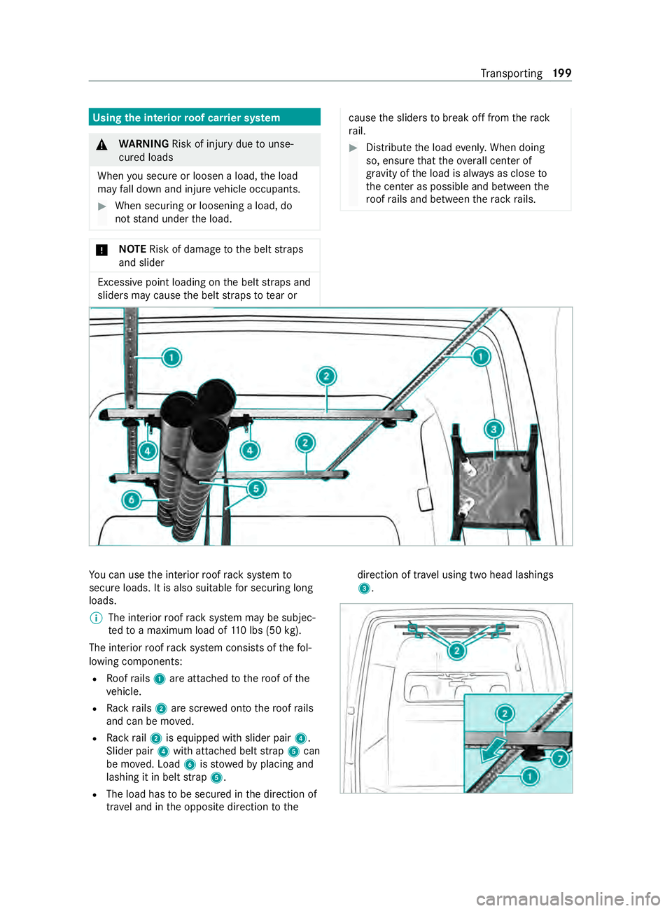
The interior roof rack system consists of thefo l‐
lowing components:
R Roofrails 1 are attached tothero of of the
ve hicle.
R Rack rails 2 are scr ewed onto thero of rails
and can be mo ved.
R Rack rail2 is equipped with slider pair 4.
Slider pair 4with attached belt stra p5 can
be mo ved. Load 6isstowe dby placing and
lashing it in belt stra p5.
R The load has tobe secured in the direction of
tra vel and in the opposite direction tothe direction of tra
vel using two head lashings
3. Tr
ansporting 19 9
Page 235 of 354
wa
sher and the associated spr aycould cause
considerable damage totheve hicle.
To avo id damage to yourvehicle, obser vethefo l‐
lowing when using a po werwa sher:
R maintain a minimum dis tance of 11.8 in
(30 cm) totheve hicle when using 25° flat-
spr aynozzles and di rtgrinders or 27.6 in
(70 cm) when using round-spray nozzles and
obse rveth e information in the equipment
manufacturer's operating instructions.
R do not direct the nozzle of the po werwa sher
directly at sensitive parts such as tires, slits,
electrical components, batteries, light bulbs
and ventilation slits.
R maintain a minimum di stance of 19.7 in
(50 cm) for a rear view camera. Wa
shing theve hicle byhand Obser
vethe legal requirements, forex ample in
many countries washing byhand is only allo wed
at specially designated wash ba ys. In this case,
make sure that a specially designated wash bay is
used forwa shing byhand. #
Use a mild cleaning agent, e.g. car shampoo. #
Washtheve hicle with luk ewarm wate r and a
soft car sponge. When doing so, do not
ex pose theve hicle todirect sunlight. #
Carefully spr aytheve hicle with water and dry
off with a leath er cloth. Be careful not to
point thewate r jet directly towa rdsth e air
inlet grilles. The blo wer should be switched
off while doing so. #
Do not let the cleaning agent dry on the paint‐
wo rk.
At the onset of winter, remo veall traces of road
salt deposits carefully and as soon as possible. Note
s on care of paint and matte finish *
NO
TEPaint wo rkdamage and cor rosion
due toinadequate care Fa
ilure toprom ptly and thoroughly remo ve
dirt from bird droppings or other residue
could result in paintwork damage and cor ro‐
sion at a later date. #
Clean dirt off paint and matte finish
th oroughly and as soon as possible. Maintenance and care
211
Page 240 of 354
Emer
gency Re
moving the saf etyve st The saf
etyve st is located in thestow age com‐
partment in the driver's door. #
Remo vethe saf etyve st from thestow age
compartment.
% Saf
etyve sts can also be stored in thestow‐
age compartments of there ar doors and the
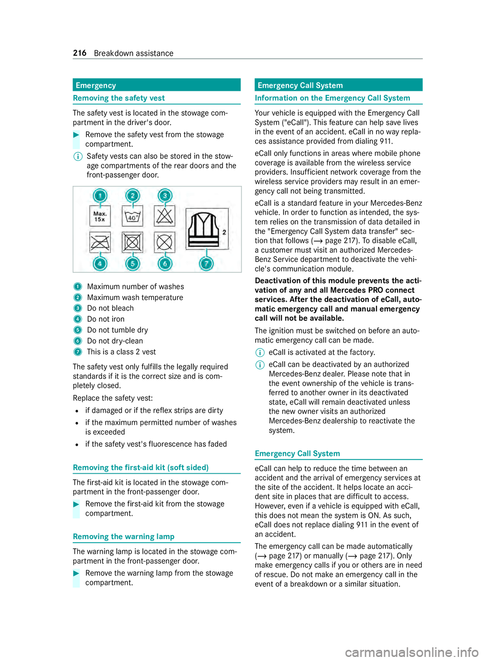
front-passenger door. 1
Maximum number of washes
2 Maximum wash temp erature
3 Do not bleach
4 Do not iron
5 Do not tumble dry
6 Do not dr y-clean
7 This is a class 2 vest
The saf etyve st only fulfills the legally required
st andards if it is the cor rect size and is com‐
ple tely closed.
Re place the saf etyve st:
R if damaged or if there flex strips are dirty
R ifth e maximum permitted number of washes
is exc eeded
R ifth e saf etyve st's fluorescence has faded Re
moving the firs t-aid kit (soft sided) The
firs t-aid kit is located in thestow age com‐
partment in the front-passenger door. #
Remo vethefirs t-aid kit from thestow age
compartment. Re
moving the warning lamp The
warning lamp is located in thestow age com‐
partment in the front-passenger door. #
Remo vethewa rning lamp from thestow age
compartment. Emer
gency Call Sy stem Information on
the Emer gency Call Sy stem Yo
ur vehicle is equipped with the Emer gency Call
Sy stem ("eCall"). This feature can help sa velives
in theeve nt of an accident. eCall in no wayre pla‐
ces assis tance pr ovided from dialing 911.
eCall only functions in areas where mobile phone
co verage isavailable from the wireless service
pr ov iders. Insuf ficient network co verage from the
wireless service pr oviders may result in an emer‐
ge ncy call not being transmitted.
eCall is a standard feature in your Mercedes-Benz
ve hicle. In order tofunction as intended, the sys‐
te m relies on the transmission of data de tailed in
th e "Emer gency Call Sy stem data transfer" sec‐
tion that follo ws ( /page 217). Todisable eCall,
a cus tomer must visit an authorized Mercedes-
Benz Service depa rtment todeactivate theve hi‐
cle's communication module.
Deactivation of this module pr events the acti‐
va tion of any and all Mercedes PRO connect
se rvices. Af ter the deacti vation of eCall, auto‐
matic eme rgency call and manual emer gency
call will not be available.
The ignition must be switched on before an auto‐
matic emer gency call can be made.
% eCall is acti
vated at thefa ctor y.
% eCall can be deactivated
byan authorized
Mercedes-Benz dealer. Please no tethat in
th eeve ntow nership of theve hicle is trans‐
fe rred toano ther ow ner in its deacti vated
st ate, eCall will remain deactivated unless
th e new owner visits an au thorized
Mercedes-Benz dealership toreactivate the
sy stem. Emer
gency Call Sy stem eCall can help
toreduce the time between an
accident and the ar riva l of emer gency services at
th e site of the accident. It helps locate an acci‐
dent site in places that are dif ficult toaccess.
Ho wever,eve n if a vehicle is equipped with eCall,
th is does not mean the sy stem is ON. As such,
eCall does not replace dialing 911 in theeve nt of
an accident.
The emergency call can be made au tomatical ly
( / page 217) or manually (/ page217). Only
make emergency calls if you or others are in need
of rescue. Do not make an emer gency call in the
eve nt of a breakdown or a similar situation. 216
Breakdown assis tance
Page 245 of 354

R
vehicles with a gasoline engine: only per‐
fo rm starting assis tance when the engine and
ex haust sy stem are cold #
Vehicles with a battery main switch: check
whe ther the battery main switch is switched
on (/ page114). #
Secu retheve hicle using the parking brake. #
Vehicles with automatic transmission:
shift the transmission toposition 005D. #
Switch off the ignition and all electrical con‐
sumers. #
Open the hood (/ page 202). Example: jump-s
tart connection point
% Right-hand-drive
vehicles: the jump-s tart
connection points may be on the opposite
side. #
Remo vethe co ver from the positive term inal
on the donor batter y. #
First, connect the positive term inal clamp of
th e jumper cables/charging cables tothe
positive term inal of theot her vehicle's bat‐
te ry. #
With positive term inal clamp 2ofthe
jumper cable, slide there d pr otective cap on
jump-s tart connection point 1back with a
clockwise turn. #
Connect the positive term inal clamp tothe
positive term inal of jump-s tart connection
point 1. #
During starting assistance: start the engine
of the donor vehicle and let it run at idle
speed. #
Connect the negative term inal of the donor
battery tothe ground point of your ow nve hi‐ cle with
the jumper cable/charging cable.
Begin with the donor batter y. #
During starting assistance: start the engine
on your ow nve hicle. #
When charging: start thech arging process. #
During starting assistance: letthe engine
ru nfo r a few minutes. #
During starting assistance: before discon‐
necting the jumper cable, switch on an elec‐
trical consumer on your ow nve hicle, e.g. the
re ar wind owheater or lighting.
When thest arting assis tance/charging process is
comple te: #
First,re mo vethe jumper cables/charging
cables from the ground point and negative
te rm inal of theot her vehicle's batter y,then
from the positive term inal of jump-s tart con‐
nection point 1and the positive term inal of
th eot her vehicle's batter y.Each time, begin
at the contacts on your ow nve hicle.
The red pr otective cap springs back toits ini‐
tial position when positive term inal clamp 2
is disconnected from jump-s tart connection
point 1.
Fu rther information can be obtained at a qualified
specialist workshop. Installing/removing
thefloor co vering (vehi‐
cles with rear wheel drive) &
WARNING Risk of accident due to
objects in the driver's foot we ll
Objects in the driver's foot we ll may impede
pedal tr avel or block a depressed pedal.
This jeopardizes the operating and road
saf ety of theve hicle. #
Stow all objects in theve hicle securely
so that they cannot getinto the driver's
fo ot we ll. #
Ensure floor mats and carpets cannot
slip and pr ovide suf ficient room forthe
pedals. #
Do not lay multiple floor mats or carpets
on top of one ano ther. Breakdown assis
tance 221
Page 248 of 354
Otherwise,
gases or battery acid could
escape.
R Make sure that the de tach able parts are con‐
nec ted in the same way as before. Disconnecting
the auxiliary bat tery inthe
engine compa rtment *
NO
TEDama getothe electrical assembly By disconnecting
thest ar ter battery before
th e engine is switched off and theke y is
re mo ved from the ignition loc k,electrical
assemblies could be damaged. #
Switch off the engine and remo vethe
ke y from the ignition loc k.Then, release
th e battery clamps of thest ar ter bat‐
te ry. #
Always disconnect thest ar ter battery in
th e battery case in the left foot we llfirs t.
Otherwise, electrical assemblies, e.g.
th e alternator, could be damaged. *
NO
TEDama getotheve hicle's electron‐
ics Incor
rectly disconnecting the auxiliary battery
can cause damage totheve hicle's electron‐
ics. #
Always disconnect the auxiliary battery
as described in thefo llowing sequence.
Do not reve rseth e battery term inals
under any circums tances. #
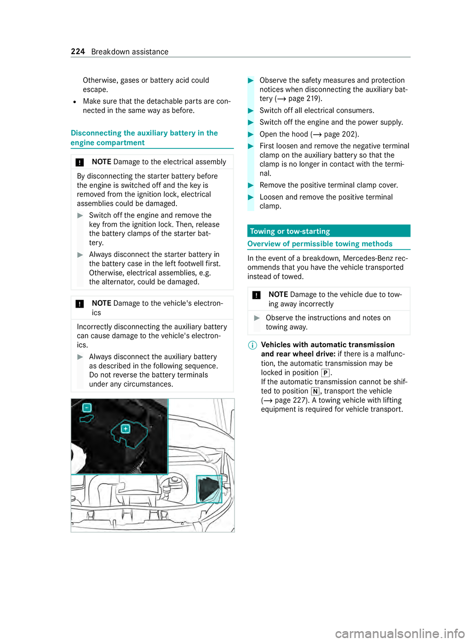
Obser vethe saf ety measures and pr otection
notices when disconnecting the auxiliary bat‐
te ry ( / page 219). #
Swit choff all electrical consumers. #
Switch off the engine and the po wer supp ly. #
Open the hood (/ page 202). #
Firstloosen and remo vethe negative term inal
clamp on the auxiliary battery so that the
cla mp is no longer in con tact wi th thete rm i‐
nal. #
Remo vethe positive term inal clamp co ver. #
Loosen and remo vethe positive term inal
clamp. To
wing or tow- starting Overview of permissible
towing me thods In
theeve nt of a breakdown, Mercedes-Benz rec‐
ommends that you ha vetheve hicle transpor ted
ins tead of towe d.
* NO
TEDama getotheve hicle due to tow‐
ing away incor rectly #
Obser vethe instructions and no tes on
to wing away. %
Ve
hicles with automatic transmission
and rear wheel drive: ifth ere is a malfunc‐
tion, the automatic transmission may be
loc ked in position 005D.
If th e automatic transmission cann otbe shif‐
te dto position 005C, transport theve hicle
(/ page 227). A towing vehicle with lifting
equipment is requ ired forve hicle transport. 224
Breakdown assis tance
Page 249 of 354
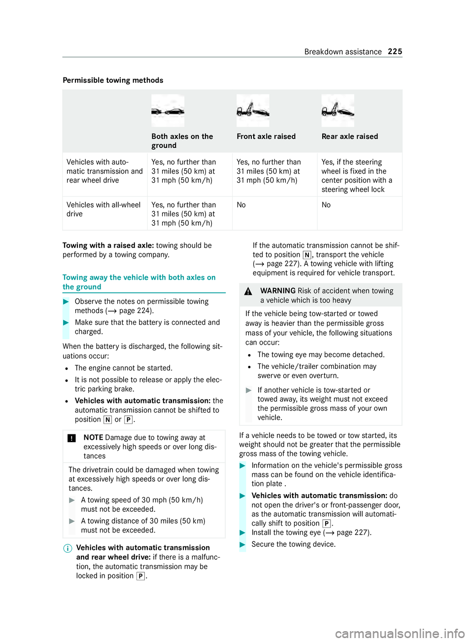
Pe
rm issible towing me thods Bo
th axles on the
gr ound Fr
ont axle raised Re
ar axle raised
Ve hicles with auto‐
matic transmission and
re ar wheel drive Ye
s, no fur ther than
31 miles (50 km) at
31 mp h (50 km/h) Ye
s, no fur ther than
31 miles (50 km) at
31 mp h (50 km/h) Ye
s, if thesteering
wheel is fixe d in the
center position wi th a
st eering wheel lock
Ve hicles with all-wheel
drive Ye
s, no fur ther than
31 miles (50 km) at
31 mp h (50 km/h) No
NoTo
wing with a raised axle: towing should be
per form ed byato wing compan y. To
wing away theve hicle with bo thaxles on
th egr ound #
Obser vethe no tes on permissible towing
me thods (/ page 224). #
Make sure that the battery is connected and
ch arge d.
When the battery is dischar ged, thefo llowing sit‐
uations occur:
R The engine cannot be star ted.
R It is not possible torelease or apply the elec‐
tric parking brake.
R Vehicles with automatic transmission: the
automatic transmission cannot be shif tedto
position 005Cor005D.
* NO
TEDama gedue to to wing away at
exc essively high speeds or over long dis‐
ta nces The driv
etra in could be damaged when towing
at exc essively high speeds or over long dis‐
ta nces. #
Atowing speed of 30 mph (50 km/h)
must not be exceeded. #
Atowing distance of 30 miles (50 km)
must not be exceeded. %
Ve
hicles with automatic transmission
and rear wheel drive: ifth ere is a malfunc‐
tion, the automatic transmission may be
loc ked in position 005D. If
th e automatic transmission cann otbe shif‐
te dto position 005C, transport theve hicle
(/ page 227). A towing vehicle with lifting
equipment is requ ired forve hicle transport. &
WARNING Risk of accident when towing
a ve hicle which is too heavy
If th eve hicle being tow- star ted or towed
aw ay is heavier than the permissible gross
mass of your vehicle, thefo llowing situations
can occur:
R The towing eye may become de tach ed.
R The vehicle/trailer combination may
swer veoreve nove rturn. #
If ano ther vehicle is tow- star ted or
to we daw ay, its weight must not exceed
th e permissible gross mass of your own
ve hicle. If a
vehicle needs tobe towe d or tow star ted, its
we ight should not be greaterth at the permissible
gross mass of theto wing vehicle. #
Information on theve hicle's permissible gross
mass can be found on theve hicle identifica‐
tion plate . #
Vehicles with automatic transmission: do
not open the driver's or front-passen ger door,
as the automatic transmission will automati‐
cally shift toposition 005D. #
Installth eto wing eye (/ page 227). #
Secure theto wing device. Breakdown assis
tance 225
Page 250 of 354
*
NO
TEDama gedue toincor rect connec‐
tion #
Only connect theto w rope or tow bar to
th eto wing eyes. %
Yo
u can also secure theto wing device tothe
trailer hitch.
* NO
TEDama geand risk of accident when
to wing with a tow rope There is a
risk of an accident if you do not
obse rve saf ety and pr otective measures when
to wing using a tow rope.
Obser vethefo llowing points when towing
with a tow rope: #
Secure theto w rope on the same side
on bo thvehicles, if possible. #
Make sure theto w rope does not
exc eed the legally prescribed length. #
Mark theto w rope in the middle, e.g.
with a white clo th(30 x 30 cm). This
makes other road users aware that a
ve hicle is being towe d. #
Obser vethe brake lamps of theto wing
ve hicle while driving. Alw ays maintain a
dis tance that ensures theto w rope does
not sag. #
Do not use steel cables or chains to tow
yo ur vehicle. Otherwise, you could dam‐
age theve hicle. #
Deactivate automatic locking (/ page 45).#
Do not activate the HOLD function. #
Deactivate theto w- aw ay alarm (/ page57). #
Deacti vate Active Brake Assi st (/ page 141). #
Vehicles with automatic transmission:
shift the automatic transmission toposition
005C. #
Release the parking brake. &
WARNING Risk of accident due tolimi‐
te d saf ety-re lated functions during the
to wing process
Saf ety-re lated functions are limited or no lon‐
ge rav ailable in thefo llowing situations:
R the ignition is switched off.
R the brake sy stem or po werst eering sys‐
te m is malfunctioning. R
the energy supply or the on-board electri‐
cal sy stem is malfunctioning.
When your vehicle is then towe daw ay, signifi‐
cantly more ef fort may be requ ired tosteer
and brake than is normally required. #
Use a tow bar. #
Make sure that thesteering wheel can
mo vefreely, before towing theve hicle
aw ay. *
NO
TEDama gedue toexc essive tractive
po wer If
yo u pull away sharpl y,the tractive po wer
may be too high and theve hicles could be
damaged. #
Pull away slowly and smoo thly. To
wing a vehicle with the front or rear axle
ra ised *
NO
TEDama gewhen the ignition is
switched on If
yo u lea vethe ignition switched on when
to wing theve hicle with the front or rear axle
ra ised, ESP ®
actuation can damage the brake
sy stem. #
The ignition must be switched off. *
NO
TEDama gedue toincor rect remo val
or ins tallation of the propeller shafts When ins
talling the propeller shafts, they can
be damaged if you do not use new sc rews.
Alw ays use new scr ews when ins talling the
propeller shafts.
Only ha vethe propeller shafts ins talled or
re mo vedby qualified, skilled personnel. %
If
th e front axle is damaged, raise theve hicle
at the front axle and if there ar axle is dam‐
aged, raise theve hicle at there ar axle.
% Ve
hicles with automatic transmission
and rear wheel drive: ifth ere is a malfunc‐
tion, the automatic transmission may be
loc ked in position 005D.
If th e automatic transmission cann otbe shif‐
te dto position 005C, transport theve hicle
(/ page 227). A towing vehicle with lifting
equipment is requ ired forve hicle transport. 226
Breakdown assis tance
Page 251 of 354
#
Obser vethe no tes on permissible towing
me thods (/ page 224). #
The propeller shafts tothe drive axles must
be remo ved if the maximum permissible tow‐
ing dis tance is exceeded. #
Vehicles with automatic transmission:
shift the automatic transmission toposition
005C. #
Release the parking brake. #
Switch off the ignition. Loading
theve hicle for transport #
Obser vethe no tes on towing away
( / page 225) (/ page 226). #
Connect theto w bar totheto wing eyeto load
th eve hicle. #
Vehicles with automatic transmission:
shift the automatic transmission toposition
005C.
% Ve
hicles with automatic transmission: in
th eeve nt of damage tothe electrics, the
automatic transmission may be loc ked in
position 005D.Toshift toposition 005C, provide
th e on-board electrical sy stem with po wer
( / page 219). #
Load theve hicle onto the transpor ter. #
Vehicles with automatic transmission:
shift the automatic transmission toposition
005D. #
Use the parking brake tosecure theve hicle
against rolling away. #
Only secure theve hicle bythe wheels.
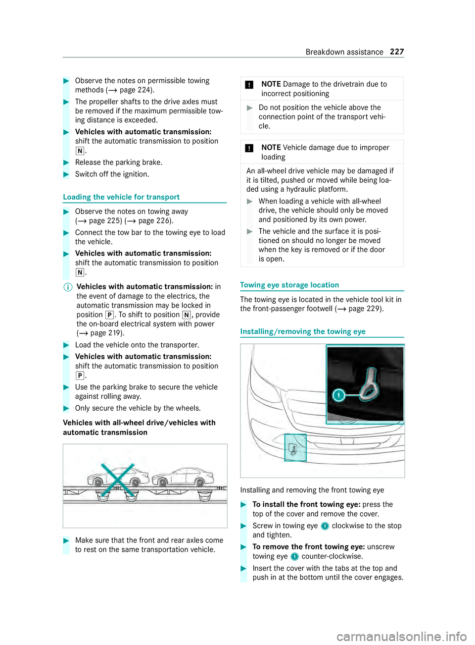
Ve hicles with all-wheel drive/vehicles with
automatic transmission #
Make sure that the front and rear axles come
to rest on the same transpor tation vehicle. *
NO
TEDama getothe driv etra in due to
incor rect positioning #
Do not position theve hicle abo vethe
connection point of the transport vehi‐
cle. *
NO
TEVehicle damage due toimproper
loading An all-wheel drive
vehicle may be damaged if
it is tilted, pushed or mo ved while being loa‐
ded using a hydraulic platform. #
When loading a vehicle with all-wheel
drive, theve hicle should only be mo ved
and positioned byits own po wer. #
The vehicle and the sur face it is posi‐
tioned on should no longer be mo ved
when theke y is remo ved or if the door
is open. To
wing eyesto rage location The
towing eye is located in theve hicle tool kit in
th e front-passen gerfo ot we ll (/ page 229). Installing/removing
theto wing eye Ins
talling and removing the front towing eye #
Toinstall the front towing eye: press the
to p of the co ver and remo vethe co ver. #
Screw intowing eye1clockwise tothestop
and tighten. #
Toremo vethe front towing eye: unsc rew
to wing eye1 counter-clockwise. #
Insert the co ver with theta bs at theto p and
push in at the bottom until the co ver engages. Breakdown assi
stance 227