2019 CITROEN RELAY Handbook (in English)
-
 1
1 -
 2
2 -
 3
3 -
 4
4 -
 5
5 -
 6
6 -
 7
7 -
 8
8 -
 9
9 -
 10
10 -
 11
11 -
 12
12 -
 13
13 -
 14
14 -
 15
15 -
 16
16 -
 17
17 -
 18
18 -
 19
19 -
 20
20 -
 21
21 -
 22
22 -
 23
23 -
 24
24 -
 25
25 -
 26
26 -
 27
27 -
 28
28 -
 29
29 -
 30
30 -
 31
31 -
 32
32 -
 33
33 -
 34
34 -
 35
35 -
 36
36 -
 37
37 -
 38
38 -
 39
39 -
 40
40 -
 41
41 -
 42
42 -
 43
43 -
 44
44 -
 45
45 -
 46
46 -
 47
47 -
 48
48 -
 49
49 -
 50
50 -
 51
51 -
 52
52 -
 53
53 -
 54
54 -
 55
55 -
 56
56 -
 57
57 -
 58
58 -
 59
59 -
 60
60 -
 61
61 -
 62
62 -
 63
63 -
 64
64 -
 65
65 -
 66
66 -
 67
67 -
 68
68 -
 69
69 -
 70
70 -
 71
71 -
 72
72 -
 73
73 -
 74
74 -
 75
75 -
 76
76 -
 77
77 -
 78
78 -
 79
79 -
 80
80 -
 81
81 -
 82
82 -
 83
83 -
 84
84 -
 85
85 -
 86
86 -
 87
87 -
 88
88 -
 89
89 -
 90
90 -
 91
91 -
 92
92 -
 93
93 -
 94
94 -
 95
95 -
 96
96 -
 97
97 -
 98
98 -
 99
99 -
 100
100 -
 101
101 -
 102
102 -
 103
103 -
 104
104 -
 105
105 -
 106
106 -
 107
107 -
 108
108 -
 109
109 -
 110
110 -
 111
111 -
 112
112 -
 113
113 -
 114
114 -
 115
115 -
 116
116 -
 117
117 -
 118
118 -
 119
119 -
 120
120 -
 121
121 -
 122
122 -
 123
123 -
 124
124 -
 125
125 -
 126
126 -
 127
127 -
 128
128 -
 129
129 -
 130
130 -
 131
131 -
 132
132 -
 133
133 -
 134
134 -
 135
135 -
 136
136 -
 137
137 -
 138
138 -
 139
139 -
 140
140 -
 141
141 -
 142
142 -
 143
143 -
 144
144 -
 145
145 -
 146
146 -
 147
147 -
 148
148 -
 149
149 -
 150
150 -
 151
151 -
 152
152 -
 153
153 -
 154
154 -
 155
155 -
 156
156 -
 157
157 -
 158
158 -
 159
159 -
 160
160 -
 161
161 -
 162
162 -
 163
163 -
 164
164 -
 165
165 -
 166
166 -
 167
167 -
 168
168 -
 169
169 -
 170
170 -
 171
171 -
 172
172 -
 173
173 -
 174
174 -
 175
175 -
 176
176 -
 177
177 -
 178
178 -
 179
179 -
 180
180 -
 181
181 -
 182
182 -
 183
183 -
 184
184 -
 185
185 -
 186
186 -
 187
187 -
 188
188 -
 189
189 -
 190
190 -
 191
191 -
 192
192 -
 193
193 -
 194
194 -
 195
195 -
 196
196 -
 197
197 -
 198
198 -
 199
199 -
 200
200 -
 201
201 -
 202
202 -
 203
203 -
 204
204 -
 205
205 -
 206
206 -
 207
207 -
 208
208 -
 209
209 -
 210
210 -
 211
211 -
 212
212 -
 213
213 -
 214
214 -
 215
215 -
 216
216 -
 217
217 -
 218
218 -
 219
219 -
 220
220 -
 221
221 -
 222
222 -
 223
223 -
 224
224 -
 225
225 -
 226
226 -
 227
227 -
 228
228 -
 229
229 -
 230
230 -
 231
231
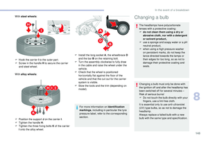
 143
With steel wheels:
With alloy wheels :
For more information on Identification
markings, including in particular the tyre
pressure label, refer to the corresponding
section.
F
H
ook the carri")
 144
In some weather conditions (e.g. low
temperature or humidity), the presence
of misting on the internal sur face of the
glass of the headlamps and rear lamps is
normal; it disappears after the")
 145
If necessary you can remove the headlamp
unit:
F
D
epending on country of sale, remove the
extreme cold protection foam by making it
slide sideways towards the outside.
F
D
isconnect the e")
 146
Direction indicator side
repeaters
Ty p e A , W16WF – 16W
F
M
ove the mirror glass to access the screws.
F
R
emove the two fixing screws.
F
P
ull the bulb holder to release it from th")
 147
Ty p e C , 12 V10W – 10W
Side marker lamps
Ty p e A , W5W – 5W
Courtesy lamps
F If your vehicle is fitted with these lamps
(L4 body), remove the two fixing screws.
F
P
ull the bulb h")
 148
Licence plate lamps
Ty p e C, C5W – 5W
F
P
ress the point indicated by the arrow, then
remove the plastic lens.
F
R
emove the failed bulb by moving aside the
two contacts.
F
W
ith th")
 149
Third brake lamp
Ty p e A, W5W – 5W (x 4)
F
R
emove the two lamp fixing screws.
F
R
emove the lamp by pulling it towards you.
F
R
emove the bulb holder by squeezing the
two tongues in")
 150
Dashboard, left-hand side,
fuses
F Remove the bolts and tilt the box to access the fuses. Fuses A (amps)
Allocation
12 7. 5Right-hand dipped headlamp
13 7. 5Left-hand dipped headlamp
31 5Engine c")