2018 MERCEDES-BENZ CLA COUPE ECU
[x] Cancel search: ECUPage 309 of 326
PSI (pounds per squareinch)
Astandard unit of measure for tire pressure.
Aspect ratio
Relationship between tire height and tire width
in percent.
Tire pressure
This is pressure inside the tire applying an out-
ward force to each square inch of the tire's sur-
face. The tire pressure is specified in pounds per
square inch (psi), in kilopascal (kPa) or in bar.
The tire pressure should only be corrected when
the tires are cold.
Cold tire pressure
The tires are cold:
Rif the vehicle has been parked with the tires
out of direct sunlight for at least three hours
and
Rif the vehicle has not been driven further than
1m ile (1.6 km)
Tread
The part of the tire that comes into contact with
the road.
Bead
The tire bead ensures that the tire sits securely
on the wheel. There are several steel wires in the
bead to prevent the tire from coming loose from
the wheel rim.
Sidewall
The part of the tire between the tread and the
bead.
Weight of optional extras
The combined weight of those optional extras
that weigh more than the replaced standard
parts and more than 2.3 kg (5 lbs). These
optional extras, such as high-performance
brakes, level control, aroof rack or ahigh-per-
formanceb attery, are not included in the curb
weight and the weight of the accessories.
TIN (Tire Identification Number)
This is aunique identifier which can be used by
at ire manufacturer to identify tires, for example
for aproduct recall, and thus identify the pur-
chasers. The TIN is made up of the manufactur-
er's identity code, tire size, tire type code and
the manufacturing date.
Load bearing index
The load bearing index (also load index) is acode
that contains the maximum load bearing capa-
city of atire.
Traction
Traction is the result of friction between the tires
and the road surface.
Treadwear indicators
Narrow bars (tread wear bars) that are distrib-
uted over the tire tread. If the tire tread is level
with the bars, the wear limit of áin (1.6 mm)
has been reached.
Occupant distribution
The distribution of occupants in avehicle at their
designated seating positions.
Total load limit
Nominal load and luggage load plus 68 kg
(15 0lbs)m ultiplied by the number of seats in
the vehicle.
Changing awheel
Flat tire
The "Breakdown assistance" section
(Ypage 271) contains information and notes on
how to deal with aflat tire. Information on driv-
ing with MOExtended tires in the event of aflat
tire can be found under "MOExtended tires (tires
with run-flat characteristics" (
Ypage 271).
Rotating the wheels
GWARNING
Interchanging the front and rear wheels may
severely impair the driving characteristics if
the wheels or tires have different dimensions. The wheel brakes or suspension components
may also be damaged. There is arisk of acci-
dent.
Rotate front and rear wheels only if the wheels and tires are of the same dimensions.
!On vehicles equippedw ithatire pressure
monitor ,electronic components are located
in the wheel.
Changing awheel307
Wheels and tires
Z
Page 311 of 326

Securing the vehicle to prevent it from
rolling away
If your vehicle is equippedwithaw heel chock,i t
can be found in the tire-change tool kit
(
Ypage 270).
The folding wheel chock is an additional safety
measure to prevent the vehicle from rolling
away,f or example when changing awheel.
XFold both plates up :.
XFold out lower plate ;.
XGuide the lugs on the lower plate fully into the
openings in base plate =.
XPlace chocksorother suitable items under
the front and rear of the wheel that is diago-
nally opposite the wheel you wish to change.
Raising the vehicle
GWARNING
If you do not position the jack correctly at the
appropriate jackingp oint of the vehicle, the
jack could tip over with the vehicle raised.
There is arisk of injury.
Only position the jack at the appropriate jack-
ing point of the vehicle. The base of the jack
must be positioned vertically, directly under
the jackingp oint of the vehicle.
!Only position the jack at the appropriate
jackingp oint of the vehicle. Otherwise, you
could damage the vehicle.
Observe the following when raising the vehi-
cle:
RTo raise the vehicle, only use the vehicle-spe-
cific jack that has been tested and approved
by Mercedes-Benz. If used incorrectly, the
jack could tip over with the vehicle raised.
RThe jack is designed only to raise and hold the
vehicle for ashort time while awheel is being
changed. It must not be used for performing
maintenance work under the vehicle.
RAvoid changing the wheel on uphill and down-
hill slopes.
RBefore raising the vehicle, secure it from roll-
ing away by applying the parking brake and
insertingw heel chocks. Do not disengage the
parking brake while the vehicle is raised.
RThe jack must be placed on afirm, flat and
non-slip surface. On aloose surface, alarge,
flat, load-bearing underlay must be used. On a
slippery surface, anon-slip underlay must be
used, e.g. rubber mats.
RDo not use wooden blocks or similar objects
as ajack underlay. Otherwise, the jack will not
be able to achieve its load-bearing capacity
due to the restricted height.
RMake sure that the distance between the
underside of the tires and the ground does not
exceed 1.2 in (3 cm).
RNever place your hands and feet under the
raised vehicle.
RDo not lie under the vehicle.
RDo not start the engine when the vehicle is
raised.
RDo not open or close adoor or the trunk lid
when the vehicle is raised.
RMake sure that no persons are present in the
vehicle when the vehicle is raised.
Changing awheel309
Wheels and tires
Z
Page 313 of 326
bolts to come loose. Asaresult, you could
lose awheel while driving .There is arisk of
accident.
Never oil or grease wheel bolts. In the event of
damage to the threads, contact aqualified
specialist workshop immediately. Have the
damaged wheel bolts or hub threads
replaced/renewed. Do not continue driving.
GWARNING
If you tighten the wheel bolts or wheel nuts
when the vehicle is raised, the jack could tip
over. There is arisk of injury.
Only tighten the wheel bolts or wheel nuts
when the vehicle is on the ground.
Always pay attention to the instructions and
safety notes in the "Changing awheel" section
(
Ypage 307).
Only use wheel bolts that have been designed
for the wheel and the vehicle. For safety rea-
sons, Mercedes-Benz recommends that you
only use wheel bolts which have been approved for Mercedes-Benz vehicles and the respective
wheel.
!To preventd amage to the paintwork, hold
the wheel securely against the wheel hub
while screwingint he first wheel bolt.
XClean the wheel and wheel hub contact sur-
faces.
XPlace the new wheel on the wheel hub and
push it on.
XTighten the wheel bolts until they are finger-
tight.
Lowering the vehicle
GWARNING
The wheels could work loose if the wheel nuts and bolts are not tightened to the specified
tightenin gtorque. There is arisk of accident.
Have the tightenin gtorque immediately
checked at aqualified specialist workshop
after awheel is changed.
XPlace the ratchet wrenc hontot he hexagon
nut of the jack so that the letters ABare visi-
ble.
XTurn the ratchet wrenc huntil the vehicle is
onc eagain standing firmly on the ground.
XPlace the jack to one side.
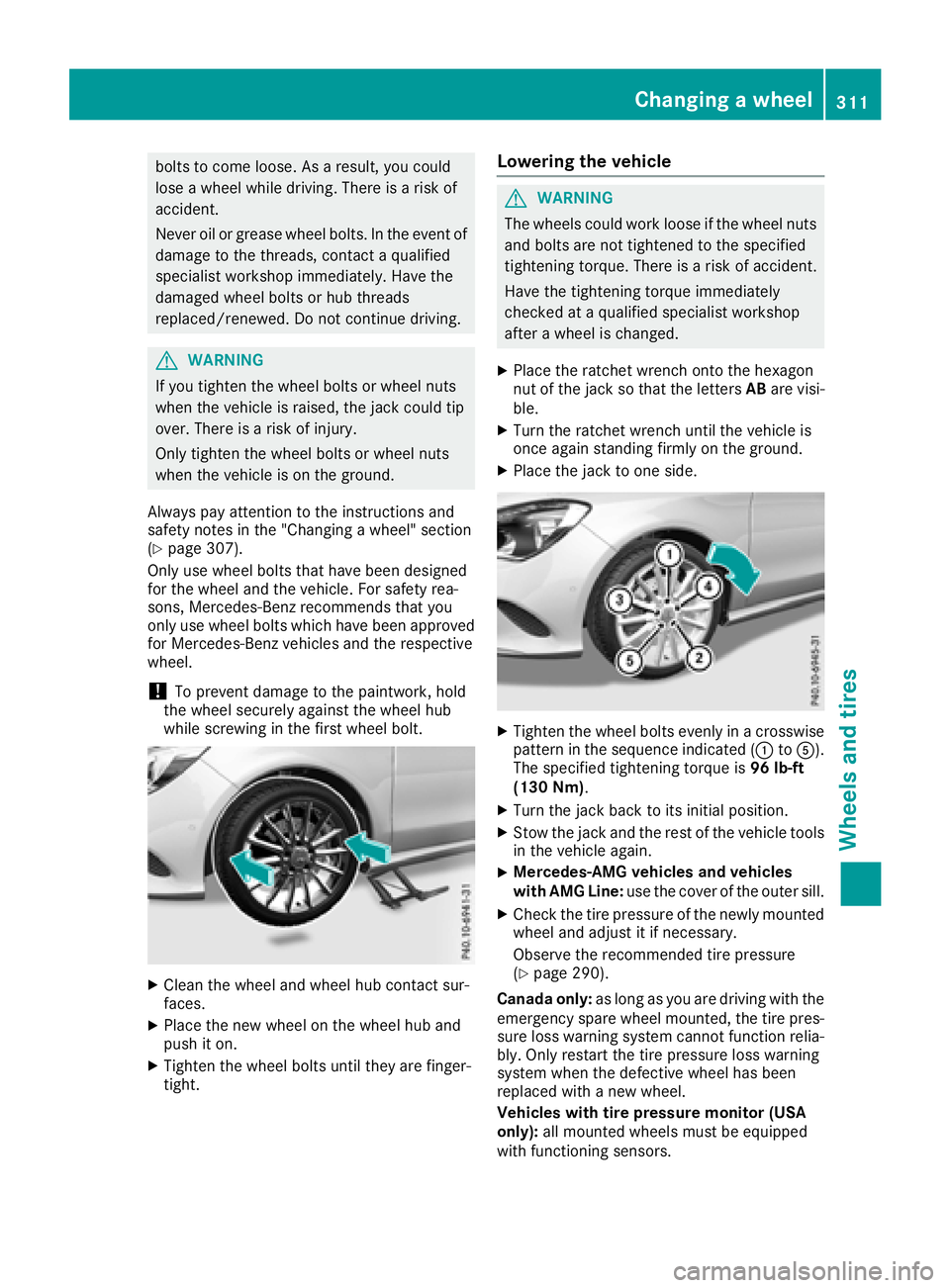
XTighten the wheel bolts evenly in acrosswise
pattern in the sequence indicated (: toA).
The specified tightenin gtorque is 96 lb-ft
(130 Nm) .
XTurn the jack back to its initial position.
XStow the jack and the rest of the vehicle tools
in the vehicle again.
XMercedes-AMG vehicles and vehicles
with AMG Line: use the cover of the outer sill.
XCheck the tire pressure of the newly mounted
wheel and adjust it if necessary.
Observe the recommended tire pressure
(
Ypage 290).
Canadao nly:as long as you are driving with the
emergency spare wheel mounted, the tire pres-
sure loss warning system cannot function relia-
bly. Only restart the tire pressure loss warning
system when the defective wheel has been
replaced with anew wheel.
Vehicles with tir epressure monitor (USA
only): all mounted wheels must be equipped
with functioning sensors.
Changing awheel311
Wheels and tires
Z