2016 NISSAN NOTE headlamp
[x] Cancel search: headlampPage 1754 of 3641

EXL-102
< REMOVAL AND INSTALLATION >
FRONT COMBINATION LAMP
REMOVAL AND INSTALLATION
FRONT COMBINATION LAMP
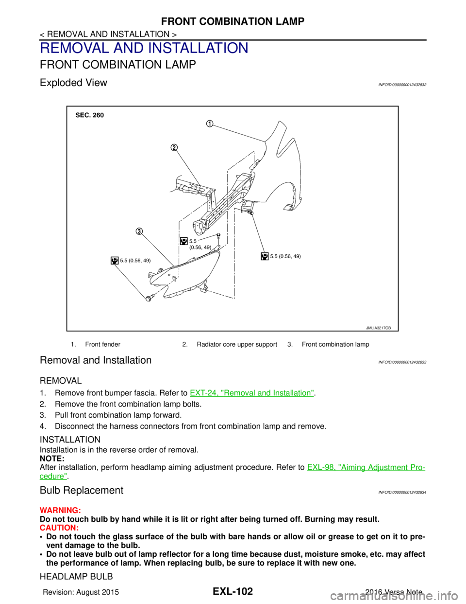
Exploded ViewINFOID:0000000012432832
Removal and InstallationINFOID:0000000012432833
REMOVAL
1. Remove front bumper fascia. Refer to EXT-24, "Removal and Installation".
2. Remove the front combination lamp bolts.
3. Pull front combination lamp forward.
4. Disconnect the harness connectors from front combination lamp and remove.
INSTALLATION
Installation is in the reverse order of removal.
NOTE:
After installation, perform headlamp aiming adjustment procedure. Refer to EXL-98, "
Aiming Adjustment Pro-
cedure".
Bulb ReplacementINFOID:0000000012432834
WARNING:
Do not touch bulb by hand while it is lit or right after being turned off. Burning may result.
CAUTION:
• Do not touch the glass surface of the bulb with bare hands or allow oil or grease to get on it to pre-
vent damage to the bulb.
• Do not leave bulb out of lamp reflector for a long time because dust, moisture smoke, etc. may affect
the performance of lamp. When replacing bulb, be sure to replace it with new one.
HEADLAMP BULB
1. Front fender2. Radiator core upper support 3. Front combination lamp
JMLIA3217GB
Revision: August 2015 2016 Versa Note
cardiagn.com
Page 1765 of 3641

FRONT COMBINATION LAMPEXL-113
< UNIT DISASSEMBLY AND ASSEMBLY >
C
DE
F
G H
I
J
K
M A
B
EXL
N
O P
UNIT DISASSEMBLY AND ASSEMBLY
FRONT COMBINATION LAMP
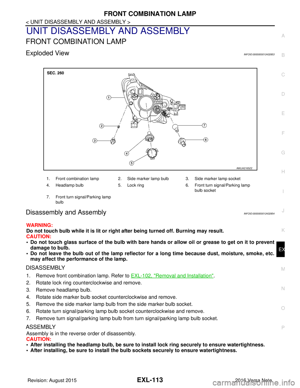
Exploded ViewINFOID:0000000012432853
Disassembly and AssemblyINFOID:0000000012432854
WARNING:
Do not touch bulb while it is lit or right after being turned off. Burning may result.
CAUTION:
• Do not touch glass surface of the bulb with bare hands or allow oil or grease to get on it to prevent damage to bulb.
• Do not leave the bulb out of the lamp reflector for a long time because dust , moisture, smoke, etc.
may affect the performance of the lamp.
DISASSEMBLY
1. Remove front combination lamp. Refer to EXL-102, "Removal and Installation".
2. Rotate lock ring counterclockwise and remove.
3. Remove headlamp bulb.
4. Rotate side marker bulb socket counterclockwise and remove.
5. Remove the side marker lamp bulb from the side marker bulb socket.
6. Rotate turn signal/parking lamp bulb socket counterclockwise and remove.
7. Remove turn signal/parking lamp bulb from turn signal/parking lamp bulb socket.
ASSEMBLY
Assembly is in the reverse order of disassembly.
CAUTION:
• After installing the headlamp bulb, be sure to install lock ring securely to ensure watertightness.
• After installing, be sure to install the bulb sockets securely to ensure watertightness.
1. Front combination lamp 2. Side marker lamp bulb 3. Side marker lamp socket
4. Headlamp bulb 5. Lock ring 6. Front turn signal/Parking lamp
bulb socket
7. Front turn signal/Parking lamp bulb
AWLIA2165ZZ
Revision: August 2015 2016 Versa Note
cardiagn.com
Page 1767 of 3641

SERVICE DATA AND SPECIFICATIONS (SDS)EXL-115
< SERVICE DATA AND SPECIFICATIONS (SDS)
C
DE
F
G H
I
J
K
M A
B
EXL
N
O P
SERVICE DATA AND SPECIFICATIONS (SDS)
SERVICE DATA AND SPECIFICATIONS (SDS)
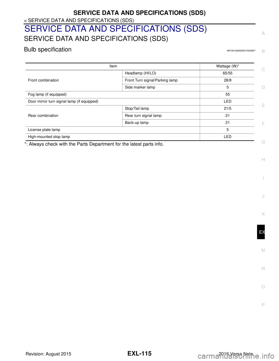
Bulb specificationINFOID:0000000012432857
*: Always check with the Parts Department for the latest parts info.
Item Wattage (W)*
Front combination Headlamp (HI/LO)
65/55
Front Turn signal/Parking lamp 28/8
Side marker lamp 5
Fog lamp (if equipped) 55
Door mirror turn signal lamp (if equipped) LED
Rear combination Stop/Tail lamp
21/5
Rear turn signal lamp 21
Back-up lamp 21
License plate lamp 5
High-mounted stop lamp LED
Revision: August 20152016 Versa Note
cardiagn.com
Page 2198 of 3641
![NISSAN NOTE 2016 Service Repair Manual LAN-10
< SYSTEM DESCRIPTION >[CAN FUNDAMENTAL]
TROUBLE DIAGNOSIS
Symptom When Error Occurs in CAN Communication System
INFOID:0000000012433334
In CAN communication system, multiple control units mutu NISSAN NOTE 2016 Service Repair Manual LAN-10
< SYSTEM DESCRIPTION >[CAN FUNDAMENTAL]
TROUBLE DIAGNOSIS
Symptom When Error Occurs in CAN Communication System
INFOID:0000000012433334
In CAN communication system, multiple control units mutu](/manual-img/5/57363/w960_57363-2197.png)
LAN-10
< SYSTEM DESCRIPTION >[CAN FUNDAMENTAL]
TROUBLE DIAGNOSIS
Symptom When Error Occurs in CAN Communication System
INFOID:0000000012433334
In CAN communication system, multiple control units mutually transmit and receive signals. Each control unit
cannot transmit and receive signals if any error occurs on CAN communication line. Under this condition, mul-
tiple control units related to the root cause malfunction or go into fail-safe mode.
ERROR EXAMPLE
NOTE:
Each vehicle differs in symptom of each control unit under fail-safe mode and CAN communication line wiring.
Example: Main Line Between Data Link Connector and ABS Actuator and Electric Un it (Control Unit) Open Circuit
JSMIA0442GB
Unit name Major symptom
ECM Engine torque limiting is affected, and shift harshness increases.
BCM • Reverse warning buzzer does not sound.
• The front wiper moves under continuous operation mode even though the front wip-
er switch being in the intermittent position.
EPS control unit The steering effort increases.
Combination meter • The shift position indicator and OD OFF indicator turn OFF.
• The speedometer is inoperative.
• The odo/trip meter stops.
ABS actuator and electric unit (control unit) Normal operation.
TCM No impact on operation.
IPDM E/R When the ignition switch is ON,
• The headlamps (Lo) turn ON.
• The cooling fan continues to rotate.
Revision: August 2015
2016 Versa Note
cardiagn.com
Page 2200 of 3641
![NISSAN NOTE 2016 Service Repair Manual LAN-12
< SYSTEM DESCRIPTION >[CAN FUNDAMENTAL]
TROUBLE DIAGNOSIS
NOTE:
When data link connector branch line is open, transmiss
ion and reception of CAN communication signals are
not affected. Therefor NISSAN NOTE 2016 Service Repair Manual LAN-12
< SYSTEM DESCRIPTION >[CAN FUNDAMENTAL]
TROUBLE DIAGNOSIS
NOTE:
When data link connector branch line is open, transmiss
ion and reception of CAN communication signals are
not affected. Therefor](/manual-img/5/57363/w960_57363-2199.png)
LAN-12
< SYSTEM DESCRIPTION >[CAN FUNDAMENTAL]
TROUBLE DIAGNOSIS
NOTE:
When data link connector branch line is open, transmiss
ion and reception of CAN communication signals are
not affected. Therefore, no symptoms occur. However, be sure to repair malfunctioning circuit.
Example: CAN-H, CAN-L Harness Short Circuit
CAN Diagnosis with CONSULTINFOID:0000000012433335
CAN diagnosis on CONSULT extracts the root c ause by receiving the following information.
Unit name Major symptom
ECM
Normal operation.
BCM
EPS control unit
Combination meter
ABS actuator and electric unit (control unit)
TCM
IPDM E/R
JSMIA0445GB
Unit name
Major symptom
ECM • Engine torque limiting is affected, and shift harshness increases.
• Engine speed drops.
BCM • Reverse warning buzzer does not sound.
• The front wiper moves under continuous operation mode even though the front
wiper switch being in the intermittent position.
• The room lamp does not turn ON.
• The engine does not start (if an error or malfunction occurs while turning the igni- tion switch OFF.)
• The steering lock does not release (if an error or malfunction occurs while turning the ignition switch OFF.)
EPS control unit The steering effort increases.
Combination meter • The tachometer and the speedometer do not move.
• Warning lamps turn ON.
• Indicator lamps do not turn ON.
ABS actuator and electric unit (control unit) Normal operation.
TCM No impact on operation.
IPDM E/R When the ignition switch is ON,
• The headlamps (Lo) turn ON.
• The cooling fan continues to rotate.
Revision: August 2015
2016 Versa Note
cardiagn.com
Page 2320 of 3641

GENERAL MAINTENANCEMA-5
< PERIODIC MAINTENANCE >
C
DE
F
G H
I
J
K L
M B
MA
N
O A
PERIODIC MAINTENANCE
GENERAL MAINTENANCE
Explanation of Gene
ral MaintenanceINFOID:0000000012432243
General maintenance includes those items which shoul d be checked during the normal day-to-day operation
of the vehicle. They are essential if the vehicle is to continue operati ng properly. The owners can perform the
checks and inspections themselves or they can have their NISSAN dealers do them.
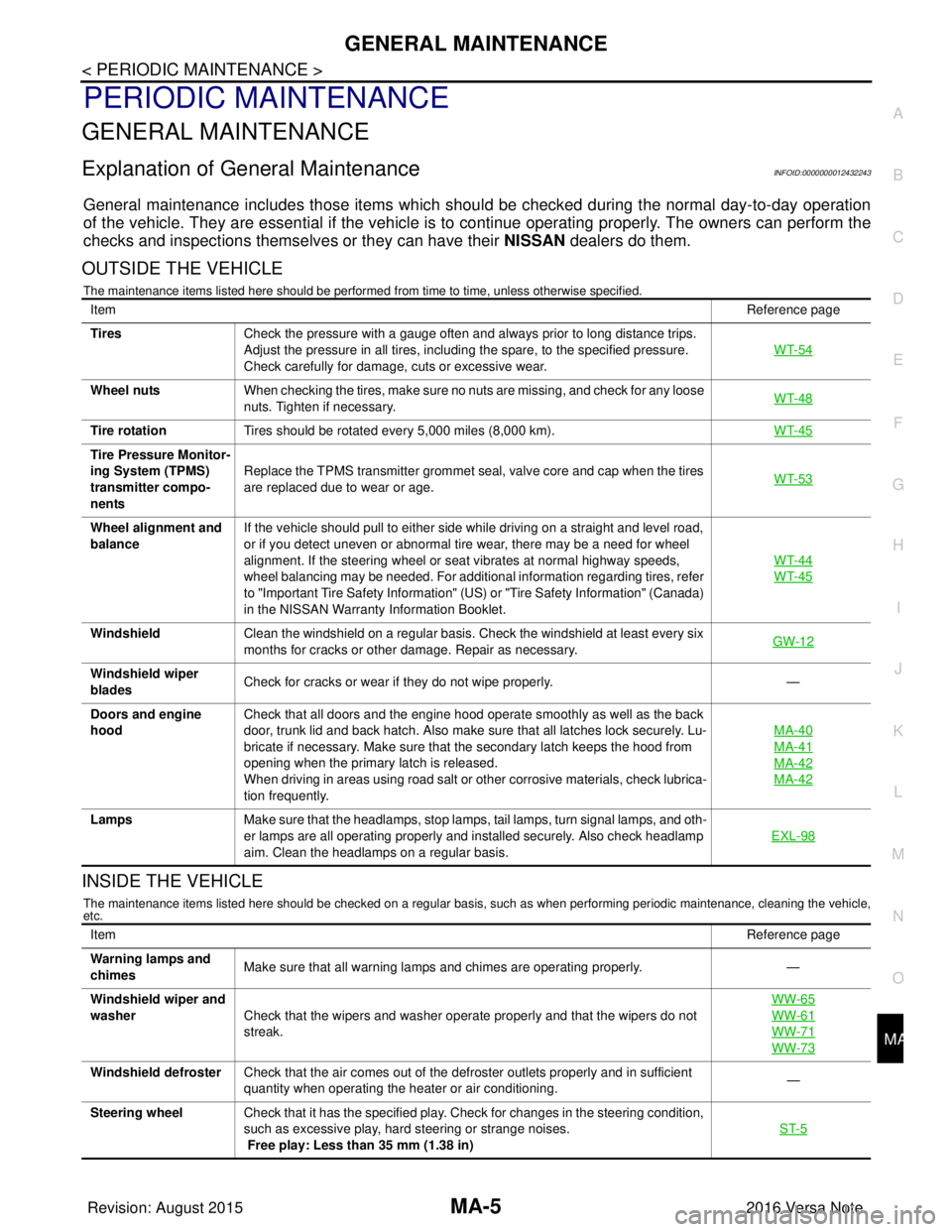
OUTSIDE THE VEHICLE
The maintenance items listed here should be performed from time to time, unless otherwise specified.
INSIDE THE VEHICLE
The maintenance items listed here should be checked on a regular basis, such as when performing periodic maintenance, cleaning the vehicle,
etc.
Item Reference page
Tires Check the pressure with a gauge often and always prior to long distance trips.
Adjust the pressure in all tires, including the spare, to the specified pressure.
Check carefully for damage, cuts or excessive wear. WT-54
Wheel nuts
When checking the tires, make sure no nuts are missing, and check for any loose
nuts. Tighten if necessary. WT-48
Tire rotation
Tires should be rotated every 5,000 miles (8,000 km). WT-45
Tire Pressure Monitor-
ing System (TPMS)
transmitter compo-
nentsReplace the TPMS transmitter grommet seal, valve core and cap when the tires
are replaced due to wear or age.
WT-53
Wheel alignment and
balanceIf the vehicle should pull to either side while driving on a straight and level road,
or if you detect uneven or abnormal tire wear, there may be a need for wheel
alignment. If the steering wheel or seat vibrates at normal highway speeds,
wheel balancing may be needed. For additional information regarding tires, refer
to "Important Tire Safety Information" (US) or "Tire Safety Information" (Canada)
in the NISSAN Warranty
Information Booklet. WT-44
WT-45
Windshield
Clean the windshield on a regular basis. Check the windshield at least every six
months for cracks or other damage. Repair as necessary. GW-12
Windshield wiper
bladesCheck for cracks or wear if they do not wipe properly.
—
Doors and engine
hood Check that all doors and the engine hood operate smoothly as well as the back
door, trunk lid and back hatch. Also make sure that all latches lock securely. Lu-
bricate if necessary. Make sure that the secondary latch keeps the hood from
opening when the primary latch is released.
When driving in areas using road salt or other corrosive materials, check lubrica-
tion frequently. MA-40
MA-41
MA-42
MA-42
Lamps
Make sure that the headlamps, stop lamps, tail lamps, turn signal lamps, and oth-
er lamps are all operating properly and installed securely. Also check headlamp
aim. Clean the headlamps on a regular basis. EXL-98
Item
Reference page
Warning lamps and
chimes Make sure that all warning lamps and chimes are operating properly.
—
Windshield wiper and
washer Check that the wipers and washer operate properly and that the wipers do not
streak. WW-65
WW-61
WW-71
WW-73
Windshield defroster
Check that the air comes out of the defroster outlets properly and in sufficient
quantity when operating the heater or air conditioning. —
Steering wheel Check that it has the specified play. Check for changes in the steering condition,
such as excessive play, hard steering or strange noises.
Free play: Less than 35 mm (1.38 in) ST-5
Revision: August 2015
2016 Versa Note
cardiagn.com
Page 2509 of 3641
![NISSAN NOTE 2016 Service Repair Manual PCS-6
< SYSTEM DESCRIPTION >[IPDM E/R]
SYSTEM
RELAY CONTROL SYSTEM : Fail-safe
INFOID:0000000012433269
CAN COMMUNICATION CONTROL
When CAN communication with ECM and BCM is impossible, IPDM E/R perform NISSAN NOTE 2016 Service Repair Manual PCS-6
< SYSTEM DESCRIPTION >[IPDM E/R]
SYSTEM
RELAY CONTROL SYSTEM : Fail-safe
INFOID:0000000012433269
CAN COMMUNICATION CONTROL
When CAN communication with ECM and BCM is impossible, IPDM E/R perform](/manual-img/5/57363/w960_57363-2508.png)
PCS-6
< SYSTEM DESCRIPTION >[IPDM E/R]
SYSTEM
RELAY CONTROL SYSTEM : Fail-safe
INFOID:0000000012433269
CAN COMMUNICATION CONTROL
When CAN communication with ECM and BCM is impossible, IPDM E/R performs fail-safe control. After CAN
communication recovers normally, it also returns to normal control.
If No CAN Communication Is Available With ECM
If No CAN Communication Is Available With BCM
Control relay Input/outputTransmit unit Control part Reference page
• Headlamp low relay
• Headlamp high relay • Low beam request signal
• High beam request signal
BCM (CAN)
• Headlamp LO
• Headlamp HI EXL-8
Tail lamp relay
Position light request signal BCM (CAN) •Parking lamp
• Side marker lamp
• License plate lamp
• Tail lamp
EXL-11
Illuminations
INL-9
• Front wiper relay
• Front wiper high relayFront wiper request signal BCM (CAN)
Front wiper motorWW-8Front wiper stop position sig-
nal Front wiper motor
Starter control relay Starter control relay signal BCM (CAN)
Starter motorSTR-8
(without Intelli-
gent Key)
STR-9
(with Intelligent
Key)
Transmission range switch
signal (CVT models)
Transmission range
switch
Clutch interlock switch signal
(M/T models) Clutch interlock switch
• Cooling fan low relay
• Cooling fan high relay Cooling fan speed request sig-
nal
ECM (CAN)
Cooling fan EC-38
A/C relayA/C compressor request sig-
nal
ECM (CAN)A/C compressor
(Magnet clutch)
HAC-11
Ignition relay-1Ignition switch ON signal BCM (CAN)
Each control unit,
sensor, actuator and
relay (Ignition power
supply) EC-35Vehicle speed signal (Meter)
Combination meter
(CAN)
Push-button ignition switch
signal Push-button ignition
switch
Control part
Fail-safe operation
Cooling fan • The cooling fan relay turn ON when the ignition switch is turned ON (Cooling fan HI operation)
• The cooling fan relay turn OFF when the ignition switch is turned OFF
A/C compressor A/C relay OFF
Generator Outputs the power generation command signal (PWM signal) 0%
Control part Fail-safe operation
Headlamp • Turns ON the headlamp low relay when the ignition switch is turned ON
• Turns OFF the headlamp low relay when the ignition switch is turned OFF
• Headlamp high relay OFF
•Parking lamp
• Side marker lamp
• License plate lamp
• Illumination
• Tail lamp • Turns ON the tail lamp relay when the ignition switch is turned ON
• Turns OFF the tail lamp relay when the ignition switch is turned OFF
Revision: August 2015
2016 Versa Note
cardiagn.com
Page 2512 of 3641
![NISSAN NOTE 2016 Service Repair Manual PCS
DIAGNOSIS SYSTEM (IPDM E/R)PCS-9
< SYSTEM DESCRIPTION > [IPDM E/R]
C
D
E
F
G H
I
J
K L
B A
O P
N
DIAGNOSIS SYSTEM (IPDM E/R)
Diagnosis DescriptionINFOID:0000000012433271
AUTO ACTIVE TEST
Descripti NISSAN NOTE 2016 Service Repair Manual PCS
DIAGNOSIS SYSTEM (IPDM E/R)PCS-9
< SYSTEM DESCRIPTION > [IPDM E/R]
C
D
E
F
G H
I
J
K L
B A
O P
N
DIAGNOSIS SYSTEM (IPDM E/R)
Diagnosis DescriptionINFOID:0000000012433271
AUTO ACTIVE TEST
Descripti](/manual-img/5/57363/w960_57363-2511.png)
PCS
DIAGNOSIS SYSTEM (IPDM E/R)PCS-9
< SYSTEM DESCRIPTION > [IPDM E/R]
C
D
E
F
G H
I
J
K L
B A
O P
N
DIAGNOSIS SYSTEM (IPDM E/R)
Diagnosis DescriptionINFOID:0000000012433271
AUTO ACTIVE TEST
Description
In auto active test, the IPDM E/R
sends a drive signal to the following systems to check their operation:
• Front wiper (LO, HI)
• Parking lamp
• Side marker lamp
• License plate lamp
• Tail lamp
• Front fog lamp
• Headlamp (LO, HI)
• A/C compressor (magnet clutch)
• Cooling fan
Operation Procedure
NOTE:
Never perform auto active test in the following conditions:
• Passenger door is open
• CONSULT is connected
1. Close the hood and lift the wiper arms from the windshield. (Prevent windshield damage due to wiper
operation)
NOTE:
When auto active test is performed with hood opened, sprinkle water on windshield beforehand.
2. Turn the ignition switch OFF.
3. Turn the ignition switch ON, and within 20 seconds, pr ess the driver door switch 10 times. Then turn the
ignition switch OFF.
4. Turn the ignition switch ON within 10 seconds. Af ter that the horn sounds once and the auto active test
starts.
5. After a series of the following operations is repeated 3 times, auto active test is completed.
NOTE:
• When auto active test has to be cancelled halfw ay through test, turn the ignition switch OFF.
• When auto active test is not activated, door swit ch may be the cause. Check door switch. Refer to DLK-98,
"ComponentFunctionCheck" (with Intelligent Key system) or DLK-232, "ComponentFunctionCheck"
(without Intelligent Key system).
Inspection in Auto Active Test
When auto active test is actuated, the following operation sequence is repeated 3 times.
Operation se-
quence Inspection location
Operation
1 Front wiper LO for 5 seconds → HI for 5 seconds
2 •Parking lamp
• Side marker lamp
• License plate lamp
• Tail lamp
• Front fog lamp (if equipped) 10 seconds
3 Headlamp LO for 10 seconds →HI ON ⇔ OFF 5 times
4 A/C compressor (magnet clutch) ON ⇔ OFF 5 times
5 Cooling fan LO for 5 seconds → MID for 3 seconds → HI for 2 seconds
Revision: August 2015 2016 Versa Note
cardiagn.com