2016 NISSAN NOTE headlamp
[x] Cancel search: headlampPage 1660 of 3641
EXL-8
< SYSTEM DESCRIPTION >
SYSTEM
SYSTEM
HEADLAMP SYSTEM
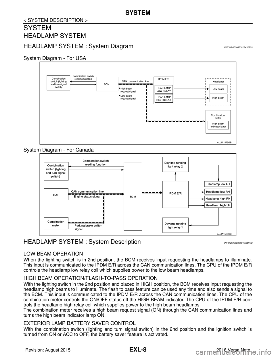
HEADLAMP SYSTEM : System Diagram INFOID:0000000012432769
System Diagram - For USA
System Diagram - For Canada
HEADLAMP SYSTEM : System DescriptionINFOID:0000000012432770
LOW BEAM OPERATION
When the lighting switch is in 2nd position, the BCM receives input requesting the headlamps to illuminate.
This input is communicated to the IPDM E/R across the CAN communication lines. The CPU of the IPDM E/R
controls the headlamp low relay coil which supplies power to the low beam headlamps.
HIGH BEAM OPERATION/FLASH-TO-PASS OPERATION
With the lighting switch in the 2nd position and placed in HIGH position, the BCM receives input requesting the
headlamp high beams to illuminate. The flash to pass f eature can be used any time and also sends a signal to
the BCM. This input is communicated to the IPDM E/R across the CAN communication lines. The CPU of the
combination meter controls the ON/OFF status off the HIGH BEAM indicator. The CPU of the IPDM E/R con-
trols the headlamp high relay coil which supplies power to the high beam headlamps.
The combination meter receives a high beam request signal (ON) through the CAN communication lines and
turns the high beam indicator lamp ON.
EXTERIOR LAMP BATTERY SAVER CONTROL
With the combination switch (lighting and turn signal switch) in the 2nd position and the ignition switch is
turned from ON or ACC to OFF, the battery saver feature is activated.
ALLIA1579GB
ALLIA1580GB
Revision: August 2015 2016 Versa Note
cardiagn.com
Page 1661 of 3641
SYSTEMEXL-9
< SYSTEM DESCRIPTION >
C
DE
F
G H
I
J
K
M A
B
EXL
N
O P
Under this condition, the headlamps remain illuminated for 45 seconds unless the lighting switch position is
changed. If the lighting switch position is changed, then the headlamps are turned off.
This setting can be changed by CONSULT. Refer to BCS-20, "
HEADLAMP : CONSULT Function (BCM -
HEAD LAMP)" (with Intelligent Key system) or BCS-93, "HEADLAMP : CONSULT Function (BCM - HEAD
LAMP)" (without Intelligent Key system).
DAYTIME RUNNING LIGHT SYSTEM
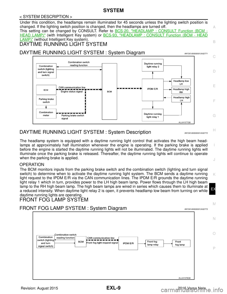
DAYTIME RUNNING LIGHT SYSTEM : System DiagramINFOID:0000000012432771
DAYTIME RUNNING LIGHT SYST EM : System DescriptionINFOID:0000000012432772
The headlamp system is equipped with a daytime running light control that activates the high beam head-
lamps at approximately half illumination whenever the e ngine is operating. If the parking brake is applied
before the engine is started the daytime running lights will not be illuminated. The daytime running lights will
illuminate once the parking brake is released. Thereaf ter, the daytime running lights will continue to operate
when the parking brake is applied.
OPERATION
The BCM monitors inputs from the parking brake swit ch and the combination switch (lighting and turn signal
switch) to determine when to activate the daytime running light system. The BCM sends a daytime running
light request to the IPDM E/R via the CAN communication lines. The IPDM E/R grounds the daytime running
light relay 1 which in turn, provides power to the LH high beam lamp. Power flows through the LH high beam
lamp to the RH high beam lamp. The high beam lamps are wired in series which causes them to illuminate at
a reduced intensity. When daytime light relay 2 is open, it prevents headlamp low beam from turning on while
daytime running lights are operating.
FRONT FOG LAMP SYSTEM
FRONT FOG LAMP SYSTEM : System DiagramINFOID:0000000012432773
ALLIA1577GB
ALLIA1578GB
Revision: August 2015 2016 Versa Note
cardiagn.com
Page 1662 of 3641
EXL-10
< SYSTEM DESCRIPTION >
SYSTEM
FRONT FOG LAMP SYSTEM : System Description
INFOID:0000000012432774
FRONT FOG LAMP OPERATION
When the combination switch (lighting and turn signal switch) is in front fog lamp ON position and also in 1ST
or 2ND position (headlamp is ON), the BCM detects FR FOG ON and the HEAD LAMP 1 or 2 ON. The BCM
sends a front fog lamp request ON signal through the CAN communication lines to the IPDM E/R. The IPDM
E/R then turns ON the front fog lamp relay sending power to the front fog lamps.
TURN SIGNAL AND HAZARD WARNING LAMP SYSTEM
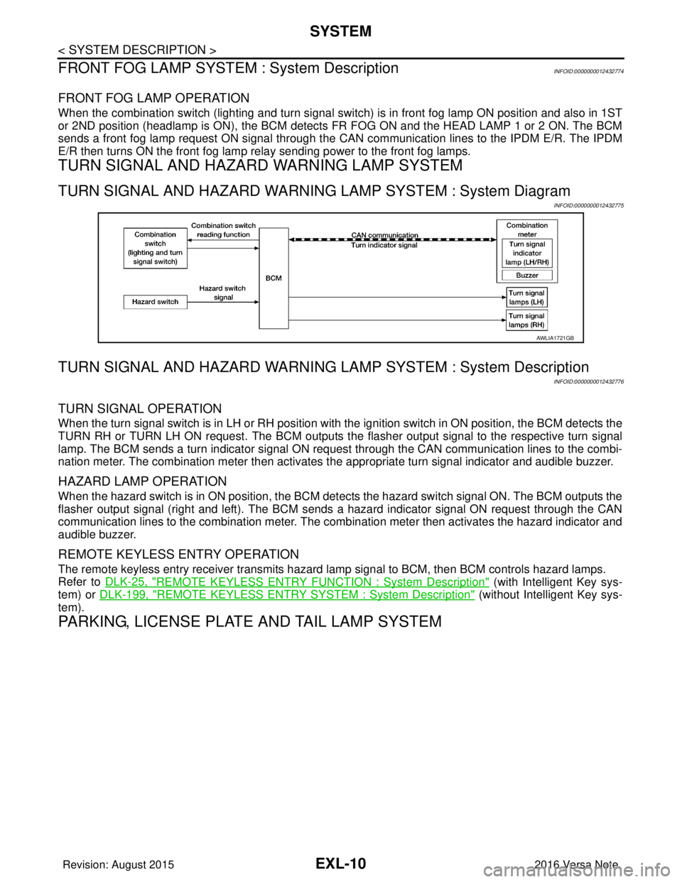
TURN SIGNAL AND HAZARD WARNING LAMP SYSTEM : System Diagram
INFOID:0000000012432775
TURN SIGNAL AND HAZARD WARNING LA MP SYSTEM : System Description
INFOID:0000000012432776
TURN SIGNAL OPERATION
When the turn signal switch is in LH or RH position with the ignition switch in ON position, the BCM detects the
TURN RH or TURN LH ON request. The BCM outputs the flasher output signal to the respective turn signal
lamp. The BCM sends a turn indicator signal ON request through the CAN communication lines to the combi-
nation meter. The combination meter then activates the appropriate turn signal indicator and audible buzzer.
HAZARD LAMP OPERATION
When the hazard switch is in ON position, the BCM det ects the hazard switch signal ON. The BCM outputs the
flasher output signal (right and left). The BCM sends a hazard indicator signal ON request through the CAN
communication lines to the combination meter. The combination meter then activates the hazard indicator and
audible buzzer.
REMOTE KEYLESS ENTRY OPERATION
The remote keyless entry receiver transmits hazard lamp signal to BCM, then BCM controls hazard lamps.
Refer to DLK-25, "
REMOTE KEYLESS ENTRY FUNCTION : System Description" (with Intelligent Key sys-
tem) or DLK-199, "
REMOTE KEYLESS ENTRY SYSTEM : System Description" (without Intelligent Key sys-
tem).
PARKING, LICENSE PLATE AND TAIL LAMP SYSTEM
AWLIA1721GB
Revision: August 2015 2016 Versa Note
cardiagn.com
Page 1663 of 3641
SYSTEMEXL-11
< SYSTEM DESCRIPTION >
C
DE
F
G H
I
J
K
M A
B
EXL
N
O P
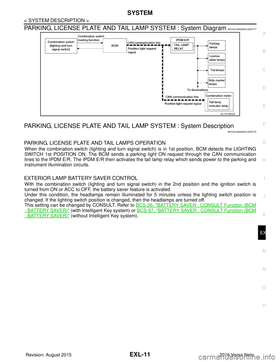
PARKING, LICENSE PLATE AND TAIL LAMP SYSTEM : System DiagramINFOID:0000000012432777
PARKING, LICENSE PLATE AND TAIL LA MP SYSTEM : System Description
INFOID:0000000012432778
PARKING, LICENSE PLATE AND TAIL LAMPS OPERATION
When the combination switch (lighting and turn signal s witch) is in 1st position, BCM detects the LIGHTING
SWITCH 1st POSITION ON. The BCM sends a parking light ON request through the CAN communication
lines to the IPDM E/R. The IPDM E/R then activates the tail lamp relay which sends power to the parking and
instrument illumination circuits.
EXTERIOR LAMP BATTERY SAVER CONTROL
With the combination switch (lighting and turn signal switch) in the 2nd position and the ignition switch is
turned from ON or ACC to OFF, the battery saver feature is activated.
Under this condition, the headlamps remain illuminated for 5 minutes unless the lighting switch position is
changed. If the lighting switch position is changed, then the headlamps are turned off.
This setting can be changed by CONSULT. Refer to BCS-26, "
BATTERY SAVER : CONSULT Function (BCM
- BATTERY SAVER)" (with Intelligent Key system) or BCS-97, "BATTERY SAVER : CONSULT Function (BCM
- BATTERY SAVER)" (without Intelligent Key system).
ALLIA1562GB
Revision: August 2015 2016 Versa Note
cardiagn.com
Page 1665 of 3641

DIAGNOSIS SYSTEM (BCM) (WITH INTELLIGENT KEY SYSTEM)
EXL-13
< SYSTEM DESCRIPTION >
C
D E
F
G H
I
J
K
M A
B
EXL
N
O P
HEADLAMP
HEADLAMP : CONSULT Function (BCM - HEAD LAMP)INFOID:0000000012542303
DATA MONITOR
ACTIVE TEST
WORK SUPPORT
*: Initial setting
FLASHER
Monitor Item [Unit] Description
PUSH SW [On/Off] Indicates condition of push-button ignition switch.
ENGINE STATE [Stop/Stall/Crank/Run] Indicates engine status received from ECM on CAN communication line.
VEH SPEED 1 [km/h] Indicates vehicle speed signal received from ABS on CAN communication line.
TURN SIGNAL R [On/Off]
Indicates condition of combination switch.
TURN SIGNAL L [On/Off]
TAIL LAMP SW [On/Off]
HI BEAM SW [On/Off]
HEAD LAMP SW 1 [On/Off]
HEAD LAMP SW 2 [On/Off]
PASSING SW [On/Off]
FR FOG SW [On/Off]
DOOR SW-DR [On/Off]
Indicates condition of front door switch LH.
DOOR SW-AS [On/Off] Indicates condition of front door switch RH.
DOOR SW-RR [On/Off] Indicates condition of rear door switch RH.
DOOR SW-RL [On/Off] Indicates condition of rear door switch LH.
DOOR SW-BK [On/Off] Indicates condition of back door switch.
Test Item Description
FR FOG LAMP This test is able to check front fog lamp operation [On/Off].
HEAD LAMP This test is able to check head lamp operation [Hi/Low/Off].
ILL DIM SIGNAL This test is able to check head lamp illumination dimming operation [On/Off].
TAIL LAMP This test is able to check tail lamp operation [On/Off].
Support ItemSetting Description
BATTERY SAVER SET On*
Exterior lamp battery saver function ON.
Off Exterior lamp battery saver function OFF.
ILL DELAY SET MODE 8 180 sec.
Sets delay timer function operation time
(All doors closed).
MODE 7 150 sec.
MODE 6 120 sec.
MODE 4 60 sec.
MODE 5 90 sec.
MODE 3 30 sec.
MODE 2 OFF
MODE 1* 45 sec.
Revision: August 2015
2016 Versa Note
cardiagn.com
Page 1669 of 3641

DIAGNOSIS SYSTEM (BCM) (WITHOUT INTELLIGENT KEY SYSTEM)EXL-17
< SYSTEM DESCRIPTION >
C
DE
F
G H
I
J
K
M A
B
EXL
N
O P
HEADLAMP
HEADLAMP : CONSULT Function (BCM - HEAD LAMP)INFOID:0000000012542312
DATA MONITOR
ACTIVE TEST
WORK SUPPORT
* : Initial setting
FLASHER
FLASHER : CONSULT Func tion (BCM - FLASHER)INFOID:0000000012542313
DATA MONITOR
Monitor Item [Unit] Description
IGN ON SW [On/Off] Indicates condition of ignition switch ON position.
ACC ON SW [On/Off] Indicates condition of ignition switch ACC position.
HI BEAM SW [On/Off]
Indicates condition of combination switch.
HEAD LAMP SW 1 [On/Off]
HEAD LAMP SW 2 [On/Off]
TAIL LAMP SW [On/Off]
PASSING SW [On/Off]
FR FOG SW [On/Off]
DOOR SW-DR [On/Off]
Indicates condition of front door switch LH.
DOOR SW-AS [On/Off] Indicates condition of front door switch RH.
DOOR SW-RR [On/Off] Indicates condition of rear door switch RH.
DOOR SW-RL [On/Off] Indicates condition of rear door switch LH.
DOOR SW-BK [On/Off] Indicates condition of back door switch.
TURN SIGNAL R [On/Off] Indicates condition of combination switch.
TURN SIGNAL L [On/Off]
KEY ON SW [On/Off] Indicates condition of key switch.
KEYLESS LOCK [On/Off] Indicates condition of lock signal from keyfob.
PKB SW [On/Off] Indicates park brake switch signal received from combination meter on CAN communica-
tion line.
ENGINE RUN [On/Off] Indicates engine run signal receiv ed from ECM on CAN communication line.
VEHICLE SPEED [km/h/mph] Indicates vehicle speed signal received from combination meter on CAN communication
line.
Test Item
Description
TAIL LAMP This test is able to check tail lamp operation [On/Off].
HEAD LAMP This test is able to check head lamp operation [Hi/Low/Off].
FR FOG LAMP This test is able to check front fog lamp operation [On/Off].
ILL DIM SIGNAL This test is able to check head lamp illumination dimming operation [On/Off].
Support ItemSetting Description
BATTERY SAVER SET On*
Exterior lamp battery saver function ON.
Off Exterior lamp battery saver function OFF.
Revision: August 2015 2016 Versa Note
cardiagn.com
Page 1672 of 3641

EXL-20
< SYSTEM DESCRIPTION >
DIAGNOSIS SYSTEM (IPDM E/R)
DIAGNOSIS SYSTEM (IPDM E/R)
Diagnosis DescriptionINFOID:0000000012542316
AUTO ACTIVE TEST
Description
In auto active test, the IPDM E/R sends a drive signal to the following systems to check their operation:
• Front wiper (LO, HI)
• Parking lamp
• Side marker lamp
• License plate lamp
• Tail lamp
• Front fog lamp
• Headlamp (LO, HI)
• A/C compressor (magnet clutch)
• Cooling fan
Operation Procedure
NOTE:
Never perform auto active test in the following conditions:
• Passenger door is open
• CONSULT is connected
1. Close the hood and lift the wiper arms from the windshield. (Prevent windshield damage due to wiper
operation)
NOTE:
When auto active test is performed with hood opened, sprinkle water on windshield beforehand.
2. Turn the ignition switch OFF.
3. Turn the ignition switch ON, and within 20 seconds, pr ess the driver door switch 10 times. Then turn the
ignition switch OFF.
4. Turn the ignition switch ON within 10 seconds. Af ter that the horn sounds once and the auto active test
starts.
5. After a series of the following operations is repeated 3 times, auto active test is completed.
NOTE:
• When auto active test has to be cancelled halfw ay through test, turn the ignition switch OFF.
• When auto active test is not activated, door swit ch may be the cause. Check door switch. Refer to DLK-98,
"ComponentFunctionCheck" (with Intelligent Key system) or DLK-232, "ComponentFunctionCheck"
(without Intelligent Key system).
Inspection in Auto Active Test
When auto active test is actuated, the following operation sequence is repeated 3 times.
Operation se-
quence Inspection location
Operation
1 Front wiper LO for 5 seconds → HI for 5 seconds
2 •Parking lamp
• Side marker lamp
• License plate lamp
• Tail lamp
• Front fog lamp (if equipped) 10 seconds
3 Headlamp LO for 10 seconds →HI ON ⇔ OFF 5 times
4 A/C compressor (magnet clutch) ON ⇔ OFF 5 times
5 Cooling fan LO for 5 seconds → MID for 3 seconds → HI for 2 seconds
Revision: August 2015 2016 Versa Note
cardiagn.com
Page 1673 of 3641
DIAGNOSIS SYSTEM (IPDM E/R)EXL-21
< SYSTEM DESCRIPTION >
C
DE
F
G H
I
J
K
M A
B
EXL
N
O P
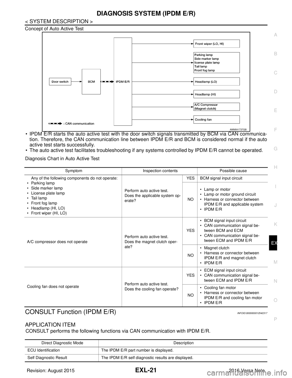
Concept of Auto Active Test
• IPDM E/R starts the auto active test with the door
switch signals transmitted by BCM via CAN communica-
tion. Therefore, the CAN communication line between IPDM E/R and BCM is considered normal if the auto
active test starts successfully.
• The auto active test facilitates troubleshooting if any systems controlled by IPDM E/R cannot be operated.
Diagnosis Chart in Auto Active Test
CONSULT Function (IPDM E/R)INFOID:0000000012542317
APPLICATION ITEM
CONSULT performs the following functions via CAN communication with IPDM E/R.
AWMIA1737GB
SymptomInspection contentsPossible cause
Any of the following components do not operate:
•Parking lamp
• Side marker lamp
• License plate lamp
•Tail lamp
•Front fog lamp
• Headlamp (HI, LO)
• Front wiper (HI, LO) Perform auto active test.
Does the applicable system op-
erate?YES BCM signal input circuit
NO • Lamp or motor
• Lamp or motor ground circuit
• Harness or connector between
IPDM E/R and applicable system
•IPDM E/R
A/C compressor does not operate Perform auto active test.
Does the magnet clutch oper-
ate?YES
• BCM signal input circuit
• CAN communication signal be-
tween BCM and ECM
• CAN communication signal be-
tween ECM and IPDM E/R
NO • Magnet clutch
• Harness or connector between
IPDM E/R and magnet clutch
•IPDM E/R
Cooling fan does not operate Perform auto active test.
Does the cooling fan operate?YES
• ECM signal input circuit
• CAN communication signal be-
tween ECM and IPDM E/R
NO • Cooling fan motor
• Harness or connector between
IPDM E/R and cooling fan motor
•IPDM E/R
Direct Diagnostic Mode Description
ECU Identification The IPDM E/R part number is displayed.
Self Diagnostic Result The IPDM E/R self diagnostic results are displayed.
Revision: August 2015 2016 Versa Note
cardiagn.com