Page 1527 of 3641
![NISSAN NOTE 2016 Service Repair Manual EC-400
< DTC/CIRCUIT DIAGNOSIS >[HR16DE]
P2096, P2097 A/F SENSOR 1
4. Check the continuity between ECM harness connec
tor or A/F sensor 1 harness connector and ground.
5. Also check harness for short NISSAN NOTE 2016 Service Repair Manual EC-400
< DTC/CIRCUIT DIAGNOSIS >[HR16DE]
P2096, P2097 A/F SENSOR 1
4. Check the continuity between ECM harness connec
tor or A/F sensor 1 harness connector and ground.
5. Also check harness for short](/manual-img/5/57363/w960_57363-1526.png)
EC-400
< DTC/CIRCUIT DIAGNOSIS >[HR16DE]
P2096, P2097 A/F SENSOR 1
4. Check the continuity between ECM harness connec
tor or A/F sensor 1 harness connector and ground.
5. Also check harness for short to power.
Is the inspection result normal?
YES >> GO TO 10.
NO >> Repair open circuit or short to ground or short to power in harness or connectors.
10.CHECK A/F SENSOR 1 HEATER
Refer to EC-175, "
Component Inspection".
Is the inspection result normal?
YES >> GO TO 11.
NO >> GO TO 13.
11 .CHECK HEATED OXYGEN SENSOR 2
Refer to EC-226, "
Component Inspection".
Is the inspection result normal?
YES >> GO TO 12.
NO >> Replace heated oxygen sensor 2. Refer to EX-5, "
Exploded View".
12.CHECK INTERMITTENT INCIDENT
Perform GI-42, "
Intermittent Incident".
Is the inspection result normal?
YES >> GO TO 13.
NO >> Repair or replace.
13.REPLACE AIR FUEL RATIO (A/F) SENSOR 1
Replace air fuel ratio (A/F) sensor 1. Refer to EM-31, "
Removal and Installation".
CAUTION:
• Discard any sensor which has been dropped from a height of more than 0.5 m (19.7 in) onto a hard
surface such as a concrete floor; use a new one.
• Before installing new sensor, cl ean exhaust system threads using oxygen sensor thread cleaner tool
[commercial service tool: (J-43897-18) or (J-43897-12)] and approved anti-seize lubricant (commer-
cial service tool).
Do you have CONSULT?
YES >> GO TO 14.
NO >> GO TO 15.
14.CONFIRM A/F ADJUSTMENT DATA
With CONSULT
1. Turn ignition switch ON.
2. Select “A/F ADJ-B1” in “D ATA MONITOR” mode with CONSULT.
3. Make sure that “0.000” is displayed on CONSULT screen.
Is
“0.000” displayed?
YES >> INSPECTION END
NO >> GO TO 15.
A/F sensor 1 ECM
Continuity
Connector Terminal Connector Terminal
F12 1
F11 49
Existed
25 3
A/F sensor 1 ECM
Ground Continuity
Connector Terminal Connector Terminal
F12 1
F11 49
Ground Not existed
25 3
Revision: August 2015 2016 Versa Note
cardiagn.com
Page 1651 of 3641

EX-6
< REMOVAL AND INSTALLATION >
EXHAUST SYSTEM
INSTALLATION
Installation is in the reverse order of removal.
CAUTION:
• Do not reuse gasket.
• Do not reuse seal bearing.
• Discard any heated oxygen sensor 2 which has been dropped from a height of more than 0.5 m (19.7
in) onto a hard surface such as a concrete floor. Use a new one.
• Before installing a new heated o xygen sensor 2, clean exhaust system threads using a suitable tool
and apply anti-seize lubricant.
• Do not over tighten heated oxygen sensor 2. Doin g so may cause damage to the heated oxygen sen-
sor 2, resulting in the “MIL” coming on.
• Prevent rust preventives from adhering to the sensor body.
• If heat insulator is badly deformed, repair or re place it. If deposits such as mud pile up on the heat
insulator, remove them.
• When installing heat insulator avoid large gaps or interference between heat insulator and each
exhaust pipe.
• Remove deposits from the sealing surface of each connection. Connect them securely to avoid
exhaust gas leaks.
• When installing each mounting rubber, use silicon oil to avoid twisting.
• Temporarily tighten nuts and bolts. Check each part for unusual interference and mounting rubber interference, and then tighten them to the specified torque.
• When installing each mounting rubber, avoid twisting or unus ual extension in up/down, front/rear
and right/left directions.
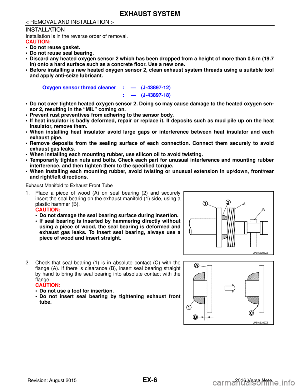
Exhaust Manifold to Exhaust Front Tube
1. Place a piece of wood (A) on seal bearing (2) and securely insert the seal bearing on the exhaust manifold (1) side, using a
plastic hammer (B).
CAUTION:
• Do not damage the seal bearing surface during insertion.
• If seal bearing is inserted by hammering directly without
using a piece of wood, the seal bearing is deformed and
exhaust gas leaks. To insert seal bearing, always use a
piece of wood and insert straight.
2. Check that seal bearing (1) is in absolute contact (C) with the flange (A). If there is clearance (B), insert seal bearing straight
by hand to bring the seal bearing into absolute contact with the
flange.
CAUTION:
• Do not use a tool for insertion.
• Do not insert seal bearing by tightening exhaust front
tube. Oxygen sensor thread cleaner : — (J-43897-12)
: — (J-43897-18)
JPBIA6288ZZ
JPBIA6289ZZ
Revision: August 2015 2016 Versa Note
cardiagn.com
Page 1751 of 3641
HEADLAMP AIMING ADJUSTMENTEXL-99
< PERIODIC MAINTENANCE >
C
DE
F
G H
I
J
K
M A
B
EXL
N
O P
7. Measure the projected beam within t he aim evaluation segment on the screen.
8. Adjust the beam pattern of each headlamp until the ai m evaluation segment (the area relative to both the
highest and lowest cutoff line height) is positioned within the vertical aim range dimensions shown on the
aiming chart.
Revision: August 2015 2016 Versa Note
cardiagn.com
Page 1753 of 3641
FRONT FOG LAMP AIMING ADJUSTMENTEXL-101
< PERIODIC MAINTENANCE >
C
DE
F
G H
I
J
K
M A
B
EXL
N
O P
3. Adjust the cutoff line height (A) with the aiming adjustment screw so that the distance (X) between the horizontal center line
of front fog lamp (H) and (A) becomes 200 mm (7.87 in).
Front fog lamp light distribution on the screen
• A :Cutoff line
• B :High illuminance
• H :Horizontal center line of front fog lamp
• V :Vertical center line of front fog lamp
• X :Cutoff line height
JPLIA0008ZZ
Revision: August 2015 2016 Versa Note
cardiagn.com
Page 1793 of 3641
EXT-26
< REMOVAL AND INSTALLATION >
FRONT BUMPER
TYPE 1
AWKIA2515ZZ
SectionMeasurement MinimumTarget Value Maximum
A-A Clearance 0.0 (0.00)2.0 (0.08)4.0 (0.16)
B-B Clearance 2.4 (0.09)4.4 (0.17)6.4 (0.25)
B-B Surface height -1.5 (-0.06)0.5 (0.02)1.99 (0.08)
C-C Clearance 0.0 (0.00)2.0 (0.08)4.0 (0.16)
D-D Clearance 0.0 (0.00)1.5 (0.06)3.0 (0.12)
D-D Surface height 0.0 (0.00)1.5 (0.06)3.0 (0.12)
E-E Clearance 0.01 (0.00)2.0 (0.08)4.0 (0.16)
F-F Clearance 0.1 (0.00)0.3 (0.01)1.0 (0.04)
F-F Surface height -0.1 (0.00)0.7 (0.03)1.7 (0.07)
Revision: August 2015 2016 Versa Note
cardiagn.com
Page 1794 of 3641
FRONT BUMPEREXT-27
< REMOVAL AND INSTALLATION >
C
DE
F
G H
I
J
L
M A
B
EXT
N
O P
TYPE 2
ALKIA3632ZZ
Section Measurement MinimumTarget Value Maximum
A-A Clearance -1.8 (-0.07)0.7 (0.03)3.2 (0.13)
B-B Clearance 2.4 (0.09)4.4 (0.17)6.4 (0.25)
B-B Surface height -1.5 (-0.06)0.5 (0.02)1.99 (0.08)
C-C Clearance 0.0 (0.00)2.0 (0.08)4.0 (0.16)
D-D Clearance 0.0 (0.00)1.5 (0.06)3.0 (0.12)
D-D Surface height 0.0 (0.00)1.5 (0.06)3.0 (0.12)
E-E Clearance 0.01 (0.00)2.0 (0.08)4.0 (0.16)
F-F Clearance 0.1 (0.00)0.3 (0.01)1.0 (0.04)
F-F Surface height -0.1 (0.00)0.7 (0.03)1.7 (0.07)
Revision: August 2015 2016 Versa Note
cardiagn.com
Page 1798 of 3641
REAR BUMPEREXT-31
< REMOVAL AND INSTALLATION >
C
DE
F
G H
I
J
L
M A
B
EXT
N
O P
TYPE 1
TYPE 2
ALKIA3207ZZ
Section Measurement MinimumTarget Value Maximum
A-A Clearance 0.1 (0.00)0.3 (0.01)1.0 (0.04)
B-B Clearance 0.0 (0.00)1.5 (0.06)3.5 (0.14)
B-B Surface height -1.5 (-0.06)0.5 (0.02)2.5 (0.10)
C-C Clearance 3.0 (0.12)5.0 (0.20)7.0 (0.28)
C-C Surface height -2.0 (-0.08) -1.5 (-0.06) 0.5 (0.02)
D-D Clearance 5.0 (0.20)7.0 (0.28)9.0 (0.35)
ALKIA3633ZZ
SectionMeasurement MinimumTarget Value Maximum
A-A Clearance 5.0 (0.20)7.0 (0.28)9.0 (0.35)
B-B Clearance 3.0 (0.12)5.0 (0.20)7.0 (0.28)
B-B Surface height -2.0 (-0.08) -1.5 (-0.06) 0.5 (0.02)
C-C Clearance 0.0 (0.00)1.5 (0.06)3.5 (0.14)
C-C Surface height -1.5 (-0.06)0.5 (0.02)2.5 (0.10)
D-D Clearance -1.5 (-0.06)-0.7 (0.03) 0.3 (0.01)
Revision: August 2015 2016 Versa Note
cardiagn.com
Page 1846 of 3641

FSU-1
SUSPENSION
C
DF
G H
I
J
K L
M
SECTION FSU
A
B
FSU
N
O PCONTENTS
FRONT SUSPENSION
PRECAUTION ....... ........................................2
PRECAUTIONS .............................................. .....2
Precaution for Supplemental Restraint System
(SRS) "AIR BAG" and "SEAT BELT PRE-TEN-
SIONER" ............................................................. ......
2
Precaution for Procedure without Cowl Top Cover ......2
Precaution for Suspension ........................................2
PREPARATION ............................................3
PREPARATION .............................................. .....3
Special Service Tools .......................................... ......3
Commercial Service Tools ........................................3
SYMPTOM DIAGNOSIS ...............................5
NOISE, VIBRATION AND HARSHNESS
(NVH) TROUBLESHOOTING ........................ .....
5
NVH Troubleshooting Chart ................................ ......5
PERIODIC MAINTENANCE ..........................6
FRONT SUSPENSION ASSEMBLY .............. .....6
Inspection ............................................................ ......6
WHEEL ALIGNMENT ..........................................7
Inspection ............................................................ ......7
Adjustment ................................................................8
REMOVAL AND INSTALLATION ................9
FRONT COIL SPRING AND STRUT ............. .....9
Exploded View .................................................... ......9
Removal and Installation ...........................................9
TRANSVERSE LINK .........................................10
Exploded View ..................................................... ....10
Removal and Installation .........................................10
Inspection ................................................................10
FRONT STABILIZER ........................................12
Exploded View .........................................................12
Removal and Installation .........................................12
Inspection ................................................................13
UNIT REMOVAL AND INSTALLATION ......14
FRONT SUSPENSION MEMBER .....................14
Exploded View ..................................................... ....14
Removal and Installation .........................................14
Inspection ................................................................15
UNIT DISASSEMBLY AND ASSEMBLY ....16
FRONT COIL SPRING AND STRUT ................16
Exploded View ..................................................... ....16
Disassembly and Assembly .....................................16
Inspection ................................................................19
Disposal ...................................................................19
SERVICE DATA AND SPECIFICATIONS
(SDS) ............... .......................................... ...
20
SERVICE DATA AND SPECIFICATIONS
(SDS) .................................................................
20
Wheel Alignment (Unladen*1) ..................................20
Ball Joint .............................................................. ....20
Wheelarch Height (Unladen*) ..................................21
Revision: August 2015 2016 Versa Note
cardiagn.com