2016 NISSAN NOTE warning
[x] Cancel search: warningPage 2776 of 3641
LOW TIRE PRESSURE WARNING LAMPWT-33
< DTC/CIRCUIT DIAGNOSIS >
C
DF
G H
I
J
K L
M A
B
WT
N
O P
LOW TIRE PRESSUR E WARNING LAMP
Component Function CheckINFOID:0000000012432453
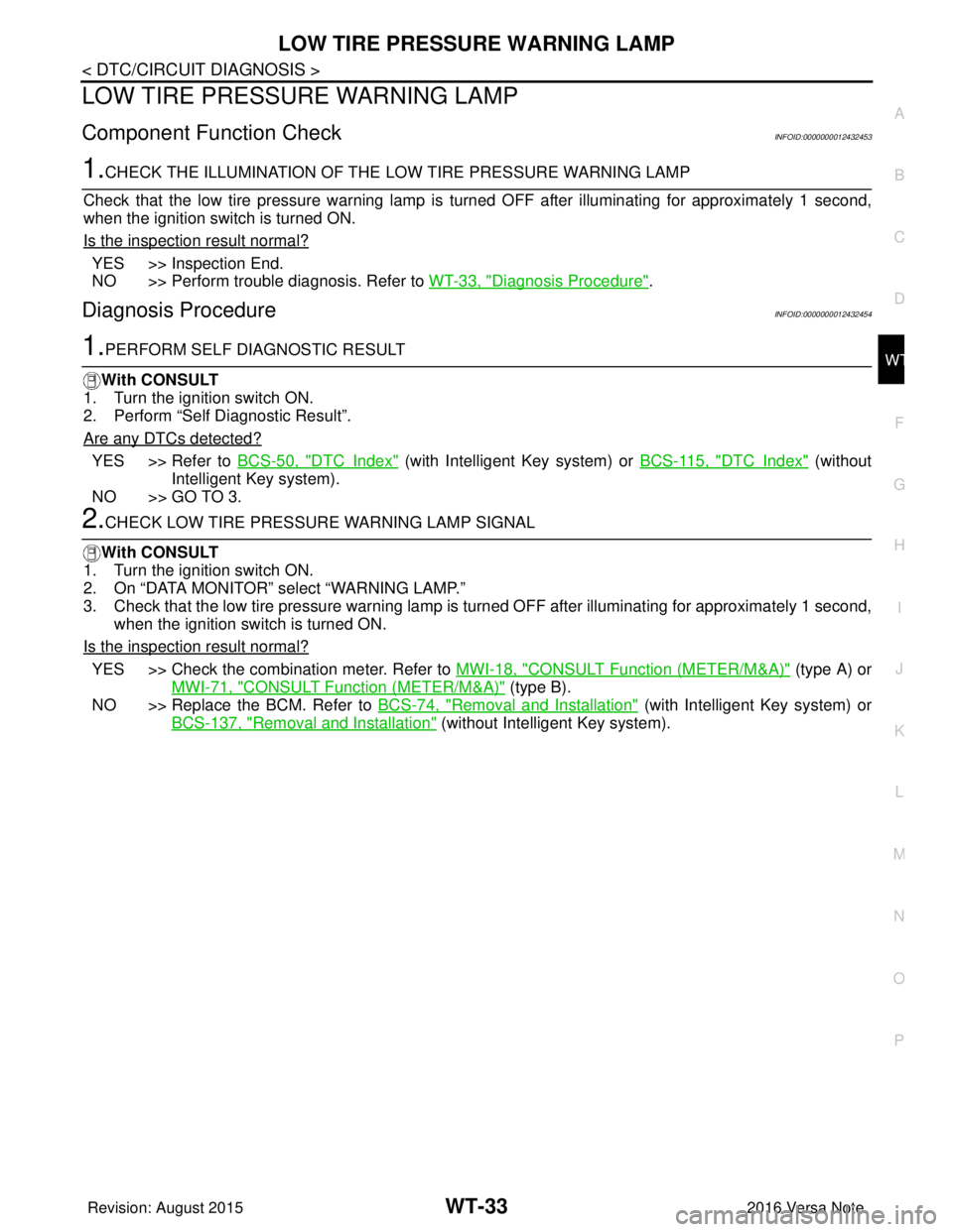
1.CHECK THE ILLUMINATION OF THE LOW TIRE PRESSURE WARNING LAMP
Check that the low tire pressure warning lamp is turned OFF after illuminating for approximately 1 second,
when the ignition switch is turned ON.
Is the inspection result normal?
YES >> Inspection End.
NO >> Perform trouble diagnosis. Refer to WT-33, "
Diagnosis Procedure".
Diagnosis ProcedureINFOID:0000000012432454
1.PERFORM SELF DIAGNOSTIC RESULT
With CONSULT
1. Turn the ignition switch ON.
2. Perform “Self Diagnostic Result”.
Are any DTCs detected?
YES >> Refer to BCS-50, "DTCIndex" (with Intelligent Key system) or BCS-115, "DTCIndex" (without
Intelligent Key system).
NO >> GO TO 3.
2.CHECK LOW TIRE PRESSURE WARNING LAMP SIGNAL
With CONSULT
1. Turn the ignition switch ON.
2. On “DATA MONITOR” select “WARNING LAMP.”
3. Check that the low tire pressure warning lamp is turned OFF after illuminating for approximately 1 second,
when the ignition switch is turned ON.
Is the inspection result normal?
YES >> Check the combination meter. Refer to MWI-18, "CONSULT Function (METER/M&A)" (type A) or
MWI-71, "
CONSULT Function (METER/M&A)" (type B).
NO >> Replace the BCM. Refer to BCS-74, "
Removal and Installation" (with Intelligent Key system) or
BCS-137, "
Removal and Installation" (without Intelligent Key system).
Revision: August 2015 2016 Versa Note
cardiagn.com
Page 2779 of 3641

WT-36
< SYMPTOM DIAGNOSIS >
TPMS SYMPTOMS
SYMPTOM DIAGNOSIS
TPMS SYMPTOMS
Symptom TableINFOID:0000000012432457
SymptomReference
Low tire pressure warning lamp does not turn ON. WT-37
Low tire pressure warning lamp does not turn OFF.WT-38
Low tire pressure warning lamp blinks. WT-39
ID registration cannot be completed. WT-42
Easy fill alert does not activate.WT-40
Revision: August 20152016 Versa Note
cardiagn.com
Page 2780 of 3641
LOW TIRE PRESSURE WARNING LAMP DOES NOT TURN ON
WT-37
< SYMPTOM DIAGNOSIS >
C
D F
G H
I
J
K L
M A
B
WT
N
O P
LOW TIRE PRESSURE WARNIN G LAMP DOES NOT TURN ON
Diagnosis ProcedureINFOID:0000000012432458
NOTE:
The Signal Tech II Tool [- (J-50190)] can be used to perform the following functions. Refer to the Signal Tech II
User Guide for additional information.
• Activate and display TPMS transmitter IDs
• Display tire pressure reported by the TPMS transmitter
• Read TPMS DTCs
• Register TPMS transmitter IDs
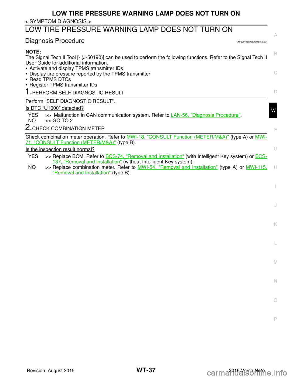
1.PERFORM SELF DIAGNOSTIC RESULT
Perform “SELF DIAGNOSTIC RESULT”.
Is DTC
“U1000” detected?
YES >> Malfunction in CAN communication system. Refer to LAN-56, "Diagnosis Procedure".
NO >> GO TO 2
2.CHECK COMBINATION METER
Check combination meter operation. Refer to MWI-18, "
CONSULT Function (METER/M&A)" (type A) or MWI-
71, "CONSULT Function (METER/M&A)" (type B).
Is the inspection result normal?
YES >> Replace BCM. Refer to BCS-74, "Removal and Installation" (with Intelligent Key system) or BCS-
137, "Removal and Installation" (without Intelligent Key system).
NO >> Replace combination meter. Refer to MWI-54, "
Removal and Installation" (type A) or MWI-115,
"Removal and Installation" (type B).
Revision: August 2015 2016 Versa Note
cardiagn.com
Page 2781 of 3641
WT-38
< SYMPTOM DIAGNOSIS >
LOW TIRE PRESSURE WARNING LAMP DOES NOT TURN OFF
LOW TIRE PRESSURE WARNING LAMP DOES NOT TURN OFF
Diagnosis ProcedureINFOID:0000000012432459
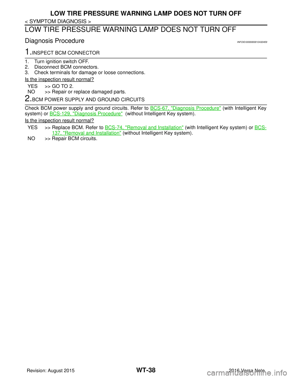
1.INSPECT BCM CONNECTOR
1. Turn ignition switch OFF.
2. Disconnect BCM connectors.
3. Check terminals for damage or loose connections.
Is the inspection result normal?
YES >> GO TO 2.
NO >> Repair or replace damaged parts.
2.BCM POWER SUPPLY AND GROUND CIRCUITS
Check BCM power supply and ground circuits. Refer to BCS-67, "
Diagnosis Procedure" (with Intelligent Key
system) or BCS-129, "
Diagnosis Procedure" (without Intelligent Key system).
Is the inspection result normal?
YES >> Replace BCM. Refer to BCS-74, "Removal and Installation" (with Intelligent Key system) or BCS-
137, "Removal and Installation" (without Intelligent Key system).
NO >> Repair BCM circuits.
Revision: August 2015 2016 Versa Note
cardiagn.com
Page 2782 of 3641
LOW TIRE PRESSURE WARNING LAMP BLINKSWT-39
< SYMPTOM DIAGNOSIS >
C
DF
G H
I
J
K L
M A
B
WT
N
O P
LOW TIRE PRESSURE WA RNING LAMP BLINKS
Diagnosis ProcedureINFOID:0000000012432460
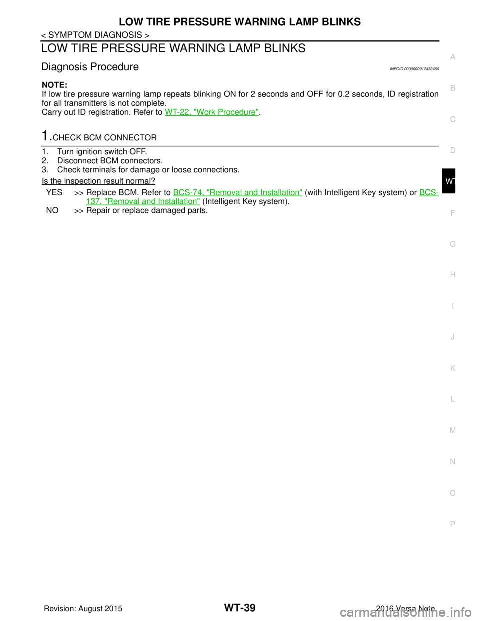
NOTE:
If low tire pressure warning lamp repeats blinking ON for 2 seconds and OFF for 0.2 seconds, ID registration
for all transmitters is not complete.
Carry out ID registration. Refer to WT-22, "
Work Procedure".
1.CHECK BCM CONNECTOR
1. Turn ignition switch OFF.
2. Disconnect BCM connectors.
3. Check terminals for damage or loose connections.
Is the inspection result normal?
YES >> Replace BCM. Refer to BCS-74, "Removal and Installation" (with Intelligent Key system) or BCS-
137, "Removal and Installation" (Intelligent Key system).
NO >> Repair or replace damaged parts.
Revision: August 2015 2016 Versa Note
cardiagn.com
Page 2783 of 3641
WT-40
< SYMPTOM DIAGNOSIS >
EASY FILL TIRE ALERT DOES NOT ACTIVATE
EASY FILL TIRE ALERT DOES NOT ACTIVATE
DescriptionINFOID:0000000012432461
The easy fill tire alert does not function while inflating a tire when the select lever position is in P-range with the
ignition switch ON.
NOTE:
• After starting to inflate the tire, it takes a few seconds for the easy fill tire alert to function.
• If there is no response for approximately 15 seconds or mo re after inflating the tires, cancel the use of the
easy fill tire alert function or move the vehicle approximately 1 m (3.2 ft) backward or forward to try again.
The air filler pressure may be weak or out of service area.
• For easy fill tire alert, Refer to WT-8, "
TIRE PRESSURE MONITORING SYST EM : Easy Fill Tire Alert Func-
tion".
Diagnosis ProcedureINFOID:0000000012432462
1. LOCATION CHANGE
Move the vehicle to other area and repeat the procedure of the easy fill tire alert function. Refer to WT-8,
"TIRE PRESSURE MONITORING SYSTEM : Easy Fill Tire Alert Function".
Is the function normal?
YES >> Normal (the easy fill tire alert may not operate, depending on reception condition.)
NO >> GO TO 2.
2.PERFORM BCM SELF-DIAGNOSIS
With CONSULT
Perform self-diagnosis for “AIR PRESSURE MONITOR”.
Is any DTC detected?
YES >> Perform trouble diagnosis for detected DTC. Refer to BCS-50, "DTCIndex" (with Intelligent Key
system) or BCS-115, "
DTCIndex" (without Intelligent Key system).
NO >> GO TO 3.
3.CHECK HAZARD WARNING LAMP OPERATION
Check hazard warning lamp operation with hazard switch.
Does the hazard warning lamp blink?
YES >> GO TO 4.
NO >> Perform trouble diagnosis for the hazard warning lamp. Refer to EXL-85, "
Diagnosis Procedure" .
4.PERFORM TCM SELF-DIAGNOSIS
With CONSULT
Perform self-diagnosis for “TRANSMISSION”.
Is any DTC detected?
YES >> Check malfunctioning circuit. Refer to TM-110, "DTC Index".
NO >> GO TO 5.
5.CHECK HORN OPERATION
Check horn operation. Refer to HRN-3, "
Wiring Diagram".
Is the operation normal?
YES >> GO TO 6.
NO >> Repair or replace error-detected parts.
6.PERFORM BCM SELF-DIAGNOSIS
With CONSULT
1. Drive for 10 minutes at a speed of 40 km/h (25 MPH) or more.
CAUTION:
Total time driving at a speed of 40 km/h (25 MPH) or more must be 10 minutes.
2. Stop the vehicle.
3. Perform self-diagnosis for “AIR PRESSURE MONITOR”.
Revision: August 2015 2016 Versa Note
cardiagn.com
Page 2789 of 3641
WT-46
< PERIODIC MAINTENANCE >
WHEEL AND TIRE
3. Install balance weight in the position shown.CAUTION:
• Do not install the inner bala nce weight before installing
the outer balance weight.
• Before installing the balance weight, be sure to clean the mating surface of the wheel and tire.
• When installing balance weight (1) to wheel and tire, set it into the grooved area (A) on the inner wall of the wheel and tire as
shown so that the balance weight center (B) is aligned with the
balancer machine indication position (angle) (C).
CAUTION:
• Always use Genuine NISSAN adhesive balance weights.
• Balance weights are non-reusable; always replace withnew ones.
• Do not install more than three sheets of balance weights.
4. If calculated balance weight value exceeds 50 g (1.76 oz), install two balance weight sheets in line with each other as shown.
CAUTION:
Do not install one balance weight sheet on top of another.
5. Start balancer machine again.
6. Install balance weight on inner side of wheel and tire in the bal- ancer machine indication position (angle).
CAUTION:
Do not install more than two balance weights.
7. Start balancer machine. Make sure that inner and outer residual imbalance values are 5 g (0.17 oz) each or below.
8. If either residual imbalance value exceeds 5 g (0.17 oz), repeat installation procedures.
TIRE ROTATION
• Follow the maintenance schedule for tire rotation service intervals.
Refer to MA-7, "
Introduction of Periodic Maintenance".
• Rotate the wheel and tires front to back in the pattern as shown.
• When installing the wheel, tighten wheel nuts to the specified torque.
WARNING:
• After rotating the tires, check and adjust the tire pressure.
• Do not include the spare tire when rotating the tires.
CAUTION:
• When installing wheels, tighten them diagonally by dividing
the work two to three times in order to prevent the wheels
from developing any distortion.
• Be careful not to tighten the wh eel nuts to a torque exceeding speci fication to prevent strain on the
disc rotor.
• Use Genuine NISSAN wheel nuts.
JPEIC0040ZZ
Wheel balance Dynamic (At flange) Static (At flange)
Maximum allowable im-
balance Refer to WT-54, "
Wheel".
PEIA0033E
SMA829C
Revision: August 2015
2016 Versa Note
cardiagn.com
Page 2799 of 3641

SB-2
< PRECAUTION >
PRECAUTIONS
PRECAUTION
PRECAUTIONS
Precaution for Supplemental Restraint System (SRS) "AIR BAG" and "SEAT BELT
PRE-TENSIONER"
INFOID:0000000012430695
The Supplemental Restraint System such as “A IR BAG” and “SEAT BELT PRE-TENSIONER”, used along
with a front seat belt, helps to reduce the risk or severity of injury to the driver and front passenger for certain
types of collision. Information necessary to service the system safely is included in the SR and SB section of
this Service Manual.
WARNING:
• To avoid rendering the SRS inopera tive, which could increase the risk of personal injury or death in
the event of a collision which would result in air bag inflation, all maintenance must be performed by
an authorized NISSAN/INFINITI dealer.
• Improper maintenance, including in correct removal and installation of the SRS, can lead to personal
injury caused by unintent ional activation of the system. For re moval of Spiral Cable and Air Bag
Module, see the SR section.
• Do not use electrical test equipmen t on any circuit related to the SRS unless instructed to in this
Service Manual. SRS wiring harn esses can be identified by yellow and/or orange harnesses or har-
ness connectors.
PRECAUTIONS WHEN USING POWER TOOLS (AIR OR ELECTRIC) AND HAMMERS
WARNING:
• When working near the Airbag Diagnosis Sensor Unit or other Airbag System sensors with the Igni-
tion ON or engine running, DO NOT use air or electri c power tools or strike near the sensor(s) with a
hammer. Heavy vibration could activate the sensor( s) and deploy the air bag(s), possibly causing
serious injury.
• When using air or electric power tools or hammers , always switch the Ignition OFF, disconnect the
battery and wait at least three minutes before performing any service.
Precaution for Seat Belt ServiceINFOID:0000000012430696
CAUTION:
• Before removing the seat belt pre-tensioner assembl y, turn the ignition switch OFF, disconnect both
battery terminals and wait at least three minutes. For approximately three minutes after the battery
terminals have been removed, it is still possible for the air bag and seat belt pre-tensioner to deploy.
Therefore, do not attempt work on any SRS connectors or wires until at least three minutes have
passed.
• After replacing or reinstalling seat belt pre -tensioner assembly or reconnecting seat belt pre-ten-
sioner assembly connector, make sure entire SRS operates properly. Refer to SRC-14, "
Description".
• Do not disassemble buckle or seat belt assembly.
• Replace anchor bolts if th ey are deformed or worn out.
• Do not oil tongue or buckle.
• If any component of seat belt assembly is questionable, do not re pair. Replace the whole seat belt
assembly.
• If webbing is cut, frayed or damaged, replace seat belt assembly.
• When replacing seat belt assembly, use a genuine NISSAN seat belt assembly.
Precaution for WorkINFOID:0000000012430697
• When removing or disassembling each component, be careful not to damage or deform it. If a component may be subject to interference, be sure to protect it with a shop cloth.
• When removing (disengaging) components with a screwdriver or similar tool, be sure to wrap the component with a shop cloth or vinyl tape to protect it.
• Protect the removed parts with a shop cloth and prevent them from being dropped.
• Replace a deformed or damaged clip.
• If a part is specified as a non-reusable part, always replace it with a new one.
• Be sure to tighten bolts and nuts securely to the specified torque.
• After installation is complete, be sure to check that each part works properly.
• Follow the steps below to clean components:
Revision: August 2015 2016 Versa Note
cardiagn.com