2016 NISSAN NOTE warning
[x] Cancel search: warningPage 2802 of 3641
COMPONENT INSPECTIONSB-5
< BASIC INSPECTION >
C
DE
F
G
I
J
K L
M A
B
SB
N
O P
BASIC INSPECTION
COMPONENT INSPECTION
InspectionINFOID:0000000012430699
AFTER A COLLISION
WARNING:
Inspect all seat belt assemblies in cluding retractors and attaching hardware after any collision.
NISSAN/INFINITI recommends that all seat belt assemblies in use during a collision be replaced
unless the collision was minor and th e belts show no damage and continue to operate properly. Fail-
ure to do so could result in serious personal inju ry in an accident. Seat belt assemblies not in use dur-
ing a collision should also be replaced if either damage or improper operation is noted. Seat belt pre-
tensioners should be replaced even if the seat belts are not in use during a frontal collision in which
the air bags are deployed.
Replace any seat belt assembly (including anchor bolts) if:
• The seat belt was in use at the time of a collision (except for minor collisions and the belts, retractors and buckles show no damage and continue to operate properly).
• The seat belt was damaged in an accident (i.e. torn webbing, bent retractor or guide, etc.).
• The seat belt attaching point is damaged in an accident. Inspect the seat belt attaching area for damage or
distortion and repair if necessary before installing a new seat belt assembly.
• Anchor bolts are deformed or worn out.
• The seat belt pre-tensioner should be replaced even if t he seat belts are not in use during the collision in
which the air bags are deployed.
PRELIMINARY CHECKS
1. Check the seat belt warning lamp for proper operation per the following:
a. Turn ignition switch ON. The seat belt warning lamp should illuminate.
b. Fasten driver seat belt. The seat belt warning lamp should turn OFF.
2. If the air bag warning lamp is blinking, perform self-diagnosis with CONSULT and air bag warning lamp. Refer to SRC-14, "
Description".
3. Check that the seat belt retractor, seat belt anchor and buckle bolts are tightened firmly.
4. Check the shoulder seat belt guide and shoulder belt height adjuster for front seats. Check that guide
swivels freely and that webbing lays flat and does not bind in guide. Check that height adjuster operates
properly and holds securely.
5. Check retractor operation:
a. Fully extend the seat belt webbing and check for twists, tears or other damage.
b. Allow the seat belt to retract. Check that webbing retu rns smoothly and completely into the retractor. If the
seat belt does not return smoothly, wipe the inside of the loops with a clean paper cloth. Dirt build-up in the
loops of the upper anchors can cause the seat belts to retract slowly.
c. Fasten the seat belt. Check that seat belt returns smoothly and completely to the retractor. If the webbing does not return smoothly, the cause may be an accu mulation of dust or dirt. Use the “SEAT BELT TAPE
SET” and perform the following steps.
d. Inspect the front seat belt D-ring anchor 1. Pull the seat belt out to a length of 500 mm (19.69 in) or more.
2. Hold the seat belt at the center pillar webbing opening with a clip or other device.
3. Pass a thin wire through the D-ring anchor webbing opening. Hold both ends of the wire and pull it tightly while moving it up and down several times along the webbing opening surface to remove dirt
stuck there.
4. Any dirt that cannot be removed with the wire can be removed by cleaning the opening with a clean
cloth.
5. Apply tape at the point where the webbing contacts the D-ring anchor webbing opening. NOTE:
Apply the tape so that there is no slack or wrinkling.
6. Remove the clip holding the seat belt and check that the webbing returns smoothly.
6. Repeat steps above if necessary to check the other seat belts.
Revision: August 2015 2016 Versa Note
cardiagn.com
Page 2803 of 3641
SB-6
< BASIC INSPECTION >
COMPONENT INSPECTION
SEAT BELT RETRACTOR ON-VEHICLE CHECK
Emergency Locking Retractors (ELR) and Automatic Locking Retractors (ALR)
NOTE:
All seat belt retractors are Emergency Locking Retractors (ELR) type. In an emergency (sudden stop) the
retractor will lock and prevent the webbing from extendi ng any further. All 3-point type seat belt retractors
except the driver seat belt also have an Automati c Locking Retractors (ALR) mode. The ALR mode (also
called child restraint mode) is used when installing child seats. The ALR mode is activated when the seat belt
is fully extended. When the webbing is then retracted part ially, the ALR mode automatically locks the seat belt
in a specific position so the webbing cannot be extended any further. To cancel the ALR mode, allow the seat
belt to fully wind back into the retractor.
Check the seat belt retractors with the following test(s ) to determine if a retractor assembly is operating prop-
erly.
ELR Function Stationary Check
Grasp the shoulder webbing and pull forward quickly. T he retractor should lock and prevent the belt from
extending further.
ALR Function Stationary Check
1. Pull out the entire length of seat belt from retractor until a click is heard.
2. Retract the webbing partially. A clicking noise shoul d be heard as the webbing retracts, indicating that the
retractor is in the Automatic Locking Retractors (ALR) mode.
3. Grasp the seat belt and try to pull out the retractor. The webbing must lock and not extend any further. If it
does not operate normally, replace the retractor assembly.
4. Allow the entire length of the webbing to re tract to cancel the automatic locking mode.
ELR Function Moving Check
WARNING:
Perform the following test in a safe, open area clear of other vehicles and obstructions (for example, a
large, empty parking lot). Road surface must be p aved and dry. Never perform the following test on
wet or gravel roads or on public streets and highw ays. This could result in an accident and serious
personal injury. The driver and passenger must be prepared to brace themselves in the event that the
retractor does not lock.
1. Fasten driver seat belt. Buckle a passenger into the seat for the belt that is to be tested.
2. Proceed to the designated safe area.
3. Drive the vehicle at approximately 16 km/h ( 10 mph). Notify any passengers of a pending sudden stop
and the driver and passenger must be prepared to brace themselves in the event that the retractor does
not lock. Apply brakes firmly and make a very hard stop.
During stopping, seat belts should lock and not be extended. If the seat belt retractor assembly does not lock,
perform the retractor off-vehicle check.
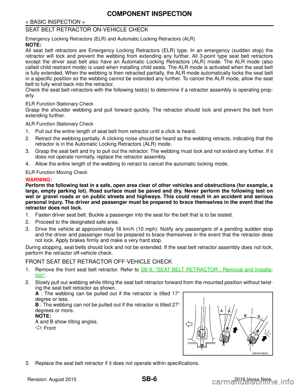
FRONT SEAT BELT RETRACTOR OFF-VEHICLE CHECK
1. Remove the front seat belt retractor. Refer to SB-9, "SEAT BELT RETRACTOR : Removal and Installa-
tion".
2. Slowly pull out webbing while tilting the seat belt re tractor forward from the mounted position without twist-
ing the seat belt retractor as shown.
A : The webbing can be pulled out if the retractor is tilted 17 °
degree or less.
B : The webbing can not be pulled out if the retractor is tilted 27°
degrees or more.
NOTE:
A and B show tilting angles.
: Front
3. Replace the seat belt retractor if it does not operate within specifications.
JMHIA1056ZZ
Revision: August 2015 2016 Versa Note
cardiagn.com
Page 2806 of 3641
FRONT SEAT BELTSB-9
< REMOVAL AND INSTALLATION >
C
DE
F
G
I
J
K L
M A
B
SB
N
O P
3. Remove seat belt buckle anchor bolt and the seat belt buckle. CAUTION:
Before removing the seat belt buckle anchor bolt , note the positions of washers and spacers for
correct installation.
INSTALLATION
Installation is in the reverse order of removal.
• Tighten the seat belt buckle anchor bolt to specification. Refer to SB-8, "
Exploded View".
• Always perform an inspection after repair to make sure the system is functioning within specifications. Refer
to SB-5, "
Inspection".
SEAT BELT RETRACTOR
SEAT BELT RETRACTOR : Removal and InstallationINFOID:0000000012430702
WARNING:
• Before servicing the SRS, turn the ignition switch off, disconnect both battery terminals then wait at
least three minutes.
• Do not drop the seat belt retractor. Always handle it with care.
• Always point pretensioner cylinder away from body when handling.
REMOVAL
1. Disconnect negative and positive battery terminals, then wait at least three minutes. Refer to PG-70,
"Removal and Installation (Battery)".
2. Slide front seat to the full forward position.
3. Remove center pillar lower finisher. Refer to INT-25, "
CENTER PILLAR LOWER FINISHER : Removal
and Installation".
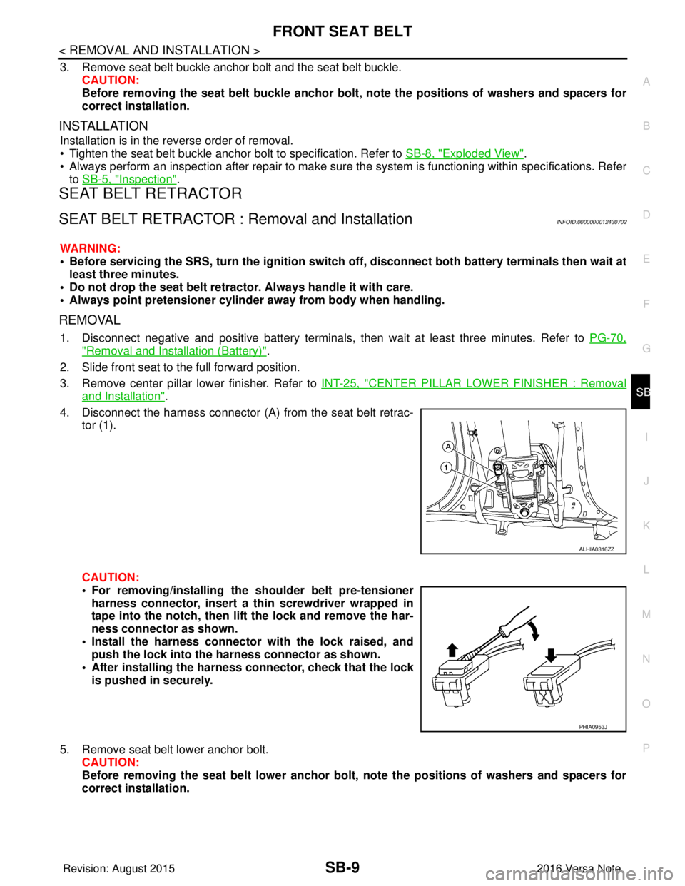
4. Disconnect the harness connector (A ) from the seat belt retrac-
tor (1).
CAUTION:
• For removing/installing the shoulder belt pre-tensioner
harness connector, insert a thin screwdriver wrapped in
tape into the notch, then lift the lock and remove the har-
ness connector as shown.
• Install the harness connector with the lock raised, and push the lock into the harness connector as shown.
• After installing the harness connector, check that the lock
is pushed in securely.
5. Remove seat belt lower anchor bolt. CAUTION:
Before removing the seat belt lower anchor bolt, note the positions of washers and spacers for
correct installation.
ALHIA0316ZZ
PHIA0953J
Revision: August 2015 2016 Versa Note
cardiagn.com
Page 2815 of 3641

SE-2
< PRECAUTION >
PRECAUTIONS
PRECAUTION
PRECAUTIONS
Precaution for Supplemental Restraint System (SRS) "AIR BAG" and "SEAT BELT
PRE-TENSIONER"
INFOID:0000000012432026
The Supplemental Restraint System such as “A IR BAG” and “SEAT BELT PRE-TENSIONER”, used along
with a front seat belt, helps to reduce the risk or severity of injury to the driver and front passenger for certain
types of collision. Information necessary to service the system safely is included in the SR and SB section of
this Service Manual.
WARNING:
• To avoid rendering the SRS inopera tive, which could increase the risk of personal injury or death in
the event of a collision which would result in air bag inflation, all maintenance must be performed by
an authorized NISSAN/INFINITI dealer.
• Improper maintenance, including in correct removal and installation of the SRS, can lead to personal
injury caused by unintent ional activation of the system. For re moval of Spiral Cable and Air Bag
Module, see the SR section.
• Do not use electrical test equipmen t on any circuit related to the SRS unless instructed to in this
Service Manual. SRS wiring harn esses can be identified by yellow and/or orange harnesses or har-
ness connectors.
PRECAUTIONS WHEN USING POWER TOOLS (AIR OR ELECTRIC) AND HAMMERS
WARNING:
• When working near the Airbag Diagnosis Sensor Unit or other Airbag System sensors with the Igni-
tion ON or engine running, DO NOT use air or electri c power tools or strike near the sensor(s) with a
hammer. Heavy vibration could activate the sensor( s) and deploy the air bag(s), possibly causing
serious injury.
• When using air or electric power tools or hammers , always switch the Ignition OFF, disconnect the
battery and wait at least three minutes before performing any service.
Precaution for WorkINFOID:0000000012432027
• When removing or disassembling each component, be careful not to damage or deform it. If a component may be subject to interference, be sure to protect it with a shop cloth.
• When removing (disengaging) components with a screwdriver or similar tool, be sure to wrap the component with a shop cloth or vinyl tape to protect it.
• Protect the removed parts with a shop cloth and prevent them from being dropped.
• Replace a deformed or damaged clip.
• If a part is specified as a non-reusable part, always replace it with a new one.
• Be sure to tighten bolts and nuts securely to the specified torque.
• After installation is complete, be sure to check that each part works properly.
• Follow the steps below to clean components:
- Water soluble dirt:
• Dip a soft cloth into lukewarm water, wring the water out of the cloth and wipe the dirty area.
• Then rub with a soft, dry cloth.
- Oily dirt:
• Dip a soft cloth into lukewarm water with mild detergent (concentration: within 2 to 3%) and wipe the dirty area.
• Then dip a cloth into fresh water, wring the water out of the cloth and wipe the detergent off.
• Then rub with a soft, dry cloth.
- Do not use organic solvent such as thinner, benzene, alcohol or gasoline.
- For genuine leather seats, use a genuine leather seat cleaner.
Revision: August 2015 2016 Versa Note
cardiagn.com
Page 2833 of 3641
SE-20
< REMOVAL AND INSTALLATION >
FRONT SEAT
DRIVER SIDE : Remova l and Installation
INFOID:0000000012432036
WARNING:
• Do not leave any objects (screwdriver s, tools, etc.) on the seat during repair. It can lead to personal
injury if the side air bag module should accidentally deploy.
• Always work from the side or back of th e seatback, do not work in front of seat.
• Do not use air tools or electric tools for servicing the seat.
• Do not drop, tilt, or bump the si de air bag module while installing the seat. Always handle it with
care.
• After the side air bag module inflates, the front seat frame must be replaced.
• Before removing the front seat, tu rn the ignition switch OFF, disconnect both battery cables then
wait at least three minutes.
CAUTION:
• When removing and installing the seat, use shop cloths to pr otect components from damage.
REMOVAL
1. Disconnect negative and positive battery terminals, then wait at least three minutes. Refer to PG-70,
"Removal and Installation (Battery)".
2. Slide the seat to the full forward position.
3. Remove the seat rear bolts.
4. Slide the seat to the full rearward position.
5. Remove the seat front bolts.
6. Tilt the seat rearward and disconnect the harness connectors from the seat and remove.
INSTALLATION
Installation is in the reverse order of removal.
CAUTION:
Make sure that the seat harness or the floor trim is not damaged during installation.
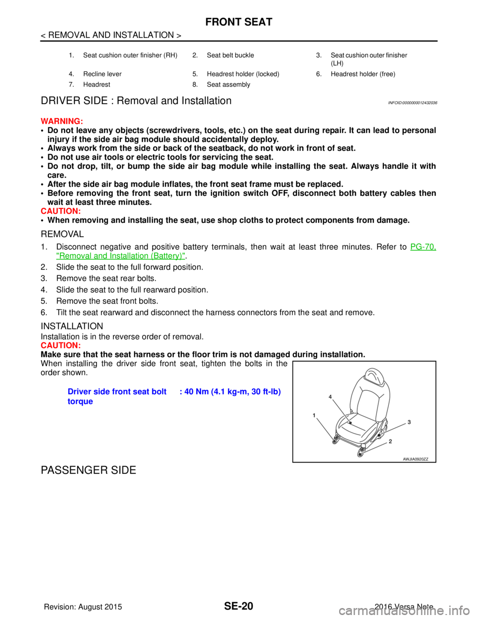
When installing the driver side front seat, tighten the bolts in the
order shown.
PASSENGER SIDE
1. Seat cushion outer finisher (RH) 2. Seat belt buckle 3. Seat cushion outer finisher
(LH)
4. Recline lever 5. Headrest holder (locked) 6. Headrest holder (free)
7. Headrest 8. Seat assembly
Driver side front seat bolt
torque: 40 Nm (4.1 kg-m, 30 ft-lb)
AWJIA0920ZZ
Revision: August 2015
2016 Versa Note
cardiagn.com
Page 2835 of 3641
SE-22
< REMOVAL AND INSTALLATION >
FRONT SEAT
PASSENGER SIDE : Remo val and Installation
INFOID:0000000012432038
WARNING:
• Do not leave any objects (screwdriver s, tools, etc.) on the seat during repair. It can lead to personal
injury if the side air bag module should accidentally deploy.
• Always work from the side or back of th e seatback, do not work in front of seat.
• Do not use air tools or electric tools for servicing the seat assembly.
• Do not drop, tilt, or bump the si de air bag module while installing the seat. Always handle it with
care.
• After the side air bag module inflates, the front seat frame must be replaced.
• Before removing the front seat, tu rn the ignition switch OFF, disconnect both battery cables then
wait at least three minutes.
CAUTION:
When removing and inst alling the seat, use shop cloths to protect components from damage.
REMOVAL
1. Disconnect negative and positive battery terminals, then wait at least three minutes. Refer to PG-70,
"Removal and Installation (Battery)".
2. Slide the seat to the full forward position.
3. Remove the seat rear bolts.
4. Slide the seat to the full rearward position.
5. Remove the seat front bolts.
6. Tilt the seat rearward and disconnect the harness connectors from the seat and remove.
INSTALLATION
Installation is in the reverse order of removal.
WARNING:
• Perform additional services when installing front passenger seat. Refer to SRC-39, "
ZERO POINT
RESET : Description".
• Zero point reset must be performed every time th e front passenger seat is removed from the vehicle.
• Zero point reset is done after the front passenger seat is installed in vehicle and all bolts are tight-
ened to specification.
CAUTION:
Make sure that the seat harness or the floor trim is not damaged during installation.
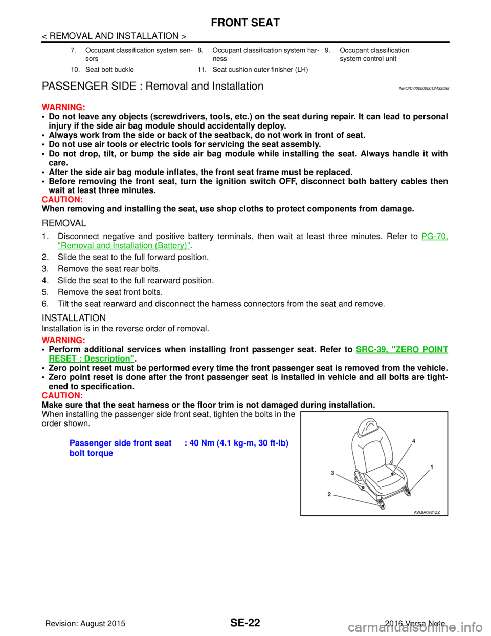
When installing the passenger side front seat, tighten the bolts in the
order shown.
7. Occupant classification system sen-
sors 8. Occupant classification system har-
ness 9. Occupant classification
system control unit
10. Seat belt buckle 11. Seat cushion outer finisher (LH)
Passenger side front seat
bolt torque: 40 Nm (4.1 kg-m, 30 ft-lb)
AWJIA0921ZZ
Revision: August 2015
2016 Versa Note
cardiagn.com
Page 2862 of 3641
![NISSAN NOTE 2016 Service Repair Manual PRECAUTIONSSEC-5
< PRECAUTION > [WITH INTELLIGENT KEY SYSTEM]
C
D
E
F
G H
I
J
L
M A
B
SEC
N
O P
PRECAUTION
PRECAUTIONS
Precaution for Supplemental Restraint System (SRS) "AIR BAG" and "SEAT BELT
PRE NISSAN NOTE 2016 Service Repair Manual PRECAUTIONSSEC-5
< PRECAUTION > [WITH INTELLIGENT KEY SYSTEM]
C
D
E
F
G H
I
J
L
M A
B
SEC
N
O P
PRECAUTION
PRECAUTIONS
Precaution for Supplemental Restraint System (SRS) "AIR BAG" and "SEAT BELT
PRE](/manual-img/5/57363/w960_57363-2861.png)
PRECAUTIONSSEC-5
< PRECAUTION > [WITH INTELLIGENT KEY SYSTEM]
C
D
E
F
G H
I
J
L
M A
B
SEC
N
O P
PRECAUTION
PRECAUTIONS
Precaution for Supplemental Restraint System (SRS) "AIR BAG" and "SEAT BELT
PRE-TENSIONER"
INFOID:0000000012430321
The Supplemental Restraint System such as “AIR BAG” and “SEAT BELT PRE-TENSIONER”, used along
with a front seat belt, helps to reduce the risk or severi ty of injury to the driver and front passenger for certain
types of collision. Information necessary to service the system safely is included in the SR and SB section of
this Service Manual.
WARNING:
• To avoid rendering the SRS inoper ative, which could increase the risk of personal injury or death in
the event of a collision which would result in air bag inflation, all maintenance must be performed by
an authorized NISSAN/INFINITI dealer.
• Improper maintenance, including in correct removal and installation of the SRS, can lead to personal
injury caused by unintentional act ivation of the system. For removal of Spiral Cable and Air Bag
Module, see the SR section.
• Do not use electrical test equipm ent on any circuit related to the SRS unless instructed to in this
Service Manual. SRS wiring harnesses can be identi fied by yellow and/or orange harnesses or har-
ness connectors.
PRECAUTIONS WHEN USING POWER TOOLS (AIR OR ELECTRIC) AND HAMMERS
WARNING:
• When working near the Airbag Diagnosis Sensor Un it or other Airbag System sensors with the Igni-
tion ON or engine running, DO NOT use air or el ectric power tools or strike near the sensor(s) with a
hammer. Heavy vibration could activate the sensor( s) and deploy the air bag(s), possibly causing
serious injury.
• When using air or electric power tools or hammers, always switch the Ignition OFF, disconnect the
battery and wait at least three mi nutes before performing any service.
Precaution for WorkINFOID:0000000012430322
• When removing or disassembling each component, be ca reful not to damage or deform it. If a component
may be subject to interference, be sure to protect it with a shop cloth.
• When removing (disengaging) components with a screwdriver or similar tool, be sure to wrap the component with a shop cloth or vinyl tape to protect it.
• Protect the removed parts with a shop cloth and prevent them from being dropped.
• Replace a deformed or damaged clip.
• If a part is specified as a non-reusabl e part, always replace it with a new one.
• Be sure to tighten bolts and nuts securely to the specified torque.
• After installation is complete, be sure to check that each part works properly.
• Follow the steps below to clean components:
- Water soluble dirt:
• Dip a soft cloth into lukewarm water, wring the water out of the cloth and wipe the dirty area.
• Then rub with a soft, dry cloth.
-Oily dirt:
• Dip a soft cloth into lukewarm water with mild detergent (concentration: within 2 to 3%) and wipe the dirty
area.
• Then dip a cloth into fresh water, wring the water out of the cloth and wipe the detergent off.
• Then rub with a soft, dry cloth.
- Do not use organic solvent such as thinner, benzene, alcohol or gasoline.
- For genuine leather seats, use a genuine leather seat cleaner.
Revision: August 2015 2016 Versa Note
cardiagn.com
Page 2865 of 3641
![NISSAN NOTE 2016 Service Repair Manual SEC-8
< SYSTEM DESCRIPTION >[WITH INTELLIGENT KEY SYSTEM]
COMPONENT PARTS
3. ABS actuator and electric unit (control unit) ABS actuator and electric unit (control unit)
transmits the vehicle speed si NISSAN NOTE 2016 Service Repair Manual SEC-8
< SYSTEM DESCRIPTION >[WITH INTELLIGENT KEY SYSTEM]
COMPONENT PARTS
3. ABS actuator and electric unit (control unit) ABS actuator and electric unit (control unit)
transmits the vehicle speed si](/manual-img/5/57363/w960_57363-2864.png)
SEC-8
< SYSTEM DESCRIPTION >[WITH INTELLIGENT KEY SYSTEM]
COMPONENT PARTS
3. ABS actuator and electric unit (control unit) ABS actuator and electric unit (control unit)
transmits the vehicle speed signal to BCM via
CAN communication.
BCM also receives the vehicle speed signal
from the combination meter via CAN commu-
nication. BCM compares both signals to de-
tect the vehicle speed.
Refer to
BRC-8, "
ABS Actuator and Electric
Unit (Control Unit)" for detailed installation lo-
cation.
4. Intelligent Key warning buzzer Intelligent Key warning buzzer warns the us-
er, who is outside the vehicle, of operation
confirmation according to Intelligent Key op-
eration and door request switch operation, or
of an inappropriate operation.
5. Transmission range switch Transmission range switch detects the CVT
shift selector lever position.
6. IPDM E/R Starter control relay is integrated in IPDM E/R
and used for the engine starting function.
Starter relay is controlled by BCM, and starter
control relay is controlled by IPDM E/R while
communicating with BCM. IPDM E/R sends
the starter control rela
y and starter relay sta-
tus signal to BCM.
7. BCM BCM controls INTELLIGENT KEY SYSTEM
(ENGINE START FUNCTION), NISSAN VE-
HICLE IMMOBILIZER SYSTEM-NATS [NVIS
(NATS)] and VEHICLE SECURITY SYSTEM.
BCM performs the ID verification between
BCM and Intelligent Key when the Intelligent
Key is carried into the detection area of inside
key antenna, and push-button ignition switch
is pressed. If the ID verification result is OK,
ignition switch operation is available.
Then, when the ignition switch is turned ON,
BCM performs ID verification between BCM
and ECM. If the ID verification result is OK,
ECM can start engine.
Refer to
BCS-6, "
BODY CONTROL SYSTEM
: Component Parts Location" for detailed in-
stallation location.
8. Clutch interlock switch Clutch interlock switch detects that clutch
pedal is depressed, and then transmits ON/
OFF signal to the BCM.
9. Stop lamp switch Stop lamp switch detects that brake pedal is
depressed, and then transmits ON/OFF sig-
nal to the BCM.
10. Main power window and door lock/unlock switch Door lock and unlock switch is integrated into
the main power window and door lock/unlock
switch.
Door lock and unlock switch transmits door
lock/unlock operation signal to BCM.
Refer to
PWC-7, "
Main Power Window And
Door Lock/Unlock Switch".
11. CVT shift selector (park position switch) Park position switch is integrated into the
CVT shift selector and detects that the selec-
tor lever is in the P (park) position, then trans-
mits ON/OFF signal to the BCM and IPDM E/
R.
No.
Component Function
Revision: August 2015 2016 Versa Note
cardiagn.com