2016 NISSAN NOTE low beam
[x] Cancel search: low beamPage 357 of 3641
![NISSAN NOTE 2016 Service Repair Manual BCS-96
< SYSTEM DESCRIPTION >[WITHOUT INTELLIGENT KEY SYSTEM]
DIAGNOSIS SYSTEM (BCM)
COMB SW
COMB SW : CONSULT Function (BCM - COMB SW)INFOID:0000000012432380
DATA MONITOR
BCM
BCM : CONSULT Function (](/manual-img/5/57363/w960_57363-356.png "NISSAN NOTE 2016 Service Repair Manual BCS-96
< SYSTEM DESCRIPTION >[WITHOUT INTELLIGENT KEY SYSTEM]
DIAGNOSIS SYSTEM (BCM)
COMB SW
COMB SW : CONSULT Function (BCM - COMB SW)INFOID:0000000012432380
DATA MONITOR
BCM
BCM : CONSULT Function (")
BCS-96
< SYSTEM DESCRIPTION >[WITHOUT INTELLIGENT KEY SYSTEM]
DIAGNOSIS SYSTEM (BCM)
COMB SW
COMB SW : CONSULT Function (BCM - COMB SW)INFOID:0000000012432380
DATA MONITOR
BCM
BCM : CONSULT Function (BCM - BCM)INFOID:0000000012432381
ECU IDENTIFICATION
The BCM part number is displayed.
SELF DIAGNOSTIC RESULT
Refer to
BCS-115, "DTCIndex".
WORK SUPPORT
CONFIGURATION
Refer to BCS-123, "Description".
CAN DIAG SUPPORT MNTR
Refer to LAN-13, "CAN Diagnostic Support Monitor".
IMMU
Monitor Item [Unit] Description
IGN ON SW [On/Off] Indicates condition of ignition switch ON position.
FAN ON SIG [On/Off] Indicates condition of fan switch.
AIR COND SW [On/Off] Indicates condition of A/C switch.
THERMO AMP [On/Off] Indicates condition of thermo amp.
FR DEF SW [On/Off] Indicates condition of front defrost switch.
Monitor Item [Unit] Description
TURN SIGNAL R [On/Off] Indicates condition of right turn signal operation of combination switch.
TURN SIGNAL L [On/Off] Indicates condition of left turn signal operation of combination switch.
HI BEAM SW [On/Off] Indicates condition of Hi beam switch operation of combination switch.
HEAD LAMP SW 1 [On/Off] Indicates condition of head lamp switch 1 operation of combination switch.
HEAD LAMP SW 2 [On/Off] Indicates condition of head lamp switch 2 operation of combination switch.
TAIL LAMP SW [On/Off] Indicates condition of tail lamp switch operation of combination switch.
PASSING SW [On/Off] Indicates condition of passing switch operation of combination switch.
FR FOG SW [On/Off] Indicates condition of front fog lamp switch operation of combination switch.
FR WIPER HI [On/Off]
Indicates condition of front wiper operation of combination switch.
FR WIPER LOW [On/Off]
FR WIPER INT [On/Off]
FR WASHER SW [On/Off]
INT VOLUME [1 - 7]
Indicates condition of intermittent front wiper operation of combination switch.
RR WIPER ON [On/Off] Indicates condition of rear wiper operation of combination switch.
RR WIPER INT [On/Off]
RR WASHER SW [On/Off]
Support Item Setting Description
RESET SETTING VALUE Reset Returns BCM to initial value in factory shipment.
Cancel Cancels the reset function.
Revision: August 2015
2016 Versa Note
cardiagn.com
Page 363 of 3641
![NISSAN NOTE 2016 Service Repair Manual BCS-102
< ECU DIAGNOSIS INFORMATION >[WITHOUT INTELLIGENT KEY SYSTEM]
BCM
FAN O N SIGBlower fan OFF
Off
Blower fan ON On
FR FOG SW Front fog lamp switch OFF
Off
Front fog lamp switch ON On
FR WASHER](/manual-img/5/57363/w960_57363-362.png "NISSAN NOTE 2016 Service Repair Manual BCS-102
< ECU DIAGNOSIS INFORMATION >[WITHOUT INTELLIGENT KEY SYSTEM]
BCM
FAN O N SIGBlower fan OFF
Off
Blower fan ON On
FR FOG SW Front fog lamp switch OFF
Off
Front fog lamp switch ON On
FR WASHER")
BCS-102
< ECU DIAGNOSIS INFORMATION >[WITHOUT INTELLIGENT KEY SYSTEM]
BCM
FAN O N SIGBlower fan OFF
Off
Blower fan ON On
FR FOG SW Front fog lamp switch OFF
Off
Front fog lamp switch ON On
FR WASHER SW Front washer switch OFF
Off
Front washer switch ON On
FR WIPER LOW Front wiper switch OFF
Off
Front wiper switch LO On
FR WIPER HI Front wiper switch OFF
Off
Front wiper switch HI On
FR WIPER INT Front wiper switch OFF
Off
Front wiper switch INT On
FR WIPER STOP Any position other than front wiper stop position
Off
Front wiper stop position On
HAZARD SW Hazard switch OFF
Off
Hazard switch ON On
HEAD LAMP SW 1 Lighting switch OFF
Off
Lighting switch 1ST On
HEAD LAMP SW 2 Lighting switch OFF
Off
Lighting switch 2ND On
HI BEAM SW Lighting switch OFF
Off
Lighting switch HI On
ID REGST FL1 ID registration of front left tire incomplete
Yet
ID registration of front left tire complete Done
ID REGST FR1 ID registration of front right tire incomplete
Yet
ID registration of front right tire complete Done
ID REGST RL1 ID registration of rear left tire incomplete
Yet
ID registration of rear left tire complete Done
ID REGST RR1 ID registration of rear right tire incomplete
Yet
ID registration of rear right tire complete Done
IGN ON SW Ignition switch OFF or ACC
Off
Ignition switch ON On
IGN SW CAN Ignition switch OFF or ACC
Off
Ignition switch ON On
INT VOLUME Intermittent front wiper position 1 - 7
KEY CYL LK-SW Key cylinder switch in N position
Off
Key cylinder switch in LOCK position On
KEY CYL UN-SW Key cylinder switch in N position
Off
Key cylinder switch in UNLOCK position On
KEY ON SW Key removed from ignition key cylinder
Off
Key inserted into ignition key cylinder On
KEYLESS LOCK LOCK button of keyfob not pressed
Off
LOCK button of keyfob pressed On
Monitor Item
ConditionValue/Status
Revision: August 2015 2016 Versa Note
cardiagn.com
Page 395 of 3641
![NISSAN NOTE 2016 Service Repair Manual BCS-134
< SYMPTOM DIAGNOSIS >[WITHOUT INTELLIGENT KEY SYSTEM]
COMBINATION SWITCH SYSTEM SYMPTOMS
SYMPTOM DIAGNOSIS
COMBINATION SWITCH SYSTEM SYMPTOMS
Symptom TableINFOID:0000000012432409
WITH VARIABLE](/manual-img/5/57363/w960_57363-394.png "NISSAN NOTE 2016 Service Repair Manual BCS-134
< SYMPTOM DIAGNOSIS >[WITHOUT INTELLIGENT KEY SYSTEM]
COMBINATION SWITCH SYSTEM SYMPTOMS
SYMPTOM DIAGNOSIS
COMBINATION SWITCH SYSTEM SYMPTOMS
Symptom TableINFOID:0000000012432409
WITH VARIABLE")
BCS-134
< SYMPTOM DIAGNOSIS >[WITHOUT INTELLIGENT KEY SYSTEM]
COMBINATION SWITCH SYSTEM SYMPTOMS
SYMPTOM DIAGNOSIS
COMBINATION SWITCH SYSTEM SYMPTOMS
Symptom TableINFOID:0000000012432409
WITH VARIABLE INTERMITTENT FRONT WIPERS
1. Perform the data monitor of CONSULT
to check for any malfunctioning item.
2. Check the malfunction combinations.
Malfunction item: ×
3. Identify the malfunctioning part from the agreed combination and repair or replace the part.
WITHOUT VARIABLE INTERMITTENT FRONT WIPERS
1. Perform the data monitor of CONSULT to check for any malfunctioning item.
Malfunction combination Data monitor item
FR WIPER HI
FR WIPER LOW
FR WASHER SW FR WIPER INTINT VOLUME
RR WIPER ON
RR WIPER INT
RR WASHER SW TURN SIGNAL RTURN SIGNAL L TA I L L A M P S W HI BEAM SW
HEAD LAMP SW 1
HEAD LAMP SW 2 PA S S I N G S WFR FOG SW
A ×× ××
B ×× ××
C ×× ××
D ×××
E ×× ×
F ×× ×
G ××××
H ××
I ××××
J × ×××
K All Items
L If only one item is detected or the item is not applicable to the combinations A to K
Malfunction
combination Malfunctioning part
Repair or replace
A Combination switch INPUT 1 circuit
Inspect the combination switch input circuit applicable to the malfunctioning
part. Refer to BCS-130, "
Diagnosis Procedure".
B Combination switch INPUT 2 circuit
C Combination switch INPUT 3 circuit
D Combination switch INPUT 4 circuit E Combination switch INPUT 5 circuitF Combination switch OUTPUT 1 circuit
Inspect the combination switch output circuit applicable to the malfunction-
ing part. Refer to BCS-132, "
Diagnosis Procedure".
G Combination switch OUTPUT 2 circuit
H Combination switch OUTPUT 3 circuit I Combination switch OUTPUT 4 circuit
J Combination switch OUTPUT 5 circuit
K BCM Replace BCM. Refer to BCS-137, "
Removal and Installation".
L Combination switch Replace the combination switch. Refer to
BCS-138, "
Removal and Installa-
tion".
Revision: August 2015 2016 Versa Note
cardiagn.com
Page 396 of 3641
![NISSAN NOTE 2016 Service Repair Manual BCS
COMBINATION SWITCH SYSTEM SYMPTOMSBCS-135
< SYMPTOM DIAGNOSIS > [WITHOUT INTELLIGENT KEY SYSTEM]
C
D
E
F
G H
I
J
K L
B A
O P
N
2. Check the malfunction combinations.
Malfunction item:
×
3. Ident](/manual-img/5/57363/w960_57363-395.png "NISSAN NOTE 2016 Service Repair Manual BCS
COMBINATION SWITCH SYSTEM SYMPTOMSBCS-135
< SYMPTOM DIAGNOSIS > [WITHOUT INTELLIGENT KEY SYSTEM]
C
D
E
F
G H
I
J
K L
B A
O P
N
2. Check the malfunction combinations.
Malfunction item:
×
3. Ident")
BCS
COMBINATION SWITCH SYSTEM SYMPTOMSBCS-135
< SYMPTOM DIAGNOSIS > [WITHOUT INTELLIGENT KEY SYSTEM]
C
D
E
F
G H
I
J
K L
B A
O P
N
2. Check the malfunction combinations.
Malfunction item:
×
3. Identify the malfunctioning part from the agreed combination and repair or replace the part.
Malfunction combination Data monitor item
FR WIPER HI
FR WIPER LOW
FR WASHER SW
FR WIPER INT
RR WIPER ON
RR WIPER INT
RR WASHER SW TURN SIGNAL R
TURN SIGNAL L TAIL LAMP SW HI BEAM SW
HEAD LAMP SW 1
HEAD LAMP SW 2 PASSING SW
A ×× ××
B ×× ××
C ×××
D ××
E ×
F ××
G ×××
H ××
I ×××
J ××××
K All Items
L If only one item is detected or the item is not applicable to the combinations A to K
Malfunction
combination Malfunctioning part
Repair or replace
A Combination switch INPUT 1 circuit
Inspect the combination switch input circuit applicable to the malfunctioning
part. Refer to BCS-130, "
Diagnosis Procedure".
B Combination switch INPUT 2 circuit
C Combination switch INPUT 3 circuit
D Combination switch INPUT 4 circuit E Combination switch INPUT 5 circuitF Combination switch OUTPUT 1 circuit
Inspect the combination switch output circuit applicable to the malfunction-
ing part. Refer to BCS-132, "
Diagnosis Procedure".
G Combination switch OUTPUT 2 circuit
H Combination switch OUTPUT 3 circuit I Combination switch OUTPUT 4 circuit
J Combination switch OUTPUT 5 circuit
K BCM Replace BCM. Refer to BCS-137, "
Removal and Installation".
L Combination switch Replace the combination switch. Refer to
BCS-138, "
Removal and Installa-
tion".
Revision: August 2015 2016 Versa Note
cardiagn.com
Page 1654 of 3641

EXL-2
FLASHER : CONSULT Function (BCM - FLASH-
ER) .........................................................................
17
COMB SW .............................................................. ...18
COMB SW : CONSULT Function (BCM - COMB
SW) .........................................................................
18
BATTERY SAVER ................................................. ...18
BATTERY SAVER : CONSULT Function (BCM -
BATTERY SAVER) .................................................
18
DIAGNOSIS SYSTEM (IPDM E/R) ................. ...20
Diagnosis Description .......................................... ...20
CONSULT Function (IPDM E/R) ............................21
ECU DIAGNOSIS INFORMATION ..............24
BCM, IPDM E/R .............................................. ...24
List of ECU Reference ......................................... ...24
WIRING DIAGRAM .....................................25
HEADLAMP .................................................... ...25
Wiring Diagram - For USA ................................... ...25
Wiring Diagram - For Canada .................................31
DAYTIME LIGHT SYSTEM ............................. ...37
Wiring Diagram .................................................... ...37
FRONT FOG LAMP ...........................................43
Wiring Diagram .................................................... ...43
TURN SIGNAL AND HAZARD WARNING
LAMP SYSTEM .............................................. ...
48
Wiring Diagram .................................................... ...48
PARKING, LICENSE PLATE AND TAIL
LAMPS SYSTEM ............................................ ...
55
Wiring Diagram .................................................... ...55
STOP LAMP ......................................................63
Wiring Diagram .................................................... ...63
BACK-UP LAMP ................................................67
Wiring Diagram .................................................... ...67
BASIC INSPECTION ...................................71
DIAGNOSIS AND REPAIR WORKFLOW ...... ...71
Work Flow ............................................................ ...71
DTC/CIRCUIT DIAGNOSIS ...................... ...74
POWER SUPPLY AND GROUND CIRCUIT .. ...74
BCM (BODY CONTROL SYSTEM) (WITH INTEL-
LIGENT KEY SYSTEM) ..... .......................................
74
BCM (BODY CONTROL S YSTEM) (WITH INTEL-
LIGENT KEY SYSTEM) : Dia gnosis Procedure .....
74
BCM (BODY CONTROL SYST EM) (WITHOUT IN-
TELLIGENT KEY SYSTEM) . ....................................
74
BCM (BODY CONTROL SYSTEM) (WITHOUT
INTELLIGENT KEY SYSTEM) : Diagnosis Proce-
dure ...................................................................... ...
74
IPDM E/R ................................................................ ...75
IPDM E/R : Diagnosis Procedure ............................75
HEADLAMP (HI) CIRCUIT ................................77
Description ........................................................... ...77
Component Function Check ...................................77
Diagnosis Procedure ...............................................77
HEADLAMP (LO) CIRCUIT ...............................79
Description ........................................................... ...79
Component Function Check ...................................79
Diagnosis Procedure ...............................................79
PARKING LAMP CIRCUIT ................................82
Description ........................................................... ...82
Component Function Check ...................................82
Diagnosis Procedure ...............................................82
TURN SIGNAL LAMP CIRCUIT ........................85
Description ........................................................... ...85
Component Function Check ...................................85
Diagnosis Procedure ...............................................85
FRONT FOG LAMP CIRCUIT ...........................88
Component Function Check ................................ ...88
Diagnosis Procedure ...............................................88
Component Inspection ............................................90
SYMPTOM DIAGNOSIS ............................91
EXTERIOR LIGHTING SYSTEM SYMPTOMS ...91
Symptom Table .................................................... ...91
BOTH SIDE HEADLAMPS DO NOT SWITCH
TO HIGH BEAM .................................................
93
Description ........................................................... ...93
Diagnosis Procedure ...............................................93
BOTH SIDE HEADLAMPS (LO) ARE NOT
TURNED ON ......................................................
94
Description ..............................................................94
Diagnosis Procedure ...............................................94
PARKING, LICENSE PLATE AND TAIL
LAMPS ARE NOT TURNED ON .......................
95
Description ........................................................... ...95
Diagnosis Procedure ...............................................95
BOTH SIDE FRONT FOG LAMPS ARE NOT
TURNED ON ......................................................
96
Description ..............................................................96
Diagnosis Procedure ...............................................96
PERIODIC MAINTENANCE .......................97
HEADLAMP AIMING ADJUSTMENT ............ ...97
Inspection ............................................................. ...97
Aiming Adjustment Procedure ................................98
Revision: August 2015 2016 Versa Note
cardiagn.com
Page 1660 of 3641
EXL-8
< SYSTEM DESCRIPTION >
SYSTEM
SYSTEM
HEADLAMP SYSTEM
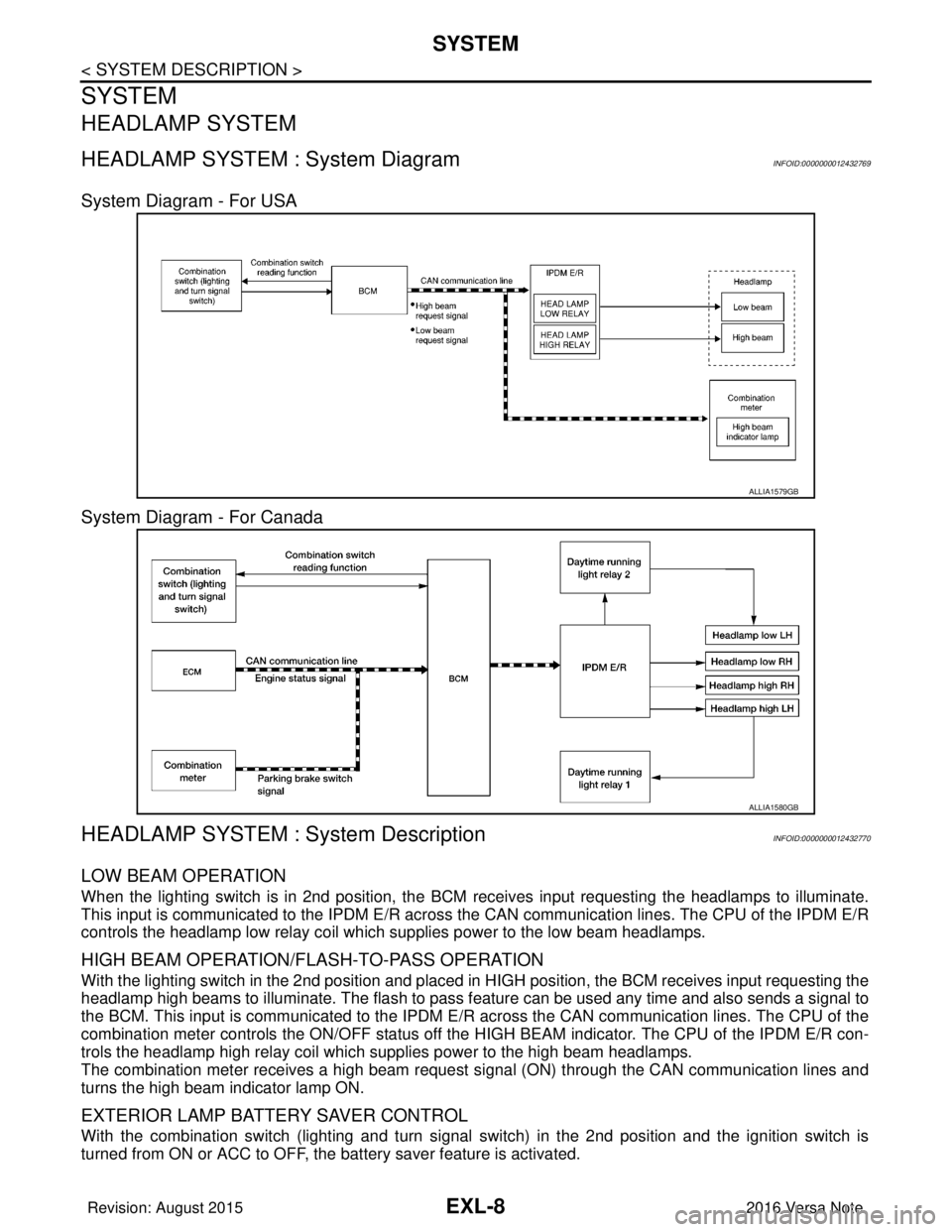
HEADLAMP SYSTEM : System Diagram INFOID:0000000012432769
System Diagram - For USA
System Diagram - For Canada
HEADLAMP SYSTEM : System DescriptionINFOID:0000000012432770
LOW BEAM OPERATION
When the lighting switch is in 2nd position, the BCM receives input requesting the headlamps to illuminate.
This input is communicated to the IPDM E/R across the CAN communication lines. The CPU of the IPDM E/R
controls the headlamp low relay coil which supplies power to the low beam headlamps.
HIGH BEAM OPERATION/FLASH-TO-PASS OPERATION
With the lighting switch in the 2nd position and placed in HIGH position, the BCM receives input requesting the
headlamp high beams to illuminate. The flash to pass f eature can be used any time and also sends a signal to
the BCM. This input is communicated to the IPDM E/R across the CAN communication lines. The CPU of the
combination meter controls the ON/OFF status off the HIGH BEAM indicator. The CPU of the IPDM E/R con-
trols the headlamp high relay coil which supplies power to the high beam headlamps.
The combination meter receives a high beam request signal (ON) through the CAN communication lines and
turns the high beam indicator lamp ON.
EXTERIOR LAMP BATTERY SAVER CONTROL
With the combination switch (lighting and turn signal switch) in the 2nd position and the ignition switch is
turned from ON or ACC to OFF, the battery saver feature is activated.
ALLIA1579GB
ALLIA1580GB
Revision: August 2015 2016 Versa Note
cardiagn.com
Page 1661 of 3641

SYSTEMEXL-9
< SYSTEM DESCRIPTION >
C
DE
F
G H
I
J
K
M A
B
EXL
N
O P
Under this condition, the headlamps remain illuminated for 45 seconds unless the lighting switch position is
changed. If the lighting switch position is changed, then the headlamps are turned off.
This setting can be changed by CONSULT. Refer to BCS-20, "
HEADLAMP : CONSULT Function (BCM -
HEAD LAMP)" (with Intelligent Key system) or BCS-93, "HEADLAMP : CONSULT Function (BCM - HEAD
LAMP)" (without Intelligent Key system).
DAYTIME RUNNING LIGHT SYSTEM
DAYTIME RUNNING LIGHT SYSTEM : System DiagramINFOID:0000000012432771
DAYTIME RUNNING LIGHT SYST EM : System DescriptionINFOID:0000000012432772
The headlamp system is equipped with a daytime running light control that activates the high beam head-
lamps at approximately half illumination whenever the e ngine is operating. If the parking brake is applied
before the engine is started the daytime running lights will not be illuminated. The daytime running lights will
illuminate once the parking brake is released. Thereaf ter, the daytime running lights will continue to operate
when the parking brake is applied.
OPERATION
The BCM monitors inputs from the parking brake swit ch and the combination switch (lighting and turn signal
switch) to determine when to activate the daytime running light system. The BCM sends a daytime running
light request to the IPDM E/R via the CAN communication lines. The IPDM E/R grounds the daytime running
light relay 1 which in turn, provides power to the LH high beam lamp. Power flows through the LH high beam
lamp to the RH high beam lamp. The high beam lamps are wired in series which causes them to illuminate at
a reduced intensity. When daytime light relay 2 is open, it prevents headlamp low beam from turning on while
daytime running lights are operating.
FRONT FOG LAMP SYSTEM
FRONT FOG LAMP SYSTEM : System DiagramINFOID:0000000012432773
ALLIA1577GB
ALLIA1578GB
Revision: August 2015 2016 Versa Note
cardiagn.com
Page 1665 of 3641

DIAGNOSIS SYSTEM (BCM) (WITH INTELLIGENT KEY SYSTEM)
EXL-13
< SYSTEM DESCRIPTION >
C
D E
F
G H
I
J
K
M A
B
EXL
N
O P
HEADLAMP
HEADLAMP : CONSULT Function (BCM - HEAD LAMP)INFOID:0000000012542303
DATA MONITOR
ACTIVE TEST
WORK SUPPORT
*: Initial setting
FLASHER
Monitor Item [Unit] Description
PUSH SW [On/Off] Indicates condition of push-button ignition switch.
ENGINE STATE [Stop/Stall/Crank/Run] Indicates engine status received from ECM on CAN communication line.
VEH SPEED 1 [km/h] Indicates vehicle speed signal received from ABS on CAN communication line.
TURN SIGNAL R [On/Off]
Indicates condition of combination switch.
TURN SIGNAL L [On/Off]
TAIL LAMP SW [On/Off]
HI BEAM SW [On/Off]
HEAD LAMP SW 1 [On/Off]
HEAD LAMP SW 2 [On/Off]
PASSING SW [On/Off]
FR FOG SW [On/Off]
DOOR SW-DR [On/Off]
Indicates condition of front door switch LH.
DOOR SW-AS [On/Off] Indicates condition of front door switch RH.
DOOR SW-RR [On/Off] Indicates condition of rear door switch RH.
DOOR SW-RL [On/Off] Indicates condition of rear door switch LH.
DOOR SW-BK [On/Off] Indicates condition of back door switch.
Test Item Description
FR FOG LAMP This test is able to check front fog lamp operation [On/Off].
HEAD LAMP This test is able to check head lamp operation [Hi/Low/Off].
ILL DIM SIGNAL This test is able to check head lamp illumination dimming operation [On/Off].
TAIL LAMP This test is able to check tail lamp operation [On/Off].
Support ItemSetting Description
BATTERY SAVER SET On*
Exterior lamp battery saver function ON.
Off Exterior lamp battery saver function OFF.
ILL DELAY SET MODE 8 180 sec.
Sets delay timer function operation time
(All doors closed).
MODE 7 150 sec.
MODE 6 120 sec.
MODE 4 60 sec.
MODE 5 90 sec.
MODE 3 30 sec.
MODE 2 OFF
MODE 1* 45 sec.
Revision: August 2015
2016 Versa Note
cardiagn.com