Page 630 of 3641
CL-4
< SYMPTOM DIAGNOSIS >
NOISE, VIBRATION AND HARSHNESS (NVH) TROUBLESHOOTING
SYMPTOM DIAGNOSIS
NOISE, VIBRATION AND HARSHNESS (NVH) TROUBLESHOOTING
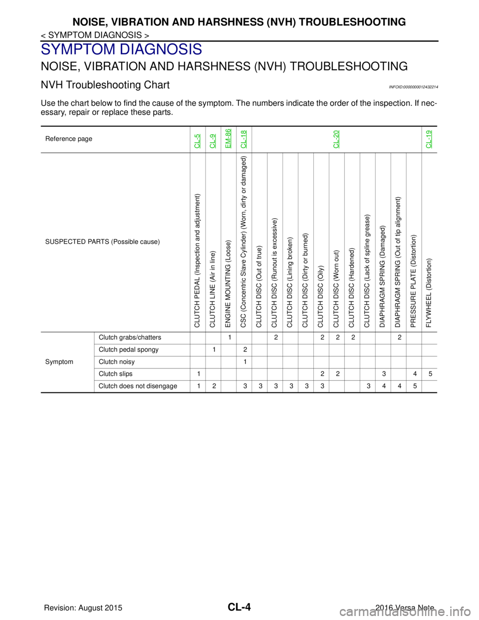
NVH Troubleshooting ChartINFOID:0000000012432214
Use the chart below to find the cause of the symptom. T he numbers indicate the order of the inspection. If nec-
essary, repair or replace these parts.
Reference pageCL-5CL-9EM-86CL-18CL-20CL-19
SUSPECTED PARTS (Possible cause)
CLUTCH PEDAL (Inspection and adjustment)
CLUTCH LINE (Air in line)
ENGINE MOUNTING (Loose)
CSC (Concentric Slave Cylinder) (Worn, dirty or damaged)
CLUTCH DISC (Out of true)
CLUTCH DISC (Ru nout is excessive)
CLUTCH DISC (Lining broken)
CLUTCH DISC (Dirty or burned)
CLUTCH DISC (Oily)
CLUTCH DISC (Worn out)
CLUTCH DISC (Hardened)
CLUTCH DISC (Lack of spline grease)
DIAPHRAGM SPRING (Damaged)
DIAPHRAGM SPRING (Out of tip alignment)
PRESSURE PLATE (Distortion)
FLYWHEEL (Distortion)
Symptom Clutch grabs/chatters
122 2 2 2
Clutch pedal spongy 1 2
Clutch noisy 1
Clutch slips 1 2 23 4 5
Clutch does not disengage 12 333333 3445
Revision: August 2015 2016 Versa Note
cardiagn.com
Page 631 of 3641
CLUTCH PEDALCL-5
< PERIODIC MAINTENANCE >
CEF
G H
I
J
K L
M A
B
CL
N
O P
PERIODIC MAINTENANCE
CLUTCH PEDAL
Inspection and AdjustmentINFOID:0000000012432215
INSPECTION
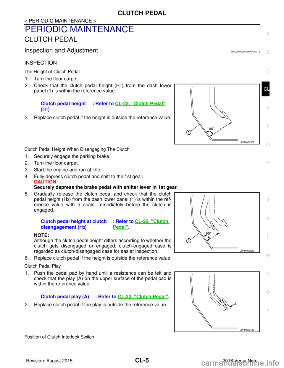
The Height of Clutch Pedal
1. Turn the floor carpet.
2. Check that the clutch pedal height (H
1) from the dash lower
panel (1) is within the reference value.
3. Replace clutch pedal if the height is outside the reference value.
Clutch Pedal Height When Disengaging The Clutch
1. Securely engage the parking brake.
2. Turn the floor carpet.
3. Start the engine and run at idle.
4. Fully depress clutch pedal and shift to the 1st gear. CAUTION:
Securely depress the brake pedal with shifter lever in 1st gear.
5. Gradually release the clutch pedal and check that the clutch pedal height (H
2) from the dash lower panel (1) is within the ref-
erence value with a scale immediately before the clutch is
engaged.
NOTE:
Although the clutch pedal height differs according to whether the
clutch gets disengaged or engaged, clutch-engaged case is
regarded as clutch-disengaged case for easier inspection.
6. Replace clutch pedal if the height is outside the reference value.
Clutch Pedal Play
1. Push the pedal pad by hand until a resistance can be felt and check that the play (A) on the upper surface of the pedal pad is
within the reference value.
2. Replace clutch pedal if the play is outside the reference value.
Position of Clutch Interlock Switch
Clutch pedal height
(H
1) : Refer to
CL-22, "
Clutch Pedal".
JPFIA0065ZZ
Clutch pedal height at clutch
disengagement (H
2) : Refer to CL-22, "
Clutch
Pedal".
JPFIA0068ZZ
Clutch pedal play (A) : Refer to
CL-22, "Clutch Pedal".
JPFIA0121ZZ
Revision: August 2015 2016 Versa Note
cardiagn.com
Page 632 of 3641
CL-6
< PERIODIC MAINTENANCE >
CLUTCH PEDAL
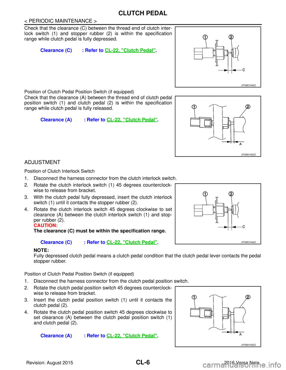
Check that the clearance (C) between the thread end of clutch inter-
lock switch (1) and stopper rubber (2) is within the specification
range while clutch pedal is fully depressed.
Position of Clutch Pedal Position Switch (if equipped)
Check that the clearance (A) between the thread end of clutch pedal
position switch (1) and clutch pedal (2) is within the specification
range while clutch pedal is fully released.
ADJUSTMENT
Position of Clutch Interlock Switch
1. Disconnect the harness connector from the clutch interlock switch.
2. Rotate the clutch interlock switch (1) 45 degrees counterclock- wise to release from bracket.
3. With the clutch pedal fully depressed, insert the clutch interlock switch (1) until it contacts the stopper rubber (2).
4. Rotate the clutch interlock switch 45 degrees clockwise to set clearance (A) between the clutch interlock switch (1) and stop-
per rubber (2).
CAUTION:
The clearance (C) must be wi thin the specification range.
NOTE:
Fully depressed clutch pedal means a clutch pedal condi tion that the clutch pedal lever contacts the pedal
stopper rubber.
Position of Clutch Pedal Position Switch (if equipped)
1. Disconnect the harness connector from the clutch pedal position switch.
2. Rotate the clutch pedal position switch 45 degrees counterclock- wise to release from bracket.
3. Insert the clutch pedal position switch (1) until it contacts the
clutch pedal (2).
4. Rotate the clutch pedal position switch 45 degrees clockwise to set clearance (A) between the clutch pedal position switch (1)
and clutch pedal (2).Clearance (C) : Refer to
CL-22, "
Clutch Pedal".
JPDIB0164ZZ
Clearance (A) : Refer to CL-22, "Clutch Pedal".
JPDIB0165ZZ
Clearance (C) : Refer to CL-22, "Clutch Pedal".JPDIB0164ZZ
Clearance (A) : Refer to CL-22, "Clutch Pedal".
JPDIB0165ZZ
Revision: August 2015 2016 Versa Note
cardiagn.com
Page 633 of 3641
CLUTCH FLUIDCL-7
< PERIODIC MAINTENANCE >
CEF
G H
I
J
K L
M A
B
CL
N
O P
CLUTCH FLUID
InspectionINFOID:0000000012432216
CLUTCH FLUID LEAKS
• Check clutch line for cracks, deterioration or other damage. Replace any damaged parts.
• Check for clutch fluid leaks by fully depressing clutch pedal while engine is running. CAUTION:
If leaks occur around connections, reinstall th e lines or replace damaged parts, if necessary.
CLUTCH FLUID LEVEL
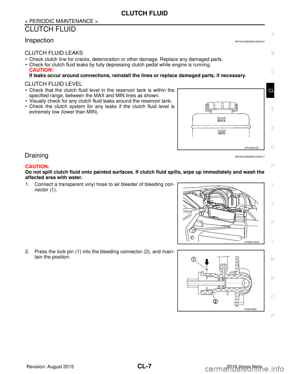
• Check that the clutch fluid level in the reservoir tank is within the
specified range, between the MAX and MIN lines as shown.
• Visually check for any clutch fluid leaks around the reservoir tank.
• Check the clutch system for any leaks if the clutch fluid level is
extremely low (lower than MIN).
DrainingINFOID:0000000012432217
CAUTION:
Do not spill clutch fluid onto painted surfaces. If clutch fluid spills, wipe up immediately and wash the
affected area with water.
1. Connect a transparent vinyl hose to air bleeder of bleeding con-
nector (1).
2. Press the lock pin (1) into the bleeding connector (2), and main- tain the position.
JPFIA0007ZZ
JPDIB0144ZZ
PCIB1495E
Revision: August 2015 2016 Versa Note
cardiagn.com
Page 634 of 3641
CL-8
< PERIODIC MAINTENANCE >
CLUTCH FLUID
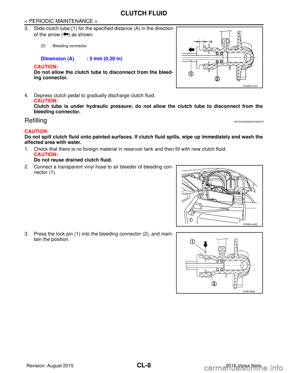
3. Slide clutch tube (1) for the specified distance (A) in the directionof the arrow ( ) as shown.
CAUTION:
Do not allow the clutch tube to disconnect from the bleed-
ing connector.
4. Depress clutch pedal to gradually discharge clutch fluid. CAUTION:
Clutch tube is under hydraulic pressure; do not allow the clutch tube to disconnect from the
bleeding connector.
RefillingINFOID:0000000012432218
CAUTION:
Do not spill clutch fluid onto painted surfaces. If cl utch fluid spills, wipe up immediately and wash the
affected area with water.
1. Check that there is no foreign material in reservoir tank and then fill with new clutch fluid. CAUTION:
Do not reuse drained clutch fluid.
2. Connect a transparent vinyl hose to air bleeder of bleeding con- nector (1).
3. Press the lock pin (1) into the bleeding connector (2), and main- tain the position.
(2) : Bleeding connector
Dimension (A) : 5 mm (0.20 in)
JPDIB0147ZZ
JPDIB0144ZZ
PCIB1495E
Revision: August 2015 2016 Versa Note
cardiagn.com
Page 635 of 3641
CLUTCH FLUIDCL-9
< PERIODIC MAINTENANCE >
CEF
G H
I
J
K L
M A
B
CL
N
O P
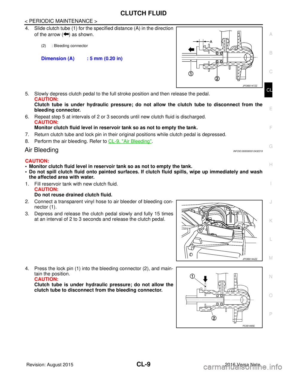
4. Slide clutch tube (1) for the specified distance (A) in the direction of the arrow ( ) as shown.
5. Slowly depress clutch pedal to the full stroke position and then release the pedal. CAUTION:
Clutch tube is under hydraulic pressure; do not allow the clutch tube to disconnect from the
bleeding connector.
6. Repeat step 5 at intervals of 2 or 3 seconds until new clutch fluid is discharged. CAUTION:
Monitor clutch fluid level in reservoir tank so as not to empty the tank.
7. Return clutch tube and lock pin in their original positions while clutch pedal is depressed.
8. Perform the air bleeding. Refer to CL-9, "
Air Bleeding".
Air BleedingINFOID:0000000012432219
CAUTION:
• Monitor clutch fluid level in reservoir tank so as not to empty the tank.
• Do not spill clutch fluid onto painted surfaces. If clutch fluid spil ls, wipe up immediately and wash
the affected area with water.
1. Fill reservoir tank with new clutch fluid. CAUTION:
Do not reuse drained clutch fluid.
2. Connect a transparent vinyl hose to air bleeder of bleeding con- nector (1).
3. Depress and release the clutch pedal slowly and fully 15 times at an interval of 2 to 3 seconds and release the clutch pedal.
4. Press the lock pin (1) into the bleeding connector (2), and main- tain the position.
CAUTION:
Clutch tube is under hydraulic pressure; do not allow the
clutch tube to disconnect from the bleeding connector.
(2) : Bleeding connector
Dimension (A) : 5 mm (0.20 in)
JPDIB0147ZZ
JPDIB0144ZZ
PCIB1495E
Revision: August 2015 2016 Versa Note
cardiagn.com
Page 636 of 3641
CL-10
< PERIODIC MAINTENANCE >
CLUTCH FLUID
5. Slide clutch tube (1) for the specified distance (A) in the directionof the arrow ( ) as shown and immediately depress the clutch
pedal and hold it, to bleed the air from the system.
CAUTION:
Clutch tube is under hydraulic pressure; do not allow the
clutch tube to disconnect from the bleeding connector.
6. Return clutch tube and lock pin in their original positions.
7. Release clutch pedal and wait for 5 seconds.
8. Repeat steps 3 to 7 until no bubbles are observed in the clutch fluid.
9. Check that the clutch fluid level in the reservoir tank is within the specified range after air bleeding. Refer to CL-7, "
Inspection".
(2) : Bleeding connector
Dimension (A) : 5 mm (0.20 in)
JPDIB0147ZZ
Revision: August 2015 2016 Versa Note
cardiagn.com
Page 637 of 3641
CLUTCH PEDALCL-11
< REMOVAL AND INSTALLATION >
CEF
G H
I
J
K L
M A
B
CL
N
O P
REMOVAL AND INSTALLATION
CLUTCH PEDAL
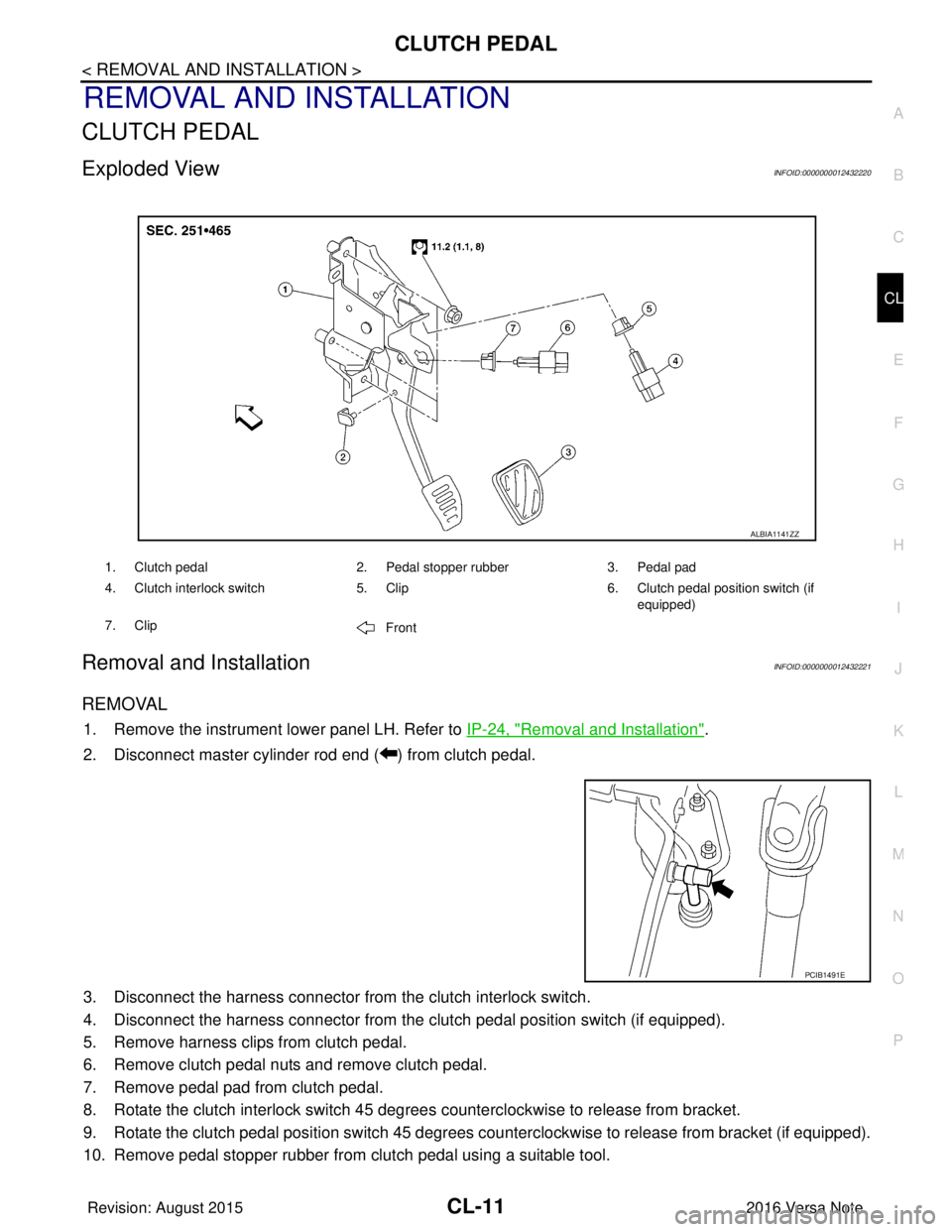
Exploded ViewINFOID:0000000012432220
Removal and InstallationINFOID:0000000012432221
REMOVAL
1. Remove the instrument lower panel LH. Refer to IP-24, "Removal and Installation".
2. Disconnect master cylinder rod end ( ) from clutch pedal.
3. Disconnect the harness connector from the clutch interlock switch.
4. Disconnect the harness connector from the clutch pedal position switch (if equipped).
5. Remove harness clips from clutch pedal.
6. Remove clutch pedal nuts and remove clutch pedal.
7. Remove pedal pad from clutch pedal.
8. Rotate the clutch interlock switch 45 degrees counterclockwise to release from bracket.
9. Rotate the clutch pedal position switch 45 degrees c ounterclockwise to release from bracket (if equipped).
10. Remove pedal stopper rubber from clutch pedal using a suitable tool.
1. Clutch pedal 2. Pedal stopper rubber3. Pedal pad
4. Clutch interlock switch 5. Clip6. Clutch pedal position switch (if
equipped)
7. Clip Front
ALBIA1141ZZ
PCIB1491E
Revision: August 2015 2016 Versa Note
cardiagn.com