Page 638 of 3641
CL-12
< REMOVAL AND INSTALLATION >
CLUTCH PEDAL
INSTALLATION
Installation is in the reverse order of removal.
CAUTION:
Press master cylinder rod end into clutch pedal until it stops.
Inspection and AdjustmentINFOID:0000000012432222
INSPECTION AFTER REMOVAL
• Check clutch pedal for bend, damage, or a cracked weld. If bend, damage, or a cracked weld is found,
replace clutch pedal.
• Check pedal stopper rubber. If damage or deforma tion is found, replace pedal stopper rubber.
• Check pedal pad. If wear or damage is found, replace pedal pad.
INSPECTION AND ADJUSTMENT AFTER INSTALLATION
• Inspect the clutch interlock switch pos ition and adjust as necessary. Refer to CL-5, "Inspection and Adjust-
ment".
• Inspect the clutch pedal position switch position and adjust as necessary (if equipped). Refer to CL-5,
"Inspection and Adjustment".
Revision: August 20152016 Versa Note
cardiagn.com
Page 639 of 3641
CLUTCH MASTER CYLINDERCL-13
< REMOVAL AND INSTALLATION >
CEF
G H
I
J
K L
M A
B
CL
N
O P
CLUTCH MASTER CYLINDER
Exploded ViewINFOID:0000000012432223
Removal and InstallationINFOID:0000000012432224
CAUTION:
• Do not spill clutch fluid onto pa inted surfaces. If clutch fluid spills, wipe up immediately and wash
the affected area with water.
• Do not disassemble clut ch master cylinder.
NOTE:
When removing components such as hoses, tubes/lines, etc. , cap or plug openings to prevent fluid from spill-
ing.
REMOVAL
1. Remove battery. Refer to PG-70, "Removal and Installation (Battery)".
2. Remove air cleaner and air duct. Refer to EM-26, "
Removal and Installation".
3. Remove IPDM E/R. Refer to PCS-30, "
Removal and Installation".
4. Remove ECM bracket nuts (A). : Front
1. Reservoir hose 2. Master cylinder
JPDIB0222ZZ
JPDIB0233ZZ
Revision: August 2015 2016 Versa Note
cardiagn.com
Page 640 of 3641

CL-14
< REMOVAL AND INSTALLATION >
CLUTCH MASTER CYLINDER
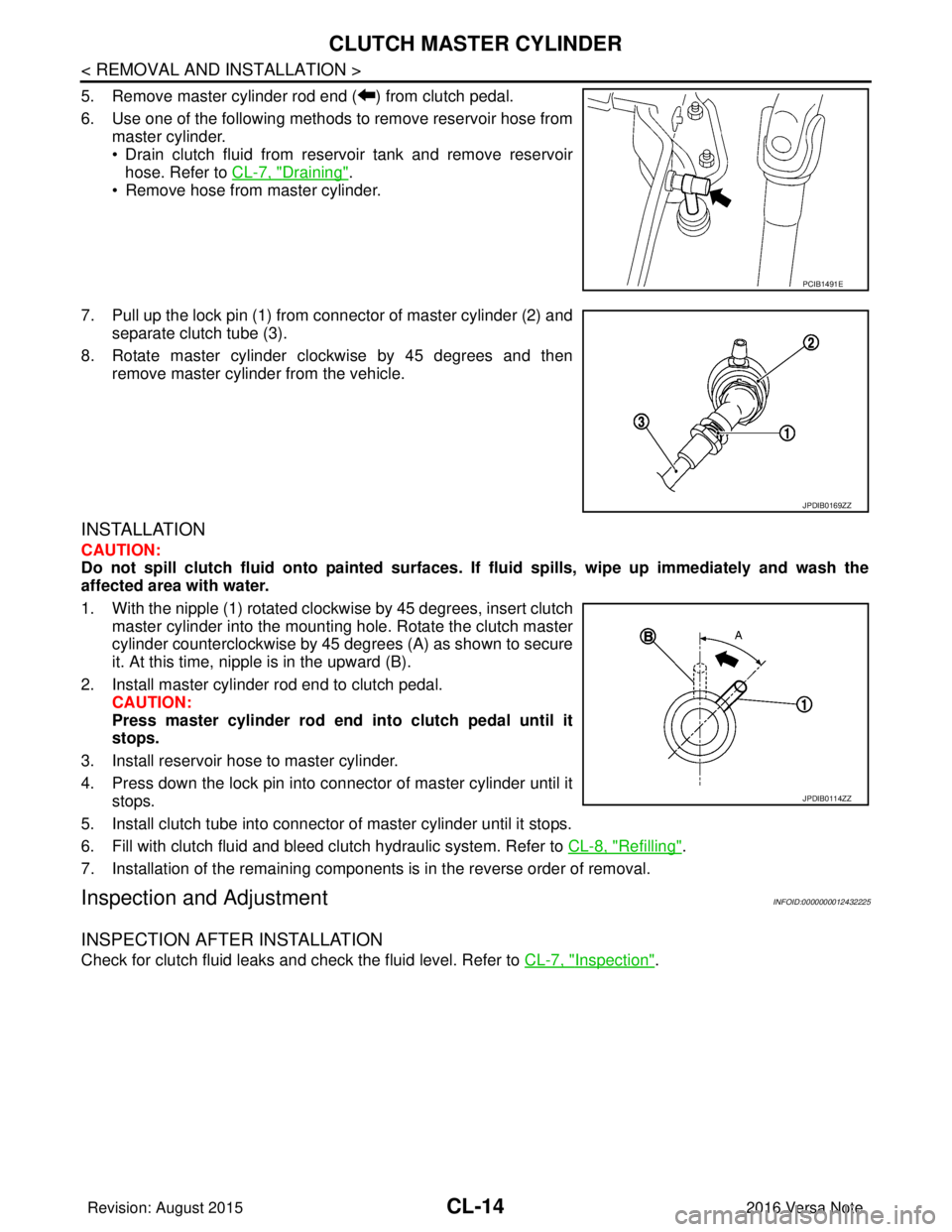
5. Remove master cylinder rod end ( ) from clutch pedal.
6. Use one of the following methods to remove reservoir hose frommaster cylinder.
• Drain clutch fluid from reservoir tank and remove reservoirhose. Refer to CL-7, "
Draining".
• Remove hose from master cylinder.
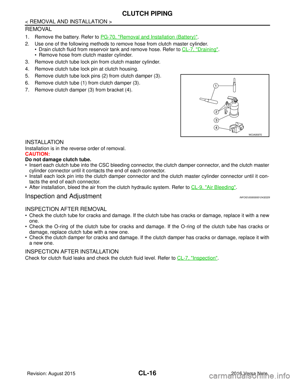
7. Pull up the lock pin (1) from connector of master cylinder (2) and separate clutch tube (3).
8. Rotate master cylinder clockwise by 45 degrees and then remove master cylinder from the vehicle.
INSTALLATION
CAUTION:
Do not spill clutch fluid onto pa inted surfaces. If fluid spills, wipe up imme diately and wash the
affected area with water.
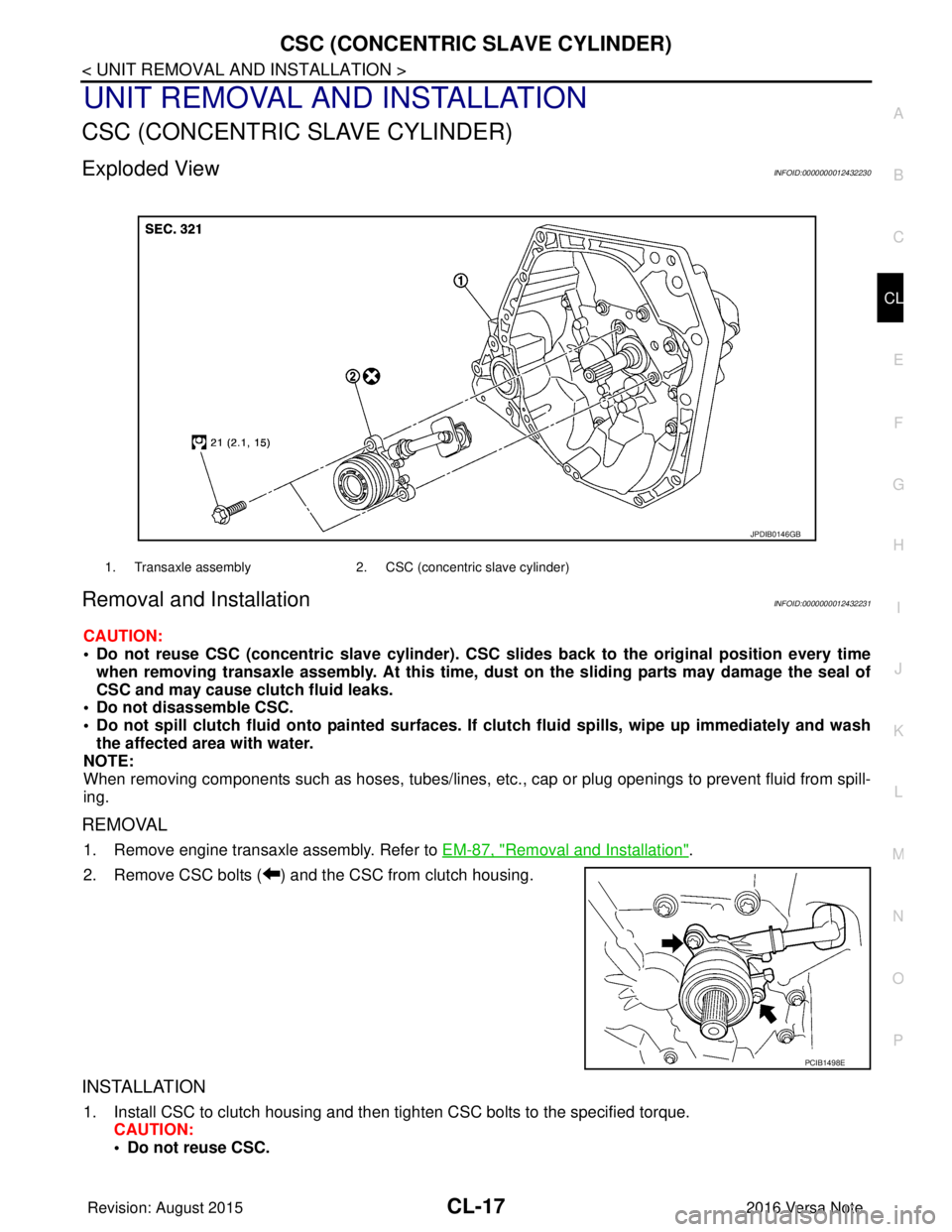
1. With the nipple (1) rotated clockwise by 45 degrees, insert clutch master cylinder into the mounting hole. Rotate the clutch master
cylinder counterclockwise by 45 degrees (A) as shown to secure
it. At this time, nipple is in the upward (B).
2. Install master cylinder rod end to clutch pedal. CAUTION:
Press master cylinder rod end into clutch pedal until it
stops.
3. Install reservoir hose to master cylinder.
4. Press down the lock pin into connector of master cylinder until it stops.
5. Install clutch tube into connector of master cylinder until it stops.
6. Fill with clutch fluid and bleed clutch hydraulic system. Refer to CL-8, "
Refilling".
7. Installation of the remaining components is in the reverse order of removal.
Inspection and AdjustmentINFOID:0000000012432225
INSPECTION AFTER INSTALLATION
Check for clutch fluid leaks and check the fluid level. Refer to CL-7, "Inspection".
PCIB1491E
JPDIB0169ZZ
JPDIB0114ZZ
Revision: August 2015 2016 Versa Note
cardiagn.com
Page 641 of 3641
CLUTCH PIPINGCL-15
< REMOVAL AND INSTALLATION >
CEF
G H
I
J
K L
M A
B
CL
N
O P
CLUTCH PIPING
Exploded ViewINFOID:0000000012432226
Hydraulic LayoutINFOID:0000000012432227
Removal and InstallationINFOID:0000000012432228
CAUTION:
Do not spill clutch fluid onto painted surfaces. If clutch fluid spills, wipe up immediately and wash the
affected area with water.
NOTE:
When removing components such as hoses, tubes/lines, etc. , cap or plug openings to prevent fluid from spill-
ing.
1. CSC (Concentric Slave Cylinder) 2. Clip 3. Clutch tube
4. Clutch damper 5. Bracket6. Master cylinder
AWDIA1109ZZ
1. Clutch tube 2. Lock pin3. CSC (concentric slave cylinder)
4. Clutch damper 5. Master cylinder6. Clutch pedal
PCIB1499E
Revision: August 2015 2016 Versa Note
cardiagn.com
Page 642 of 3641

CL-16
< REMOVAL AND INSTALLATION >
CLUTCH PIPING
REMOVAL
1. Remove the battery. Refer to PG-70, "Removal and Installation (Battery)".
2. Use one of the following methods to remove hose from clutch master cylinder. • Drain clutch fluid from reservoir tank and remove hose. Refer to CL-7, "
Draining".
• Remove hose from clutch master cylinder.
3. Remove clutch tube lock pin from clutch master cylinder.
4. Remove clutch tube lock pin at clutch housing.
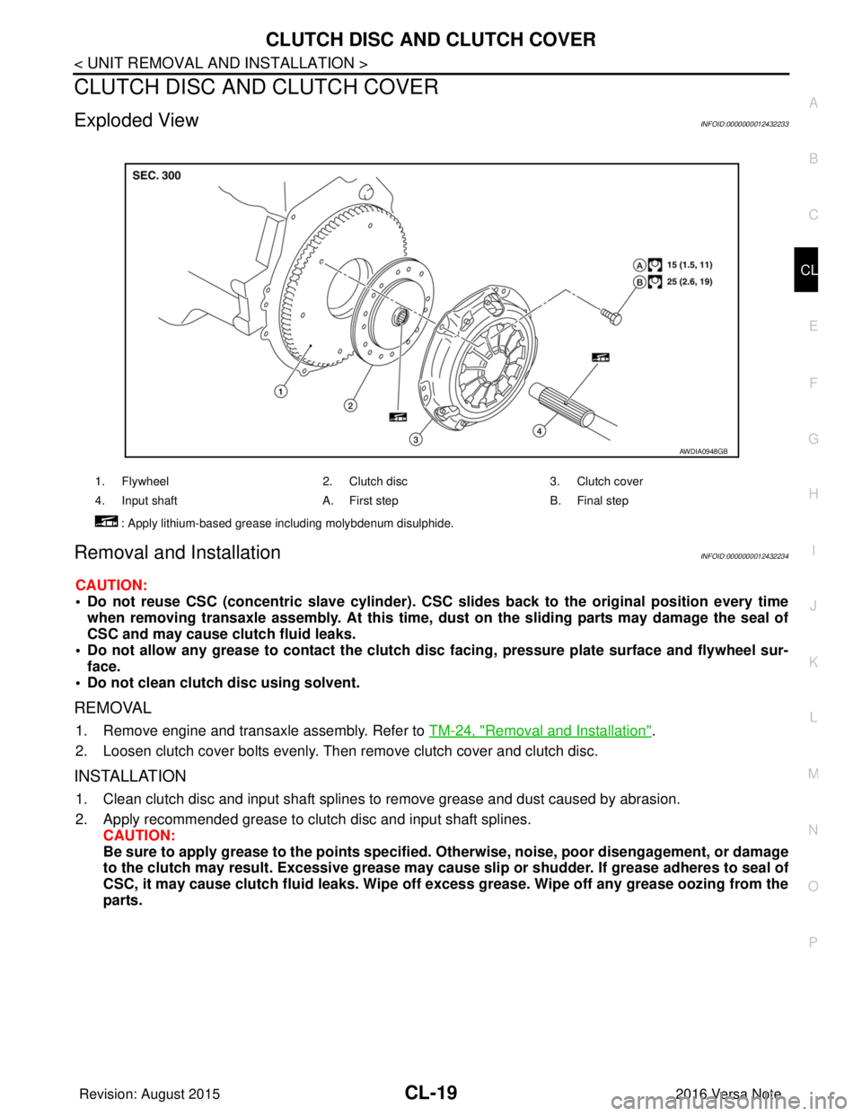
5. Remove clutch tube lock pins (2) from clutch damper (3).
6. Remove clutch tube (1) from clutch damper (3).
7. Remove clutch damper (3) from bracket (4).
INSTALLATION
Installation is in the reverse order of removal.
CAUTION:
Do not damage clutch tube.
• Insert each clutch tube into the CSC bleeding connector, the clutch damper connector, and the clutch master cylinder connector until it contacts the end of each connector.
• Install each lock pin into the clutch damper connecto r and the clutch master cylinder connector until it con-
tacts the end of each connector.
• After installation, bleed the air from the clutch hydraulic system. Refer to CL-9, "
Air Bleeding".
Inspection and AdjustmentINFOID:0000000012432229
INSPECTION AFTER REMOVAL
• Check the clutch tube for cracks and damage. If the cl utch tube has cracks or damage, replace it with a new
one.
• Check the O-ring of the clutch tube for cracks and dam age. If the O-ring of the clutch tube has cracks or
damage, replace clutch tube with a new one.
• Check the clutch damper for cracks and damage. If the clutch damper has cracks or damage, replace it with
a new one.
INSPECTION AFTER INSTALLATION
Check for clutch fluid leaks and check the clutch fluid level. Refer to CL-7, "Inspection".
WCIA0597E
Revision: August 2015 2016 Versa Note
cardiagn.com
Page 643 of 3641

CSC (CONCENTRIC SLAVE CYLINDER)CL-17
< UNIT REMOVAL AND INSTALLATION >
CEF
G H
I
J
K L
M A
B
CL
N
O P
UNIT REMOVAL AND INSTALLATION
CSC (CONCENTRIC SLAVE CYLINDER)
Exploded ViewINFOID:0000000012432230
Removal and InstallationINFOID:0000000012432231
CAUTION:
• Do not reuse CSC (concentric slave cylinder). CSC slides back to the original position every time
when removing transaxle assembly. At this time, du st on the sliding parts may damage the seal of
CSC and may cause clutch fluid leaks.
• Do not disassemble CSC.
• Do not spill clutch fluid onto pa inted surfaces. If clutch fluid spills, wipe up immediately and wash
the affected area with water.
NOTE:
When removing components such as hoses, tubes/lines, etc. , cap or plug openings to prevent fluid from spill-
ing.
REMOVAL
1. Remove engine transaxle assembly. Refer to EM-87, "Removal and Installation".
2. Remove CSC bolts ( ) and the CSC from clutch housing.
INSTALLATION
1. Install CSC to clutch housing and then tighten CSC bolts to the specified torque. CAUTION:
• Do not reuse CSC.
1. Transaxle assembly 2. CSC (concentric slave cylinder)
JPDIB0146GB
PCIB1498E
Revision: August 2015 2016 Versa Note
cardiagn.com
Page 644 of 3641
CL-18
< UNIT REMOVAL AND INSTALLATION >
CSC (CONCENTRIC SLAVE CYLINDER)
• Do not insert and operate CSC when transaxle is removed. Piston and stopper of CSC compo-nents may fall off.
2. Install engine and transaxle assembly. Refer to EM-87, "
Removal and Installation".
Inspection and AdjustmentINFOID:0000000012432232
INSPECTION AFTER INSTALLATION
Check for clutch fluid leaks and clutch fluid level. Refer to CL-7, "Inspection".
ADJUSTMENT AFTER INSTALLATION
Perform the air bleeding. Refer to CL-9, "Air Bleeding".
Revision: August 2015 2016 Versa Note
cardiagn.com
Page 645 of 3641

CLUTCH DISC AND CLUTCH COVERCL-19
< UNIT REMOVAL AND INSTALLATION >
CEF
G H
I
J
K L
M A
B
CL
N
O P
CLUTCH DISC AND CLUTCH COVER
Exploded ViewINFOID:0000000012432233
Removal and InstallationINFOID:0000000012432234
CAUTION:
• Do not reuse CSC (concentric slave cylinder). CSC slides back to the original position every time
when removing transaxle assembly. At this time, du st on the sliding parts may damage the seal of
CSC and may cause clutch fluid leaks.
• Do not allow any grease to contact the clutch di sc facing, pressure plate surface and flywheel sur-
face.
• Do not clean clutch disc using solvent.
REMOVAL
1. Remove engine and transaxle assembly. Refer to TM-24, "Removal and Installation".
2. Loosen clutch cover bolts evenly. Then remove clutch cover and clutch disc.
INSTALLATION
1. Clean clutch disc and input shaft splines to remove grease and dust caused by abrasion.
2. Apply recommended grease to clutch disc and input shaft splines. CAUTION:
Be sure to apply grease to the points specified. Otherwise, noise, poor disengagement, or damage
to the clutch may result. Excessi ve grease may cause slip or shudder. If grease adheres to seal of
CSC, it may cause clutch fluid leaks. Wipe off excess grease. Wipe off any grease oozing from the
parts.
1. Flywheel 2. Clutch disc3. Clutch cover
4. Input shaft A. First stepB. Final step
: Apply lithium-based grease including molybdenum disulphide.
AWDIA0948GB
Revision: August 2015 2016 Versa Note
cardiagn.com