Page 623 of 3641
CHG-28
< SYMPTOM DIAGNOSIS >
CHARGING SYSTEM
SYMPTOM DIAGNOSIS
CHARGING SYSTEM
Symptom TableINFOID:0000000012431259
SymptomReference
Battery discharged
Refer to CHG-14, "
Work Flow (With EXP-800 NI or GR8-1200 NI)"
or CHG-17, "
Work Flow (Without EXP-800 NI or GR8-1200 NI)".
The charge warning lamp does not illuminate when the ignition
switch is set to ON.
The charge warning lamp does not turn OFF after the engine
starts.
The charging warning lamp turns ON when increasing the engine
speed.
Revision: August 2015
2016 Versa Note
cardiagn.com
Page 628 of 3641

CL-2
< PRECAUTION >
PRECAUTIONS
PRECAUTION
PRECAUTIONS
Precaution for Supplemental Restraint System (SRS) "AIR BAG" and "SEAT BELT
PRE-TENSIONER"
INFOID:0000000012432210
The Supplemental Restraint System such as “A IR BAG” and “SEAT BELT PRE-TENSIONER”, used along
with a front seat belt, helps to reduce the risk or severity of injury to the driver and front passenger for certain
types of collision. Information necessary to service the system safely is included in the SR and SB section of
this Service Manual.
WARNING:
• To avoid rendering the SRS inopera tive, which could increase the risk of personal injury or death in
the event of a collision which would result in air bag inflation, all maintenance must be performed by
an authorized NISSAN/INFINITI dealer.
• Improper maintenance, including in correct removal and installation of the SRS, can lead to personal
injury caused by unintent ional activation of the system. For re moval of Spiral Cable and Air Bag
Module, see the SR section.
• Do not use electrical test equipmen t on any circuit related to the SRS unless instructed to in this
Service Manual. SRS wiring harn esses can be identified by yellow and/or orange harnesses or har-
ness connectors.
PRECAUTIONS WHEN USING POWER TOOLS (AIR OR ELECTRIC) AND HAMMERS
WARNING:
• When working near the Airbag Diagnosis Sensor Unit or other Airbag System sensors with the Igni-
tion ON or engine running, DO NOT use air or electri c power tools or strike near the sensor(s) with a
hammer. Heavy vibration could activate the sensor( s) and deploy the air bag(s), possibly causing
serious injury.
• When using air or electric power tools or hammers , always switch the Ignition OFF, disconnect the
battery and wait at least three minutes before performing any service.
General PrecautionsINFOID:0000000012432211
WARNING:
After cleaning clutch disc, wipe it with a dust collector. Do not use compressed air.
CAUTION:
• Always use recommended clutch fluid. Refer to MA-11, "
Fluids and Lubricants".
• Do not reuse drained clutch fluid.
• Keep painted surface on the body and other parts free of clutch fluid. If fluid spills, wipe up immedi-
ately and wash the affected area with water.
• Do not use mineral oils, such as gasoline or kerosen e. It will ruin the rubber parts of the hydraulic
system.
• Do not reuse CSC (Concentric Slave Cylinder). CS C slides back to the original position every time
when removing transaxle assembly. At this time, dust on the sliding parts may damage the seal of
CSC and may cause clutch fluid leakage. Refer to CL-17, "
Removal and Installation".
• Do not disassemble clutch master cylinder and CSC.
Revision: August 2015 2016 Versa Note
cardiagn.com
Page 630 of 3641
CL-4
< SYMPTOM DIAGNOSIS >
NOISE, VIBRATION AND HARSHNESS (NVH) TROUBLESHOOTING
SYMPTOM DIAGNOSIS
NOISE, VIBRATION AND HARSHNESS (NVH) TROUBLESHOOTING
NVH Troubleshooting ChartINFOID:0000000012432214
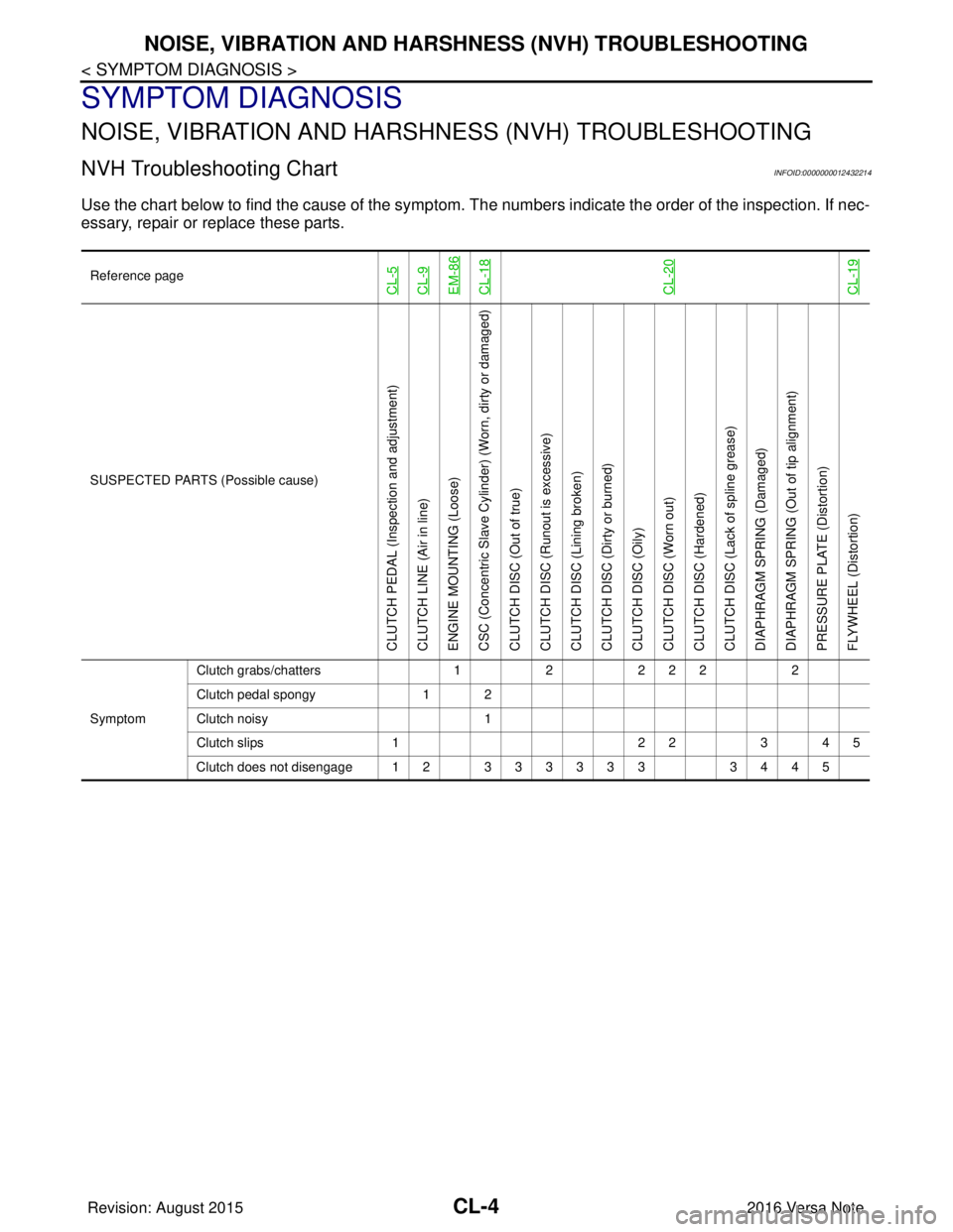
Use the chart below to find the cause of the symptom. T he numbers indicate the order of the inspection. If nec-
essary, repair or replace these parts.
Reference pageCL-5CL-9EM-86CL-18CL-20CL-19
SUSPECTED PARTS (Possible cause)
CLUTCH PEDAL (Inspection and adjustment)
CLUTCH LINE (Air in line)
ENGINE MOUNTING (Loose)
CSC (Concentric Slave Cylinder) (Worn, dirty or damaged)
CLUTCH DISC (Out of true)
CLUTCH DISC (Ru nout is excessive)
CLUTCH DISC (Lining broken)
CLUTCH DISC (Dirty or burned)
CLUTCH DISC (Oily)
CLUTCH DISC (Worn out)
CLUTCH DISC (Hardened)
CLUTCH DISC (Lack of spline grease)
DIAPHRAGM SPRING (Damaged)
DIAPHRAGM SPRING (Out of tip alignment)
PRESSURE PLATE (Distortion)
FLYWHEEL (Distortion)
Symptom Clutch grabs/chatters
122 2 2 2
Clutch pedal spongy 1 2
Clutch noisy 1
Clutch slips 1 2 23 4 5
Clutch does not disengage 12 333333 3445
Revision: August 2015 2016 Versa Note
cardiagn.com
Page 631 of 3641
CLUTCH PEDALCL-5
< PERIODIC MAINTENANCE >
CEF
G H
I
J
K L
M A
B
CL
N
O P
PERIODIC MAINTENANCE
CLUTCH PEDAL
Inspection and AdjustmentINFOID:0000000012432215
INSPECTION
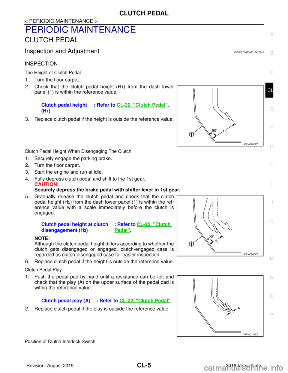
The Height of Clutch Pedal
1. Turn the floor carpet.
2. Check that the clutch pedal height (H
1) from the dash lower
panel (1) is within the reference value.
3. Replace clutch pedal if the height is outside the reference value.
Clutch Pedal Height When Disengaging The Clutch
1. Securely engage the parking brake.
2. Turn the floor carpet.
3. Start the engine and run at idle.
4. Fully depress clutch pedal and shift to the 1st gear. CAUTION:
Securely depress the brake pedal with shifter lever in 1st gear.
5. Gradually release the clutch pedal and check that the clutch pedal height (H
2) from the dash lower panel (1) is within the ref-
erence value with a scale immediately before the clutch is
engaged.
NOTE:
Although the clutch pedal height differs according to whether the
clutch gets disengaged or engaged, clutch-engaged case is
regarded as clutch-disengaged case for easier inspection.
6. Replace clutch pedal if the height is outside the reference value.
Clutch Pedal Play
1. Push the pedal pad by hand until a resistance can be felt and check that the play (A) on the upper surface of the pedal pad is
within the reference value.
2. Replace clutch pedal if the play is outside the reference value.
Position of Clutch Interlock Switch
Clutch pedal height
(H
1) : Refer to
CL-22, "
Clutch Pedal".
JPFIA0065ZZ
Clutch pedal height at clutch
disengagement (H
2) : Refer to CL-22, "
Clutch
Pedal".
JPFIA0068ZZ
Clutch pedal play (A) : Refer to
CL-22, "Clutch Pedal".
JPFIA0121ZZ
Revision: August 2015 2016 Versa Note
cardiagn.com
Page 633 of 3641
CLUTCH FLUIDCL-7
< PERIODIC MAINTENANCE >
CEF
G H
I
J
K L
M A
B
CL
N
O P
CLUTCH FLUID
InspectionINFOID:0000000012432216
CLUTCH FLUID LEAKS
• Check clutch line for cracks, deterioration or other damage. Replace any damaged parts.
• Check for clutch fluid leaks by fully depressing clutch pedal while engine is running. CAUTION:
If leaks occur around connections, reinstall th e lines or replace damaged parts, if necessary.
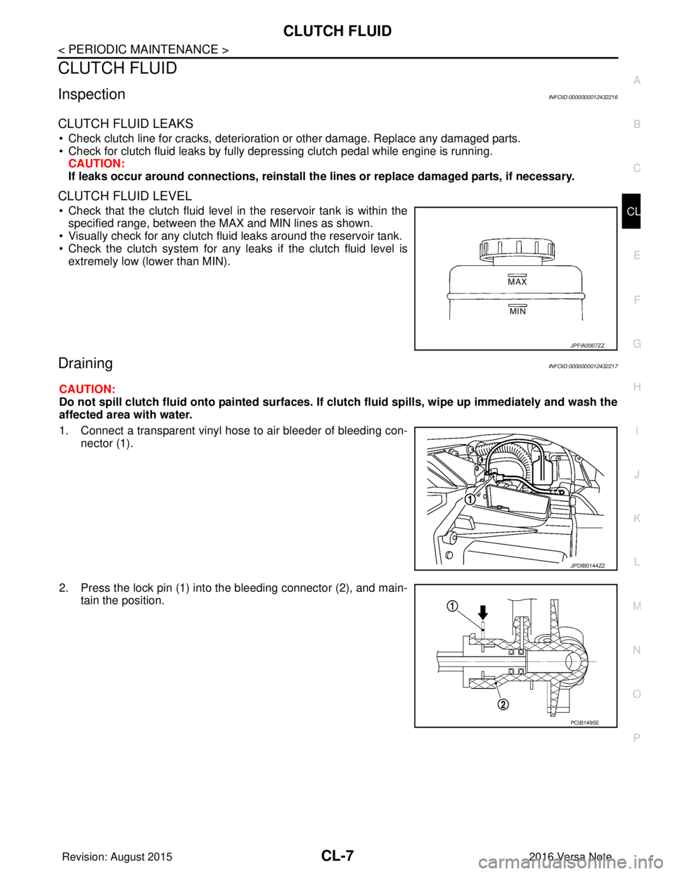
CLUTCH FLUID LEVEL
• Check that the clutch fluid level in the reservoir tank is within the
specified range, between the MAX and MIN lines as shown.
• Visually check for any clutch fluid leaks around the reservoir tank.
• Check the clutch system for any leaks if the clutch fluid level is
extremely low (lower than MIN).
DrainingINFOID:0000000012432217
CAUTION:
Do not spill clutch fluid onto painted surfaces. If clutch fluid spills, wipe up immediately and wash the
affected area with water.
1. Connect a transparent vinyl hose to air bleeder of bleeding con-
nector (1).
2. Press the lock pin (1) into the bleeding connector (2), and main- tain the position.
JPFIA0007ZZ
JPDIB0144ZZ
PCIB1495E
Revision: August 2015 2016 Versa Note
cardiagn.com
Page 643 of 3641
CSC (CONCENTRIC SLAVE CYLINDER)CL-17
< UNIT REMOVAL AND INSTALLATION >
CEF
G H
I
J
K L
M A
B
CL
N
O P
UNIT REMOVAL AND INSTALLATION
CSC (CONCENTRIC SLAVE CYLINDER)
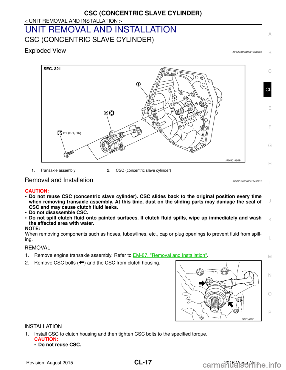
Exploded ViewINFOID:0000000012432230
Removal and InstallationINFOID:0000000012432231
CAUTION:
• Do not reuse CSC (concentric slave cylinder). CSC slides back to the original position every time
when removing transaxle assembly. At this time, du st on the sliding parts may damage the seal of
CSC and may cause clutch fluid leaks.
• Do not disassemble CSC.
• Do not spill clutch fluid onto pa inted surfaces. If clutch fluid spills, wipe up immediately and wash
the affected area with water.
NOTE:
When removing components such as hoses, tubes/lines, etc. , cap or plug openings to prevent fluid from spill-
ing.
REMOVAL
1. Remove engine transaxle assembly. Refer to EM-87, "Removal and Installation".
2. Remove CSC bolts ( ) and the CSC from clutch housing.
INSTALLATION
1. Install CSC to clutch housing and then tighten CSC bolts to the specified torque. CAUTION:
• Do not reuse CSC.
1. Transaxle assembly 2. CSC (concentric slave cylinder)
JPDIB0146GB
PCIB1498E
Revision: August 2015 2016 Versa Note
cardiagn.com
Page 644 of 3641
CL-18
< UNIT REMOVAL AND INSTALLATION >
CSC (CONCENTRIC SLAVE CYLINDER)
• Do not insert and operate CSC when transaxle is removed. Piston and stopper of CSC compo-nents may fall off.
2. Install engine and transaxle assembly. Refer to EM-87, "
Removal and Installation".
Inspection and AdjustmentINFOID:0000000012432232
INSPECTION AFTER INSTALLATION
Check for clutch fluid leaks and clutch fluid level. Refer to CL-7, "Inspection".
ADJUSTMENT AFTER INSTALLATION
Perform the air bleeding. Refer to CL-9, "Air Bleeding".
Revision: August 2015 2016 Versa Note
cardiagn.com
Page 645 of 3641
CLUTCH DISC AND CLUTCH COVERCL-19
< UNIT REMOVAL AND INSTALLATION >
CEF
G H
I
J
K L
M A
B
CL
N
O P
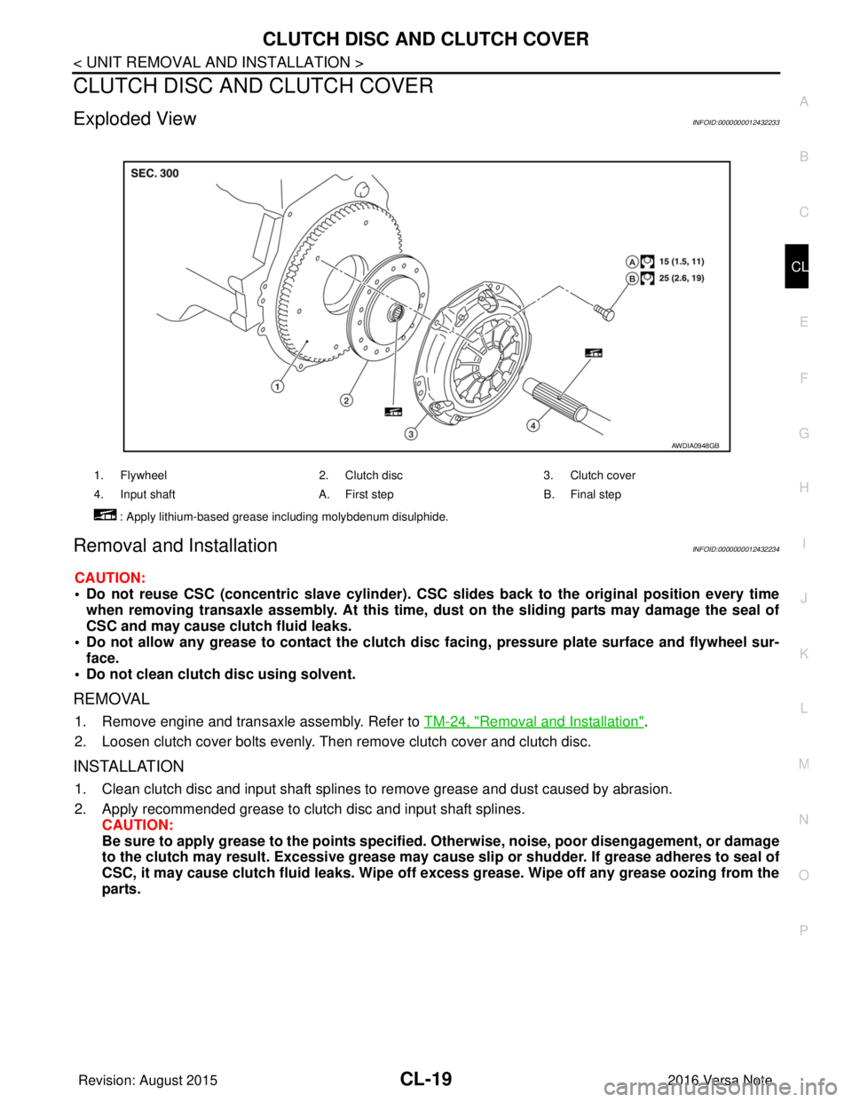
CLUTCH DISC AND CLUTCH COVER
Exploded ViewINFOID:0000000012432233
Removal and InstallationINFOID:0000000012432234
CAUTION:
• Do not reuse CSC (concentric slave cylinder). CSC slides back to the original position every time
when removing transaxle assembly. At this time, du st on the sliding parts may damage the seal of
CSC and may cause clutch fluid leaks.
• Do not allow any grease to contact the clutch di sc facing, pressure plate surface and flywheel sur-
face.
• Do not clean clutch disc using solvent.
REMOVAL
1. Remove engine and transaxle assembly. Refer to TM-24, "Removal and Installation".
2. Loosen clutch cover bolts evenly. Then remove clutch cover and clutch disc.
INSTALLATION
1. Clean clutch disc and input shaft splines to remove grease and dust caused by abrasion.
2. Apply recommended grease to clutch disc and input shaft splines. CAUTION:
Be sure to apply grease to the points specified. Otherwise, noise, poor disengagement, or damage
to the clutch may result. Excessi ve grease may cause slip or shudder. If grease adheres to seal of
CSC, it may cause clutch fluid leaks. Wipe off excess grease. Wipe off any grease oozing from the
parts.
1. Flywheel 2. Clutch disc3. Clutch cover
4. Input shaft A. First stepB. Final step
: Apply lithium-based grease including molybdenum disulphide.
AWDIA0948GB
Revision: August 2015 2016 Versa Note
cardiagn.com