2016 NISSAN NOTE engine coolant
[x] Cancel search: engine coolantPage 1749 of 3641
HEADLAMP AIMING ADJUSTMENTEXL-97
< PERIODIC MAINTENANCE >
C
DE
F
G H
I
J
K
M A
B
EXL
N
O P
PERIODIC MAINTENANCE
HEADLAMP AIMING ADJUSTMENT
InspectionINFOID:0000000012432828
PREPARATION BEFORE ADJUSTING
Before performing aiming adjustment, check the following:
• Ensure all tires are inflated to correct pressure.
• Place vehicle and screen on level surface.
• Ensure there is no load in vehicle other than the driver (or equivalent weight placed in driver's position).
• Coolant and engine oil filled to correct level, and fuel tank full.
• Remove cargo and/or luggage to maintain an unloaded vehicle condition.
• Confirm spare tire, jack and tools are properly stowed.
• Carefully wipe off any dirt from headlamp lens. CAUTION:
Do not use organic solvent (thinner, gasoline etc.)
• Place a driver or equivalent weight of 68.5 kg (150 lb) on the driver seat.
• By hand, bounce the front and rear of the vehicle to settle the suspension and eliminate any static load.
• Place the front tires in the straight ahead position.
• Confirm headlamp aiming switch is set to "0" (zero) position.
• Aim each headlamp individually and ensure other headlamp beam pattern is blocked from screen.
NOTE:
• For headlamp aiming details, refer to regulations in your area.
• By regulation, no means for horizontal aim adjustment is provided from the factory; only vertical aim is
adjustable.
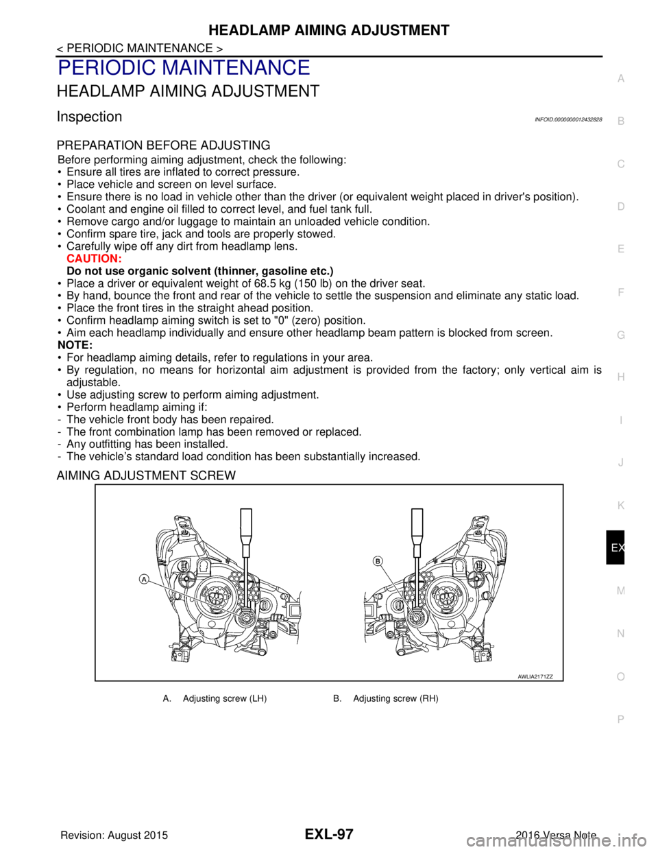
• Use adjusting screw to perform aiming adjustment.
• Perform headlamp aiming if:
- The vehicle front body has been repaired.
- The front combination lamp has been removed or replaced.
- Any outfitting has been installed.
- The vehicle’s standard load condition has been substantially increased.
AIMING ADJUSTMENT SCREW
AWLIA2171ZZ
A. Adjusting screw (LH) B. Adjusting screw (RH)
Revision: August 2015 2016 Versa Note
cardiagn.com
Page 1752 of 3641
EXL-100
< PERIODIC MAINTENANCE >
FRONT FOG LAMP AIMING ADJUSTMENT
FRONT FOG LAMP AIMING ADJUSTMENT
InspectionINFOID:0000000012432830
PREPARATION BEFORE ADJUSTING
Before performing aiming adjustment procedure, check the following:
• Ensure all tires are inflated to correct pressure.
• Place vehicle and screen on level surface.
• Ensure there is no load in vehicle other than the driver (or equivalent weight placed in driver's position).
• Coolant and engine oil filled to correct level, and fuel tank full.
• Remove cargo and/or luggage to maintain an unloaded vehicle condition.
• Confirm spare tire, jack and tools are properly stowed.
• Carefully wipe off any dirt from fog lamp lens. CAUTION:
Do not use organic solvent (thinner, gasoline etc.)
• Place a driver or equivalent weight of 68.5 kg (150 lb) on the driver seat.
• By hand, bounce the front and rear of the vehicle to settle the suspension and eliminate any static load.
• Place the front tires in the straight ahead position.
• Aim each headlamp individually and ensure other headlamp beam pattern is blocked from screen.
NOTE:
• For headlamp aiming details, refer to regulations in your area.
• By regulation, no means for horizontal aim adjustment is provided from the factory; only vertical aim is
adjustable.
• Use adjusting screw to perform aiming adjustment.
• Perform headlamp aiming if:
- The vehicle front body has been repaired.
- The front combination lamp has been removed or replaced.
- Any outfitting has been installed.
- The vehicle’s standard load condition has been substantially increased.
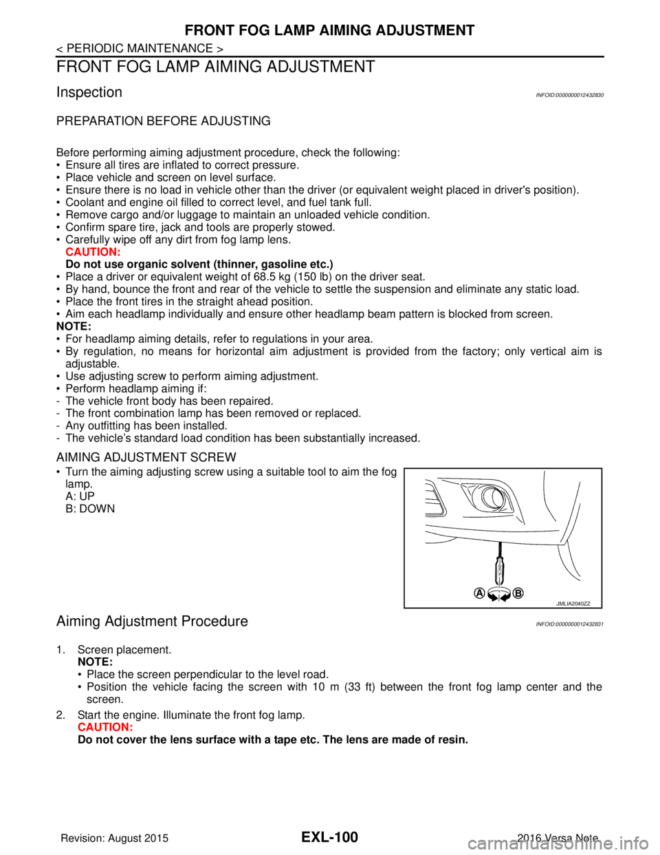
AIMING ADJUSTMENT SCREW
• Turn the aiming adjusting screw using a suitable tool to aim the fog
lamp.
A: UP
B: DOWN
Aiming Adjustment ProcedureINFOID:0000000012432831
1. Screen placement. NOTE:
• Place the screen perpendicular to the level road.
• Position the vehicle facing the screen with 10 m (33 ft) between the front fog lamp center and thescreen.
2. Start the engine. Illuminate the front fog lamp. CAUTION:
Do not cover the lens surface with a tape etc. The lens are made of resin.
JMLIA2040ZZ
Revision: August 2015 2016 Versa Note
cardiagn.com
Page 1779 of 3641

EXT-12
< SYSTEM DESCRIPTION >
SYSTEM
While driving at high speed, ECM operates the shutter to open position when the vehicle reaches the specified
speed in order to prevent the shutte r from shutting up by wind resistance.
When the vehicle speed is reduced below the specified speed ECM operates active grille shutter to open posi-
tion.
ACTIVE GRILLE SHUTTER OPERATIONAL CONDITIONS
ECM operates active grille shutter to close position when following a ll conditions are met.
ECM operates active grille shutter to open positi on when one of the following conditions is met.
Item Status
Active grille shutter initial position learning Complete
Vehicle speed Approx. 30 - 140 km/h (19 - 88 MPH)
Engine coolant temperature Approx. less than 95°C (203 °F)
Engine oil temperature Approx. less than 140°C (284 °F)
CVT fluid temperature Approx. less than 135°C (275 °F)
Cooling fan OFF
Refrigerant pressure 0.78 MPa (7.95 kg/cm
2, 113.1 psi) or less
Malfunction of engine coolant temperature sensor system Not detected
Malfunction of engine oil temperature sensor system Not detected
Malfunction of vehicle speed sensor system Not detected
Malfunction of CAN communication system Not detected
ItemStatus
Vehicle speed • 22 km/h (14 MPH) or less
• 140 km/h (88 MPH) or more
Engine coolant temperature Approx. 95°C (203 °F) or more
Engine oil temperature Approx. 140°C (284 °F) or more
CVT fluid temperature Approx. 135°C (275 °F) or more
Cooling fan ON
Refrigerant pressure 1.18 MPa (12.04 kg/cm
2, 171.1 psi) or more
Malfunction of engine coolant temperature sensor system Detected
Malfunction of engine oil temperature sensor system Detected
Malfunction of vehicle speed sensor system Detected
Malfunction of CAN communication system Detected
Revision: August 2015 2016 Versa Note
cardiagn.com
Page 1847 of 3641
FSU-2
< PRECAUTION >
PRECAUTIONS
PRECAUTION
PRECAUTIONS
Precaution for Supplemental Restraint System (SRS) "AIR BAG" and "SEAT BELT
PRE-TENSIONER"
INFOID:0000000012430294
The Supplemental Restraint System such as “A IR BAG” and “SEAT BELT PRE-TENSIONER”, used along
with a front seat belt, helps to reduce the risk or severity of injury to the driver and front passenger for certain
types of collision. Information necessary to service the system safely is included in the SR and SB section of
this Service Manual.
WARNING:
• To avoid rendering the SRS inopera tive, which could increase the risk of personal injury or death in
the event of a collision which would result in air bag inflation, all maintenance must be performed by
an authorized NISSAN/INFINITI dealer.
• Improper maintenance, including in correct removal and installation of the SRS, can lead to personal
injury caused by unintent ional activation of the system. For re moval of Spiral Cable and Air Bag
Module, see the SR section.
• Do not use electrical test equipmen t on any circuit related to the SRS unless instructed to in this
Service Manual. SRS wiring harn esses can be identified by yellow and/or orange harnesses or har-
ness connectors.
PRECAUTIONS WHEN USING POWER TOOLS (AIR OR ELECTRIC) AND HAMMERS
WARNING:
• When working near the Airbag Diagnosis Sensor Unit or other Airbag System sensors with the Igni-
tion ON or engine running, DO NOT use air or electri c power tools or strike near the sensor(s) with a
hammer. Heavy vibration could activate the sensor( s) and deploy the air bag(s), possibly causing
serious injury.
• When using air or electric power tools or hammers , always switch the Ignition OFF, disconnect the
battery and wait at least three minutes before performing any service.
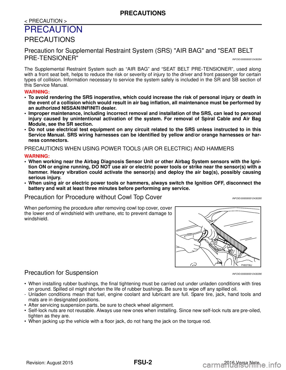
Precaution for Procedure without Cowl Top CoverINFOID:0000000012430295
When performing the procedure after removing cowl top cover, cover
the lower end of windshield with urethane, etc to prevent damage to
windshield.
Precaution for SuspensionINFOID:0000000012430296
• When installing rubber bushings, the final tightening mu st be carried out under unladen conditions with tires
on ground. Spilled oil might shorten the life of rubber bushings. Be sure to wipe off any spilled oil.
- Unladen conditions mean that fuel, engine coolant and lubricant are full. Spare tire, jack, hand tools and mats are in designated positions.
• After servicing suspension parts, be sure to check wheel alignment.
• Self-lock nuts are not reusable. Always use new ones when installing. Since new self-lock nuts are pre-oiled,
tighten as they are.
• When jacking up the vehicle with a floor jack, do not hang the jack on the torque rod.
PIIB3706J
Revision: August 2015 2016 Versa Note
cardiagn.com
Page 1852 of 3641
WHEEL ALIGNMENTFSU-7
< PERIODIC MAINTENANCE >
C
DF
G H
I
J
K L
M A
B
FSU
N
O P
WHEEL ALIGNMENT
InspectionINFOID:0000000012430301
PRELIMINARY INSPECTION
WARNING:
Always adjust the wheel alignment with the vehicle on a flat surface.
NOTE:
If the wheel alignment is out of s pecification, inspect and replace any damaged or worn rear suspension parts
before making any adjustments.
1. Check and adjust the wheel alignment with the vehicle under unladen conditions. “Unladen conditions”
means that the fuel, engine coolant, and lubricants are full; the spare tire, jack, hand tools and mats are in
designated positions.
2. Check the tires for incorrect air pressure and excessive wear.
3. Check the wheels for run out and damage. Refer to WT-54, "
Wheel".
4. Check the wheel bearing axial end play. Refer to FAX-27, "
Wheel Bearing".
5. Check the shock absorbers for leaks or damage.
6. Check each mount point of the suspension co mponents for any excessive looseness or damage.
7. Check each link, arm, and the suspension member for any damage.
8. Check the vehicle height. Refer to FSU-21, "
Wheelarch Height (Unladen*)".
GENERAL INFORMATION AND RECOMMENDATIONS
1. A Four-Wheel Thrust Alignment should be performed.
• This type of alignment is recomm ended for any NISSAN/INFINITI vehicle.
• The four-wheel “thrust” process helps ensure that the vehicle is properly aligned and the steering wheel
is centered.
• The alignment machine itself should be capabl e of accepting any NISSAN/INFINITI vehicle.
• The alignment machine should be checked to ensure that it is level.
2. Make sure the alignment machine is properly calibrated. • Your alignment machine should be regularly calibrated in order to give correct information.
• Check with the manufacturer of your specific a lignment machine for their recommended Service/Cali-
bration Schedule.
ALIGNMENT PROCESS
IMPORTANT: Use only the alignment specifications listed in this Service Manual. Refer to FSU-20, "Wheel
Alignment (Unladen*1)".
• When displaying the alignment settings, many alignment machines use “indicators”: (Green/red, plus or
minus, Go/No Go). Do NOT use these indicators.
- The alignment specifications programmed into your alignment machine that operate these indicators may
not be correct.
- This may result in an ERROR.
• Most camera-type alignment machines are equipped with "Rolling Compensation" method and optional
"Jacking Compensation" method to "compensate" the alignment targets or head units.
"Rolling Compensation" is the preferred method.
- If using the "Rolling Compensation" method, after inst alling the alignment targets or head units, push or pull
on the rear wheel to move the vehicle. Do not push or pull on the vehicle body.
- If using the "Jacking Compensation" method, after inst alling the alignment targets or head units, raise the
vehicle and rotate the wheels 1/2 turn in either direction.
NOTE:
Do not use the "Rolling Compensation" method if you are using sensor-type alignment equipment.
• Follow all instructions for the alignment machine you're using for more information.
CAMBER, CASTER AND KINGPIN INCLINATION ANGLES INSPECTION
• Camber, caster, kingpin inclination angles cannot be adjusted.
• Before inspection, set the front wheels onto a turning radius gauge. Set the rear wheels onto a pad that has
the same height so the vehicle will remain horizontal.
TOTAL TOE-IN INSPECTION
Measure the total toe-in using the following procedure.
Revision: August 2015 2016 Versa Note
cardiagn.com
Page 1865 of 3641
FSU-20
< SERVICE DATA AND SPECIFICATIONS (SDS)
SERVICE DATA AND SPECIFICATIONS (SDS)
SERVICE DATA AND SPECIFICATIONS (SDS)
SERVICE DATA AND SPECIFICATIONS (SDS)
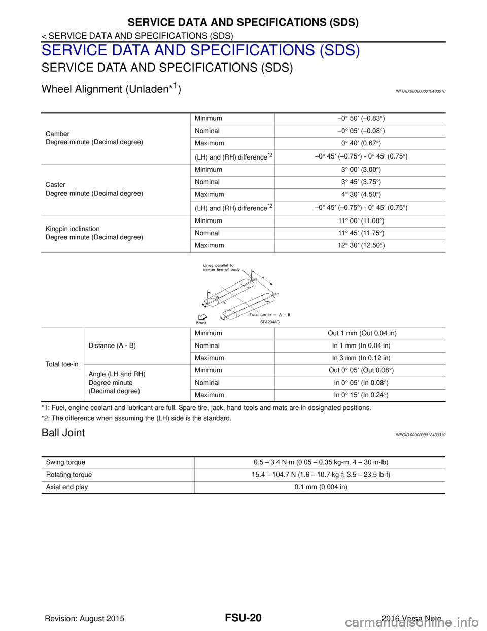
Wheel Alignment (Unladen*1)INFOID:0000000012430318
*1: Fuel, engine coolant and lubricant are full. Spare tire, jack, hand tools and mats are in designated positions.
*2: The difference when assuming the (LH) side is the standard.
Ball JointINFOID:0000000012430319
Camber
Degree minute (Decimal degree)Minimum
−0 ° 50 ′ ( −0.83 °)
Nominal −0 ° 05 ′ ( −0.08 °)
Maximum 0° 40 ′ (0.67 °)
(LH) and (RH) difference
*2–0 ° 45 ′ (–0.75 °) - 0 ° 45 ′ (0.75 °)
Caster
Degree minute (Decimal degree) Minimum
3° 00 ′ (3.00 °)
Nominal 3° 45 ′ (3.75 °)
Maximum 4° 30 ′ (4.50 °)
(LH) and (RH) difference
*2–0 ° 45 ′ (–0.75 °) - 0 ° 45 ′ (0.75 °)
Kingpin inclination
Degree minute (Decimal degree) Minimum
11° 00 ′ (11.00 °)
Nominal 11° 45 ′ (11.75 °)
Maximum 12° 30 ′ (12.50 °)
To t a l t o e - i n Distance (A - B)
Minimum
Out 1 mm (Out 0.04 in)
Nominal In 1 mm (In 0.04 in)
Maximum In 3 mm (In 0.12 in)
Angle (LH and RH)
Degree minute
(Decimal degree) Minimum
Out 0° 05′ (Out 0.08 °)
Nominal In 0° 05 ′ (In 0.08 °)
Maximum In 0° 15′ (In 0.24 °)
SFA234AC
Swing torque 0.5 – 3.4 N·m (0.05 – 0.35 kg-m, 4 – 30 in-lb)
Rotating torque 15.4 – 104.7 N (1.6 – 10.7 kg-f, 3.5 – 23.5 lb-f)
Axial end play 0.1 mm (0.004 in)
Revision: August 2015 2016 Versa Note
cardiagn.com
Page 1866 of 3641
SERVICE DATA AND SPECIFICATIONS (SDS)FSU-21
< SERVICE DATA AND SPECIFICATIONS (SDS)
C
DF
G H
I
J
K L
M A
B
FSU
N
O P
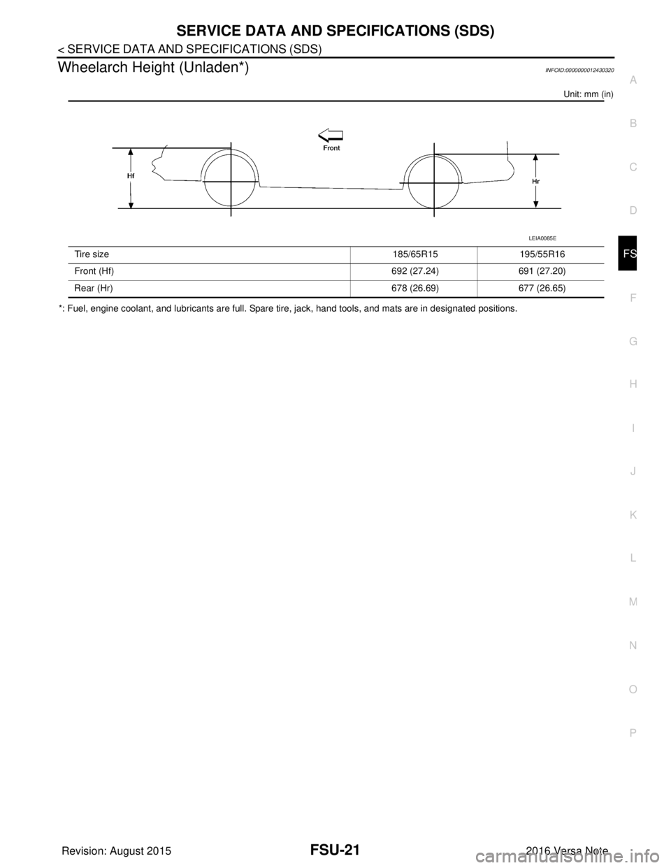
Wheelarch Height (Unladen*)INFOID:0000000012430320
Unit: mm (in)
*: Fuel, engine coolant, and lubricants are full. Spare tire, jack, hand tools, and mats are in designated positions. Tire size
185/65R15195/55R16
Front (Hf) 692 (27.24)691 (27.20)
Rear (Hr) 678 (26.69)677 (26.65)
LEIA0085E
Revision: August 2015 2016 Versa Note
cardiagn.com
Page 1903 of 3641

ABBREVIATIONSGI-15
< HOW TO USE THIS MANUAL >
C
DE
F
G H
I
J
K L
M B
GI
N
O P
E
F
G
H
DLC Data link connector
DTC Diagnostic trouble code
ABBREVIATION DESCRIPTION
E/T Exhaust temperature
EBD Electric brake force distribution
EC Engine control
ECL Engine coolant level
ECM Engine control module
ECT Engine coolant temperature
ECV Electrical control valve
EEPROM Electrically erasable programmable read only memory EFT Engine fuel temperature
EGR Exhaust gas recirculation
EGRT Exhaust gas recirculation temperature EGT Exhaust gas temperature
EOP Engine oil pressure
EP Exhaust pressure
EPR Exhaust pressure regulator
EPS Electronically controlled power steering
ESP Electronic stability program system
EVAP canister Evaporative emission canister EVSE Electric vehicle supply equipment
EXC Exhaust control
ABBREVIATION DESCRIPTION
FC Fan control
FCW Forward collision warning
FIC Fuel injector control
FP Fuel pump
FR Front
FRP Fuel rail pressure
FRT Fuel rail temperature
FTP Fuel tank pressure
FTT Fuel tank temperature
ABBREVIATION DESCRIPTION
GND Ground
GPS Global positioning system
GST Generic scan tool
ABBREVIATION DESCRIPTION
HBMC Hydraulic body-motion control system HDD Hard disk drive
HO2S Heated oxygen sensor
ABBREVIATION
DESCRIPTION
Revision: August 2015 2016 Versa Note
cardiagn.com