2016 NISSAN NOTE engine coolant
[x] Cancel search: engine coolantPage 2332 of 3641

ENGINE MAINTENANCEMA-17
< PERIODIC MAINTENANCE >
C
DE
F
G H
I
J
K L
M B
MA
N
O A
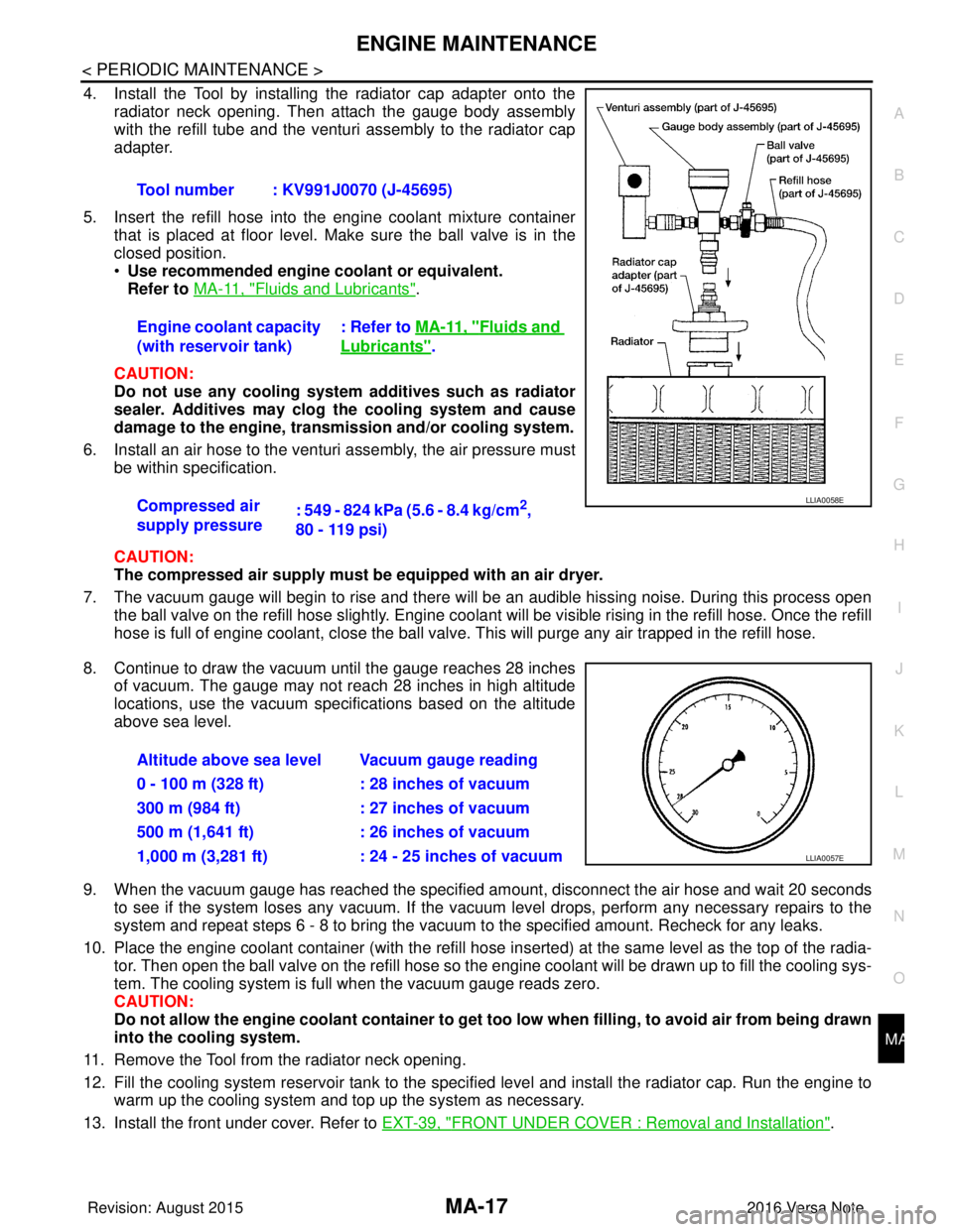
4. Install the Tool by installing the radiator cap adapter onto the
radiator neck opening. Then attach the gauge body assembly
with the refill tube and the venturi assembly to the radiator cap
adapter.
5. Insert the refill hose into the engine coolant mixture container that is placed at floor level. Make sure the ball valve is in the
closed position.
•Use recommended engine coolant or equivalent.
Refer to MA-11, "
Fluids and Lubricants".
CAUTION:
Do not use any cooling system additives such as radiator
sealer. Additives may clog the cooling system and cause
damage to the engine, transmission and/or cooling system.
6. Install an air hose to the venturi assembly, the air pressure must be within specification.
CAUTION:
The compressed air supply must be equipped with an air dryer.
7. The vacuum gauge will begin to rise and there will be an audible hissing noise. During this process open the ball valve on the refill hose slightly. Engine coolant will be visible rising in the refill hose. Once the refill
hose is full of engine coolant, close the ball valve. This will purge any air trapped in the refill hose.
8. Continue to draw the vacuum until the gauge reaches 28 inches of vacuum. The gauge may not reach 28 inches in high altitude
locations, use the vacuum specifications based on the altitude
above sea level.
9. When the vacuum gauge has reached the specified amount, disconnect the air hose and wait 20 seconds
to see if the system loses any vacuum. If the vacuum level drops, perform any necessary repairs to the
system and repeat steps 6 - 8 to br ing the vacuum to the specified amount. Recheck for any leaks.
10. Place the engine coolant container (with the refill hose in serted) at the same level as the top of the radia-
tor. Then open the ball valve on the refill hose so the engine coolant will be drawn up to fill the cooling sys-
tem. The cooling system is full when the vacuum gauge reads zero.
CAUTION:
Do not allow the engine coolant co ntainer to get too low when filling, to avoid air from being drawn
into the cooling system.
11. Remove the Tool from the radiator neck opening.
12. Fill the cooling system reservoir tank to the specif ied level and install the radiator cap. Run the engine to
warm up the cooling system and top up the system as necessary.
13. Install the front under cover. Refer to EXT-39, "
FRONT UNDER COVER : Removal and Installation".
Tool number : KV991J0070 (J-45695)
Engine coolant capacity
(with reservoir tank)
: Refer to
MA-11, "
Fluids and
Lubricants".
Compressed air
supply pressure : 549 - 824 kPa (5.6 - 8.4 kg/cm
2,
80 - 119 psi)LLIA0058E
Altitude above sea level Vacuum gauge reading
0 - 100 m (328 ft) : 28 inches of vacuum
300 m (984 ft) : 27 inches of vacuum
500 m (1,641 ft) : 26 inches of vacuum
1,000 m (3,281 ft) : 24 - 25 inches of vacuum
LLIA0057E
Revision: August 2015 2016 Versa Note
cardiagn.com
Page 2333 of 3641

MA-18
< PERIODIC MAINTENANCE >
ENGINE MAINTENANCE
ENGINE COOLANT : Flushing Cooling System
INFOID:0000000012432255
1. Install radiator drain plug and reservoir tank, if removed.
CAUTION:
Be sure to clean drain plug and install with new O-ring.
2. If water drain plugs on cylinder block were removed, close and tighten them. Refer to EM-93, "
Exploded
View".
3. Remove air duct from between air cleaner case and electric throttle control actuator. Refer to EM-26,
"Removal and Installation".
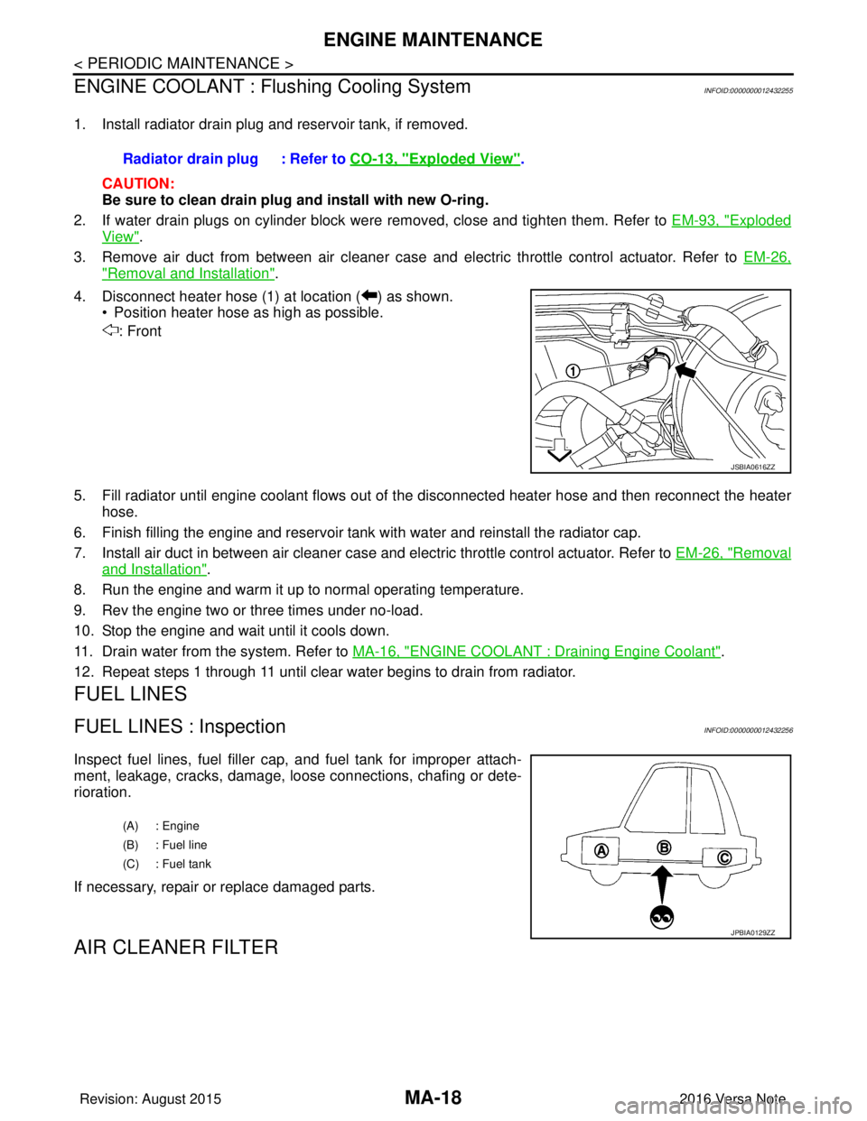
4. Disconnect heater hose (1) at location ( ) as shown. • Position heater hose as high as possible.
: Front
5. Fill radiator until engine coolant flows out of the disconnected heater hose and then reconnect the heater
hose.
6. Finish filling the engine and reservoir tank with water and reinstall the radiator cap.
7. Install air duct in between air cleaner case and electric throttle control actuator. Refer to EM-26, "
Removal
and Installation".
8. Run the engine and warm it up to normal operating temperature.
9. Rev the engine two or three times under no-load.
10. Stop the engine and wait until it cools down.
11. Drain water from the system. Refer to MA-16, "
ENGINE COOLANT : Draining Engine Coolant".
12. Repeat steps 1 through 11 until clear water begins to drain from radiator.
FUEL LINES
FUEL LINES : InspectionINFOID:0000000012432256
Inspect fuel lines, fuel filler cap, and fuel tank for improper attach-
ment, leakage, cracks, damage, l oose connections, chafing or dete-
rioration.
If necessary, repair or replace damaged parts.
AIR CLEANER FILTER
Radiator drain plug : Refer to CO-13, "Exploded View".
JSBIA0616ZZ
(A) : Engine
(B) : Fuel line
(C) : Fuel tank
JPBIA0129ZZ
Revision: August 2015 2016 Versa Note
cardiagn.com
Page 2335 of 3641

MA-20
< PERIODIC MAINTENANCE >
ENGINE MAINTENANCE
2. Remove the air cleaner filter (1) from the air cleaner body.
INSTALLATION
Installation is in the reverse order of removal.
NOTE:
Check that the air cleaner filter is securely placed in the air cleaner body.
ENGINE OIL
ENGINE OIL : InspectionINFOID:0000000012432259
ENGINE OIL LEVEL
NOTE:
Before starting engine, position the vehicle so that it is level and check the engine oil level. If engine is already
started, stop it and allow 10 minutes before checking.
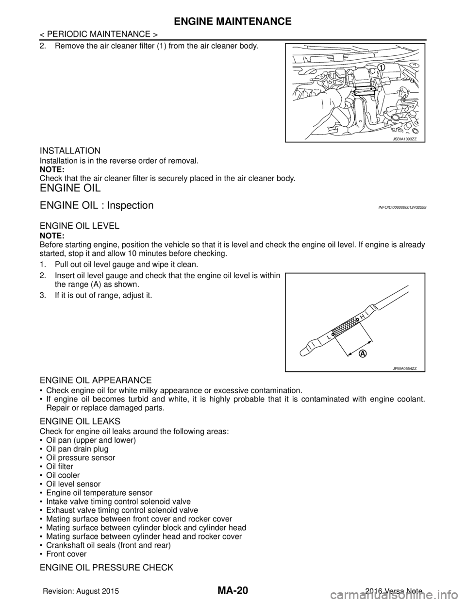
1. Pull out oil level gauge and wipe it clean.
2. Insert oil level gauge and check that the engine oil level is withinthe range (A) as shown.
3. If it is out of range, adjust it.
ENGINE OIL APPEARANCE
• Check engine oil for white milky appearance or excessive contamination.
• If engine oil becomes turbid and white, it is highl y probable that it is contaminated with engine coolant.
Repair or replace damaged parts.
ENGINE OIL LEAKS
Check for engine oil leaks around the following areas:
• Oil pan (upper and lower)
• Oil pan drain plug
• Oil pressure sensor
• Oil filter
• Oil cooler
• Oil level sensor
• Engine oil temperature sensor
• Intake valve timing control solenoid valve
• Exhaust valve timing control solenoid valve
• Mating surface between front cover and rocker cover
• Mating surface between cylinder block and cylinder head
• Mating surface between cylinder head and rocker cover
• Crankshaft oil seals (front and rear)
• Front cover
ENGINE OIL PRESSURE CHECK
JSBIA1093ZZ
JPBIA0554ZZ
Revision: August 2015 2016 Versa Note
cardiagn.com
Page 2367 of 3641
![NISSAN NOTE 2016 Service Repair Manual MWI
COMPONENT PARTSMWI-9
< SYSTEM DESCRIPTION > [TYPE A]
C
D
E
F
G H
I
J
K L
M B A
O P
METER SYSTEM : Combination MeterINFOID:0000000012432542
The combination meter controls the following items a ccor NISSAN NOTE 2016 Service Repair Manual MWI
COMPONENT PARTSMWI-9
< SYSTEM DESCRIPTION > [TYPE A]
C
D
E
F
G H
I
J
K L
M B A
O P
METER SYSTEM : Combination MeterINFOID:0000000012432542
The combination meter controls the following items a ccor](/manual-img/5/57363/w960_57363-2366.png)
MWI
COMPONENT PARTSMWI-9
< SYSTEM DESCRIPTION > [TYPE A]
C
D
E
F
G H
I
J
K L
M B A
O P
METER SYSTEM : Combination MeterINFOID:0000000012432542
The combination meter controls the following items a ccording to the signals received from each unit via CAN
communication and the signals from switches and sensors:
• Measuring instruments
• Indicator lamps
• Warning lamps
• Meter illumination control
• Information display
ARRANGEMENT OF COMBINATION METER
6. ECM Transmits the following signals to the combination meter via CAN communication:
• Engine speed signal
• Engine coolant temperature signal
• Fuel consumption monitor signal
• Engine oil pressure sensor signal
Refer to EC-14, "
ENGINE CONTROL SYSTEM : ComponentPartsLocation" for de-
tailed installation location.
7. BCM Transmits the following signals to the combination meter via CAN communication:
• Door switch signal
• Buzzer signal
Refer to BCS-137, "
Removal and Installation" for detailed installation location.
8. Combination meter Refer to MWI-9, "
METER SYSTEM : Combination Meter".
9. Fuel level sensor unit and fuel pump
(fuel level sensor) Transmits the fuel level sensor signal to the combination meter.
No.
Component Function
U: USAEU: Except USA
AWNIA3633ZZ
Revision: August 2015 2016 Versa Note
cardiagn.com
Page 2368 of 3641
![NISSAN NOTE 2016 Service Repair Manual MWI-10
< SYSTEM DESCRIPTION >[TYPE A]
SYSTEM
SYSTEM
METER SYSTEM
METER SYSTEM : System DescriptionINFOID:0000000012432543
SYSTEM DIAGRAM
COMBINATION METER INPUT SIGNAL (CAN COMMUNICATION SIGNAL)
DESCR NISSAN NOTE 2016 Service Repair Manual MWI-10
< SYSTEM DESCRIPTION >[TYPE A]
SYSTEM
SYSTEM
METER SYSTEM
METER SYSTEM : System DescriptionINFOID:0000000012432543
SYSTEM DIAGRAM
COMBINATION METER INPUT SIGNAL (CAN COMMUNICATION SIGNAL)
DESCR](/manual-img/5/57363/w960_57363-2367.png)
MWI-10
< SYSTEM DESCRIPTION >[TYPE A]
SYSTEM
SYSTEM
METER SYSTEM
METER SYSTEM : System DescriptionINFOID:0000000012432543
SYSTEM DIAGRAM
COMBINATION METER INPUT SIGNAL (CAN COMMUNICATION SIGNAL)
DESCRIPTION
Combination Meter
• The combination meter receives necessary signals from each unit, switch, and sensor to control the follow-
ing functions.
- Measuring instruments
- Warning lamps
- Indicator lamps
- Meter illumination control
- Information display
• The combination meter incorporates a buzzer function that sounds an audible alarm with the integrated buzzer device. Refer to WCS-7, "
WARNING CHIME SYSTEM : System Description" for further details.
AWNIA3080GB
Transmit unit Signal name
ABS actuator and electric unit (c ontrol unit) Vehicle speed signal
BCM Door switch signal
Buzzer signal
TCM Shift position signal
ECM Engine speed signal
Engine coolant temperature signal
Engine oil pressure signal
Fuel consumption signal
Loose fuel cap signal
Revision: August 2015
2016 Versa Note
cardiagn.com
Page 2369 of 3641
![NISSAN NOTE 2016 Service Repair Manual MWI
SYSTEMMWI-11
< SYSTEM DESCRIPTION > [TYPE A]
C
D
E
F
G H
I
J
K L
M B A
O P
• The combination meter includes an on board diagnosis function.
• The combination meter can be diagnosed with CONSUL NISSAN NOTE 2016 Service Repair Manual MWI
SYSTEMMWI-11
< SYSTEM DESCRIPTION > [TYPE A]
C
D
E
F
G H
I
J
K L
M B A
O P
• The combination meter includes an on board diagnosis function.
• The combination meter can be diagnosed with CONSUL](/manual-img/5/57363/w960_57363-2368.png)
MWI
SYSTEMMWI-11
< SYSTEM DESCRIPTION > [TYPE A]
C
D
E
F
G H
I
J
K L
M B A
O P
• The combination meter includes an on board diagnosis function.
• The combination meter can be diagnosed with CONSULT.
METER CONTROL FUNCTION LIST
METER SYSTEM : Fail-safeINFOID:0000000012432544
The combination meter activates the fail-safe contro l if CAN communication with each unit is malfunctioning.
System DescriptionReference
Measuring instruments Speedometer
Indicates vehicle speed. MWI-12,
"SPEEDOME-
TER : System De-
scription"
Tachometer
Indicates engine speed. MWI-12, "
TA -
CHOMETER :
System Descrip-
tion"
Shift position indicator
Indicates shift position.MWI-13, "
SHIFT
POSITION INDI-
CATOR : System
Description"
Warning lamp/indicator
lamp
Engine oil pressure warning lamp The warning lamp turns ON or turns OFF,
according to engine hydraulic pressure. MWI-13, "
OIL
PRESSURE
WARNING LAMP
: System Descrip-
tion"
Meter illumination con-
trol
Meter illumination control function
Controls the back light of combination meter. MWI-13, "
METER
ILLUMINATION
CONTROL : Sys-
tem Description"
Information displayOdo/trip meter Indicates mileage.
MWI-14, "
INFOR-
MATION DIS-
PLAY : System
Description"
Engine coolant temperature gauge Indicates engine coolant temperature.
Fuel gaugeIndicates fuel level.
Loose fuel cap warning Indicates loose fuel cap.
Low fuel warning Indicates fuel level.
Trip computer Instant fuel consumption Displays current fuel consumption.
Average fuel consumption Displays average fuel consumption.
Distance to empty Displays distance to empty.
Travel distance
Displays mileage.
Function Specifications
Speedometer Reset to zero by suspending communication.
Tachometer
Illumination control When suspending communication, changes to nighttime mode.
Shift position indicator When suspending communication, not indicate.
Information display Trip com-
puterCurrent fuel consump-
tion
• When reception time of an abnormal signal is 2 seconds or
less, the last received datum is used for calculation to indi-
cate the result.
• When reception time of an abnormal signal is more than two
seconds, the last result calculated during normal condition is
indicated.
Average fuel consump-
tion
Distance to empty
Engine coolant temperature gauge Reset to zero by suspending communication.
Odo/trip meter An indicated value is maintained at communications blackout.
Buzzer The buzzer turns OFF by suspending communication.
Revision: August 2015 2016 Versa Note
cardiagn.com
Page 2372 of 3641
![NISSAN NOTE 2016 Service Repair Manual MWI-14
< SYSTEM DESCRIPTION >[TYPE A]
SYSTEM
• The combination meter turns OFF meter illumination when the following conditions are satisfied.
INFORMATION DISPLAY
INFORMATION DISPLAY : System Descri NISSAN NOTE 2016 Service Repair Manual MWI-14
< SYSTEM DESCRIPTION >[TYPE A]
SYSTEM
• The combination meter turns OFF meter illumination when the following conditions are satisfied.
INFORMATION DISPLAY
INFORMATION DISPLAY : System Descri](/manual-img/5/57363/w960_57363-2371.png)
MWI-14
< SYSTEM DESCRIPTION >[TYPE A]
SYSTEM
• The combination meter turns OFF meter illumination when the following conditions are satisfied.
INFORMATION DISPLAY
INFORMATION DISPLAY : System DescriptionINFOID:0000000012432550
SYSTEM DIAGRAM
DESRIPTION
• The combination meter receives signals from swit
ches, sensors and modules for operating the following
functions on the information display.
- Odo/trip meter
- Engine coolant temperature gauge
- Fuel gauge
- Trip computer
- Interrupt indication
- Meter illumination level
- Low fuel warning
- Loose fuel cap warning
ODO/TRIP METER
The combination meter calculates mileage using the v ehicle speed signal from the ABS actuator and electric
unit (control unit) and displays the mileage on the information display.
ENGINE COOLANT TEMPERATURE GAUGE
The engine coolant temperature gauge indicates the engine coolant temperature.
The ECM provides an engine coolant temperature signal to the combination meter via CAN communication.
FUEL GAUGE
Control Outline
The fuel level sensor unit sends a variable resistor signal to the combination meter. The fuel gauge indicates
the approximate fuel level in the fuel tank.
Refuel Control
The unit detects the driver is refueling the vehicle and accelerates the fuel gauge segment movement if the
fuel level changes by 9 (2-3/8 US, 2 lmp gal) or more.
Condition
Combination switch (Lighting switch) OFF
AWNIA2439GB
Revision: August 2015 2016 Versa Note
cardiagn.com
Page 2376 of 3641
![NISSAN NOTE 2016 Service Repair Manual MWI-18
< SYSTEM DESCRIPTION >[TYPE A]
DIAGNOSIS SYSTEM (COMBINATION METER)
NOTE:
• If any of the meters or gauges is not activated, replace combination meter.
• The figure is reference.
CONSULT Fu NISSAN NOTE 2016 Service Repair Manual MWI-18
< SYSTEM DESCRIPTION >[TYPE A]
DIAGNOSIS SYSTEM (COMBINATION METER)
NOTE:
• If any of the meters or gauges is not activated, replace combination meter.
• The figure is reference.
CONSULT Fu](/manual-img/5/57363/w960_57363-2375.png)
MWI-18
< SYSTEM DESCRIPTION >[TYPE A]
DIAGNOSIS SYSTEM (COMBINATION METER)
NOTE:
• If any of the meters or gauges is not activated, replace combination meter.
• The figure is reference.
CONSULT Function (METER/M&A)INFOID:0000000012432553
APPLICATION ITEMS
CONSULT can display each diagnostic item
using the diagnostic test modes shown.
SELF DIAG RESULT
Refer to MWI-24, "DTC Index".
DATA MONITOR
Display Item List
X: Applicable
METER/M&A Diagnosis mode Description
Self Diagnostic Result The combination meter self-diagnosis results.
Data Monitor Displays combination meter input/output data in real time.
Work support Supports combination meter diagnosis.
ECU Identification The combination meter part number is displayed.
Warning History Lighting history of the warning lamp and indicator lamp can be checked.
Display item [Unit]MAIN
SIGNALS Description
SPEED METER
[mph] or [km/h] X Displays the value of vehicle speed signal.
SPEED OUTPUT
[mph] or [km/h] X Displays the value of vehicle speed signal, which is transmitted to each unit with CAN communication.
ODO OUTPUT
[Mi] or [km] Displays odometer signal value transmitted to other units via CAN communication.
TACHO METER
[rpm] X Displays the value of engine speed signal, which is input from ECM.
FUEL METER
[L] X Displays the fuel level.
W TEMP METER
[ ° F] or [ °C] X Displays the value of engine coolant temperature signal, which is input from ECM.
ABS W/L
[ON/OFF] Displays [ON/OFF] conditio
n of ABS warning indicator
VDC/TCS IND
[ON/OFF] Displays [ON/OFF] condition
of VDC OFF indicator lamp.
SLIP IND
[ON/OFF] Displays [ON/OFF] condition of SLIP indicator lamp.
BRAKE W/L
[ON/OFF] Displays [ON/OFF] condition of brake warning indicator.
DOOR W/L
[ON/OFF] Displays [ON/OFF] condition of door warning indicator.
HI-BEAM IND
[ON/OFF] Displays [ON/OFF] condition of high beam indicator.
TURN IND
[ON/OFF] Displays [ON/OFF] condition of turn indicator.
LIGHT IND
[ON/OFF] Displays [ON/OFF] condition of light indicator.
OIL W/L
[ON/OFF] Displays [ON/OFF] condition of engine oil pressure warning indicator.
Revision: August 2015
2016 Versa Note
cardiagn.com