2016 NISSAN NOTE check engine
[x] Cancel search: check enginePage 619 of 3641
CHG-24
< DTC/CIRCUIT DIAGNOSIS >
L TERMINAL CIRCUIT (OPEN)
L TERMINAL CIRCUIT (OPEN)
DescriptionINFOID:0000000012431253
The “L” terminal circuit controls the charge warning lamp. The charge warning lamp turns ON when the igni-
tion switch is set to ON or START. When the generator is providing sufficient voltage with the engine running,
the charge warning lamp turns OFF. If the charge warn ing lamp illuminates with the engine running, a malfunc-
tion is indicated.
Diagnosis ProcedureINFOID:0000000012431254
Regarding Wiring Diagram information. Refer to CHG-9, "Wiring Diagram".
1.CHECK “L” TERMINAL CONNECTION
1. Turn ignition switch OFF.
2. Check if “L” terminal is clean and tight.
Is the inspection result normal?
YES >> GO TO 2.
NO >> Repair “L” terminal connection. Confirm repa ir by performing complete Charging system test
using EXP-800 NI or GR8-1200 NI (if available). Refer to applicable Instruction Manual for proper
testing procedures.
2.CHECK “L” TERMIN AL CIRCUIT (OPEN)
1. Disconnect the generator connector.
2. Apply ground to generator harness connector terminal.
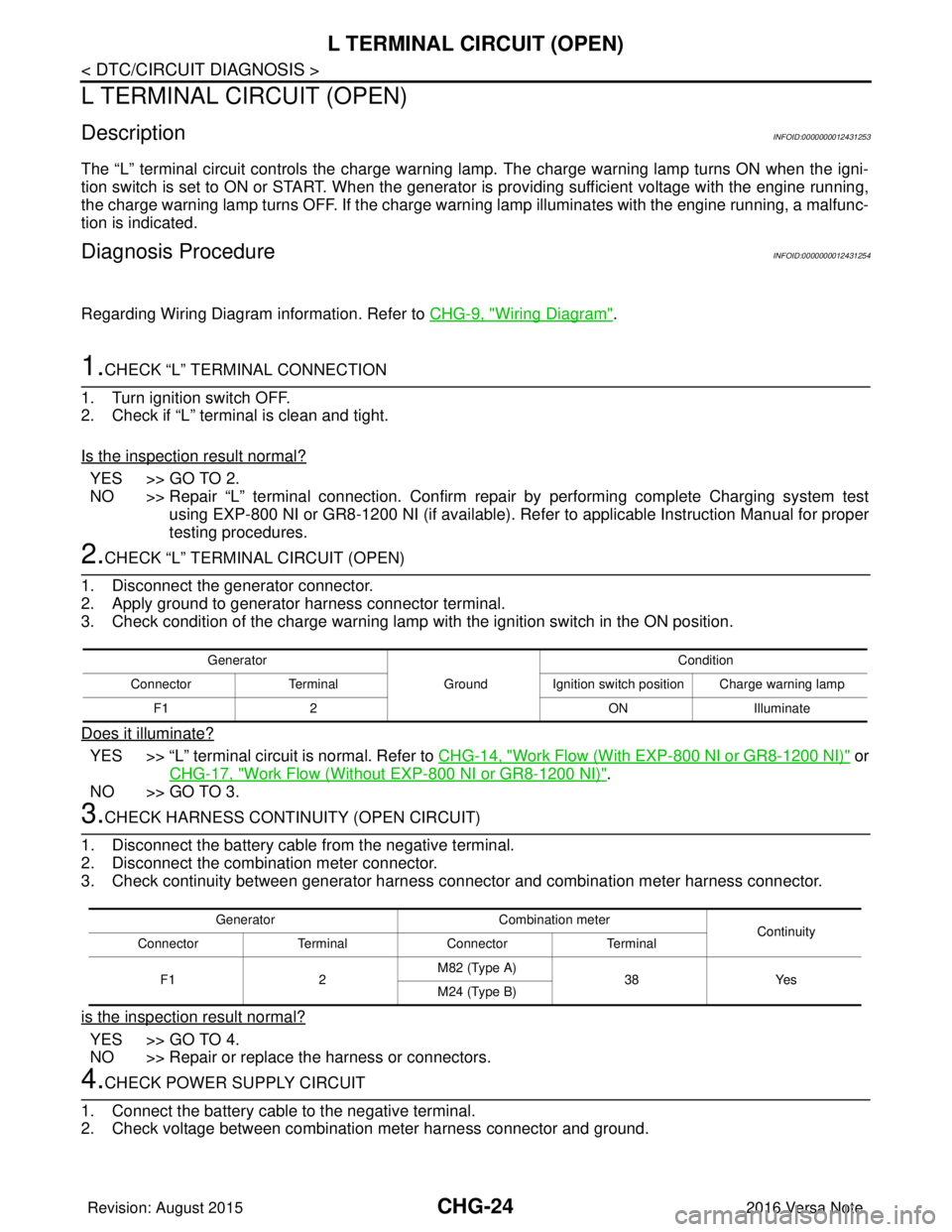
3. Check condition of the charge warning lamp with the ignition switch in the ON position.
Does it illuminate?
YES >> “L” terminal circuit is normal. Refer to CHG-14, "Work Flow (With EXP-800 NI or GR8-1200 NI)" or
CHG-17, "
Work Flow (Without EXP-800 NI or GR8-1200 NI)".
NO >> GO TO 3.
3.CHECK HARNESS CONTI NUITY (OPEN CIRCUIT)
1. Disconnect the battery cable from the negative terminal.
2. Disconnect the combination meter connector.
3. Check continuity between generator harness c onnector and combination meter harness connector.
is the inspection result normal?
YES >> GO TO 4.
NO >> Repair or replace the harness or connectors.
4.CHECK POWER SUPPLY CIRCUIT
1. Connect the battery cable to the negative terminal.
2. Check voltage between combination meter harness connector and ground.
Generator
GroundCondition
Connector Terminal Ignition switch position Charge warning lamp
F1 2 ONIlluminate
Generator Combination meter
Continuity
Connector TerminalConnector Terminal
F1 2M82 (Type A)
38Yes
M24 (Type B)
Revision: August 2015 2016 Versa Note
cardiagn.com
Page 621 of 3641
CHG-26
< DTC/CIRCUIT DIAGNOSIS >
L TERMINAL CIRCUIT (SHORT)
L TERMINAL CIRCUIT (SHORT)
DescriptionINFOID:0000000012431255
The terminal “L” circuit controls the charge warning lamp. The charge warning lamp turns ON when the igni-
tion switch is set to ON or START. When the generator is providing sufficient voltage with the engine running,
the charge warning lamp turns off. If the charge warning lamp illuminates with the engine running, a malfunc-
tion is indicated.
Diagnosis ProcedureINFOID:0000000012431256
Regarding Wiring Diagram information, refer to CHG-9, "Wiring Diagram".
1.CHECK “L” TERMINAL CIRCUIT (SHORT)
1. Turn ignition switch OFF.
2. Disconnect generator connector.
3. Turn ignition switch ON.
Does charge warning lamp illuminate?
YES >> GO TO 2.
NO >> Refer to CHG-14, "
Work Flow (With EXP-800 NI or GR8-1200 NI)" or CHG-17, "Work Flow (With-
out EXP-800 NI or GR8-1200 NI)".
2.CHECK HARNESS CONTI NUITY (SHORT CIRCUIT)
1. Turn ignition switch OFF.
2. Disconnect the battery cable from the negative terminal.
3. Disconnect combination meter connector.
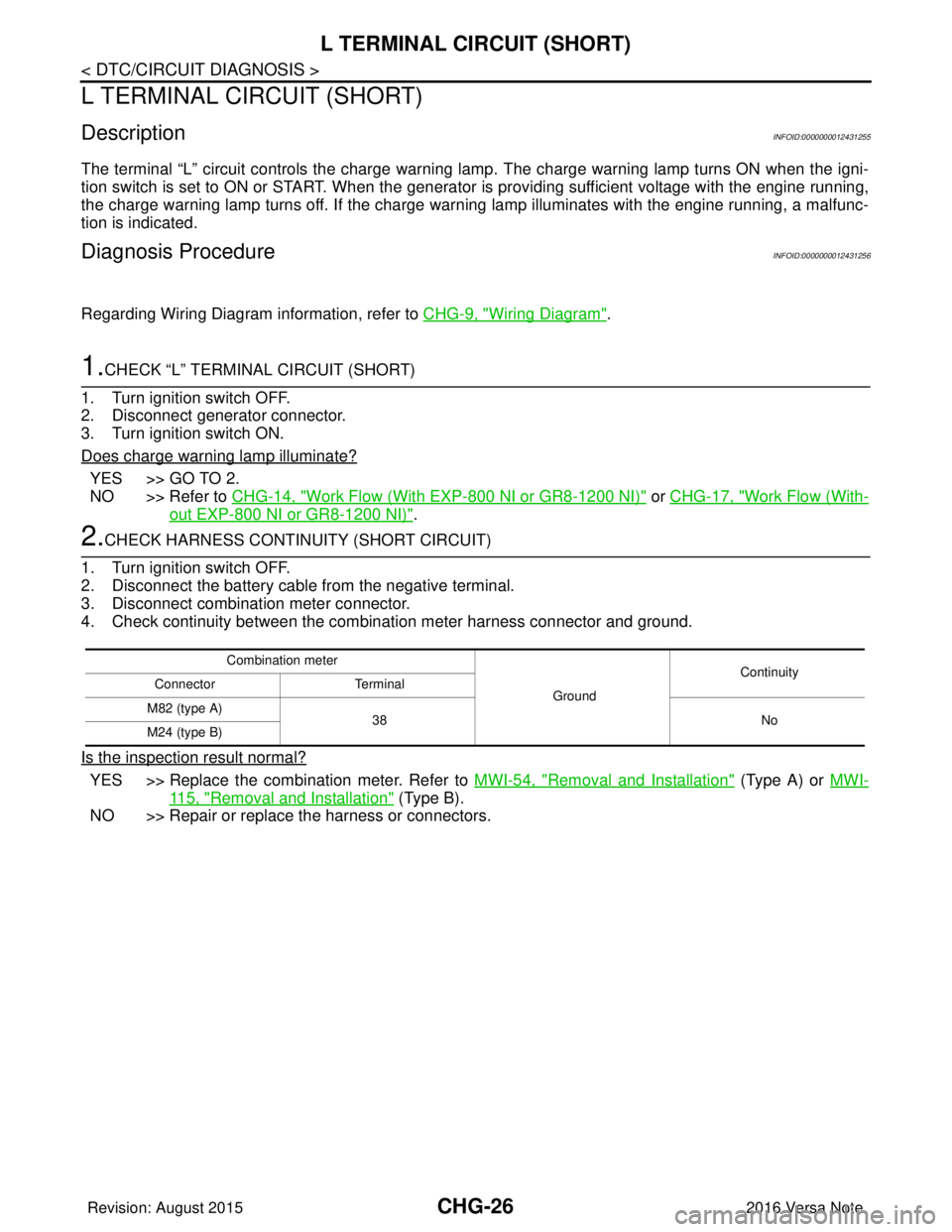
4. Check continuity between the combination meter harness connector and ground.
Is the inspection result normal?
YES >> Replace the combination meter. Refer to MWI-54, "Removal and Installation" (Type A) or MWI-
115, "Removal and Installation" (Type B).
NO >> Repair or replace the harness or connectors.
Combination meter
GroundContinuity
Connector Terminal
M82 (type A) 38 No
M24 (type B)
Revision: August 2015 2016 Versa Note
cardiagn.com
Page 631 of 3641
CLUTCH PEDALCL-5
< PERIODIC MAINTENANCE >
CEF
G H
I
J
K L
M A
B
CL
N
O P
PERIODIC MAINTENANCE
CLUTCH PEDAL
Inspection and AdjustmentINFOID:0000000012432215
INSPECTION
The Height of Clutch Pedal
1. Turn the floor carpet.
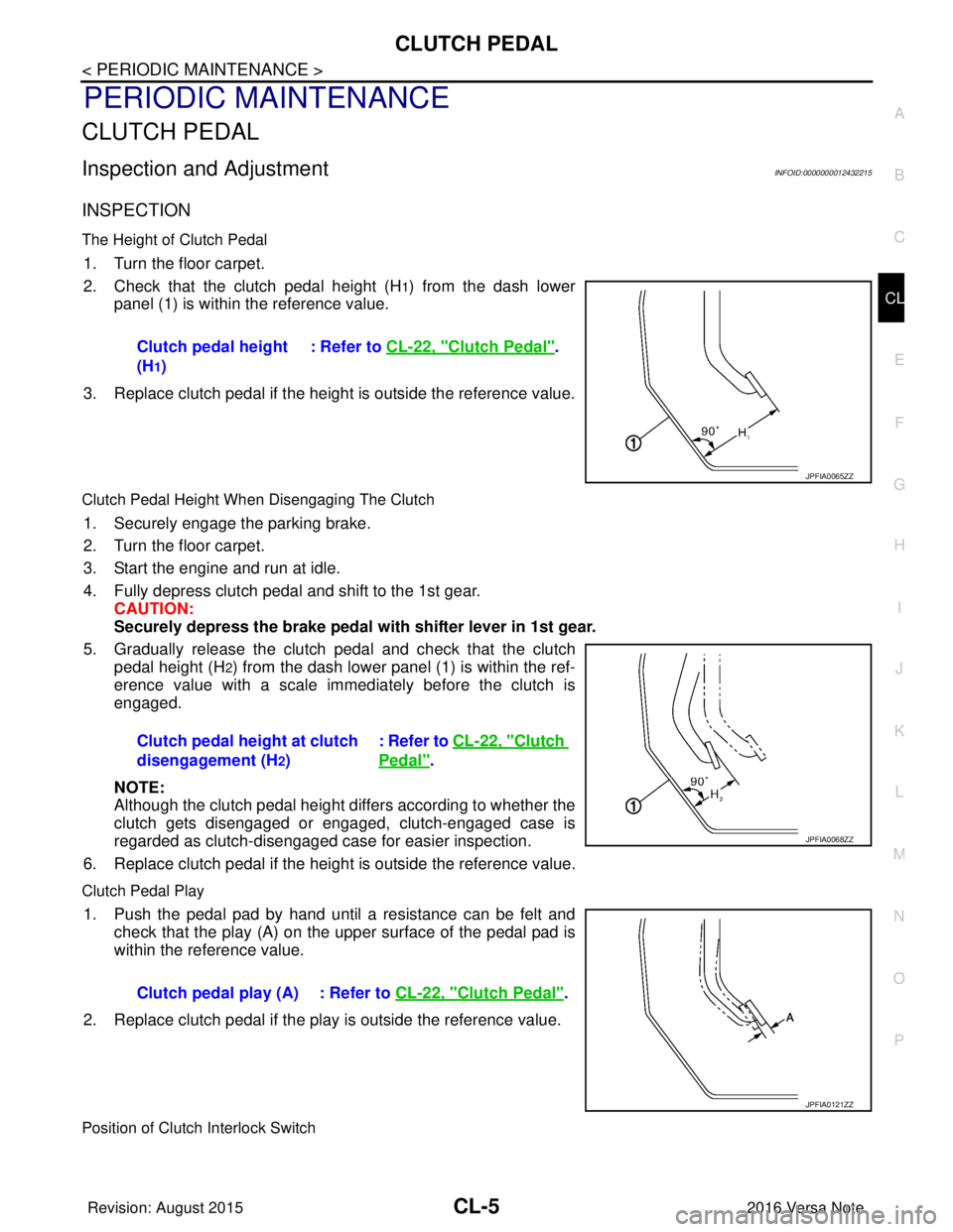
2. Check that the clutch pedal height (H
1) from the dash lower
panel (1) is within the reference value.
3. Replace clutch pedal if the height is outside the reference value.
Clutch Pedal Height When Disengaging The Clutch
1. Securely engage the parking brake.
2. Turn the floor carpet.
3. Start the engine and run at idle.
4. Fully depress clutch pedal and shift to the 1st gear. CAUTION:
Securely depress the brake pedal with shifter lever in 1st gear.
5. Gradually release the clutch pedal and check that the clutch pedal height (H
2) from the dash lower panel (1) is within the ref-
erence value with a scale immediately before the clutch is
engaged.
NOTE:
Although the clutch pedal height differs according to whether the
clutch gets disengaged or engaged, clutch-engaged case is
regarded as clutch-disengaged case for easier inspection.
6. Replace clutch pedal if the height is outside the reference value.
Clutch Pedal Play
1. Push the pedal pad by hand until a resistance can be felt and check that the play (A) on the upper surface of the pedal pad is
within the reference value.
2. Replace clutch pedal if the play is outside the reference value.
Position of Clutch Interlock Switch
Clutch pedal height
(H
1) : Refer to
CL-22, "
Clutch Pedal".
JPFIA0065ZZ
Clutch pedal height at clutch
disengagement (H
2) : Refer to CL-22, "
Clutch
Pedal".
JPFIA0068ZZ
Clutch pedal play (A) : Refer to
CL-22, "Clutch Pedal".
JPFIA0121ZZ
Revision: August 2015 2016 Versa Note
cardiagn.com
Page 633 of 3641
CLUTCH FLUIDCL-7
< PERIODIC MAINTENANCE >
CEF
G H
I
J
K L
M A
B
CL
N
O P
CLUTCH FLUID
InspectionINFOID:0000000012432216
CLUTCH FLUID LEAKS
• Check clutch line for cracks, deterioration or other damage. Replace any damaged parts.
• Check for clutch fluid leaks by fully depressing clutch pedal while engine is running. CAUTION:
If leaks occur around connections, reinstall th e lines or replace damaged parts, if necessary.
CLUTCH FLUID LEVEL
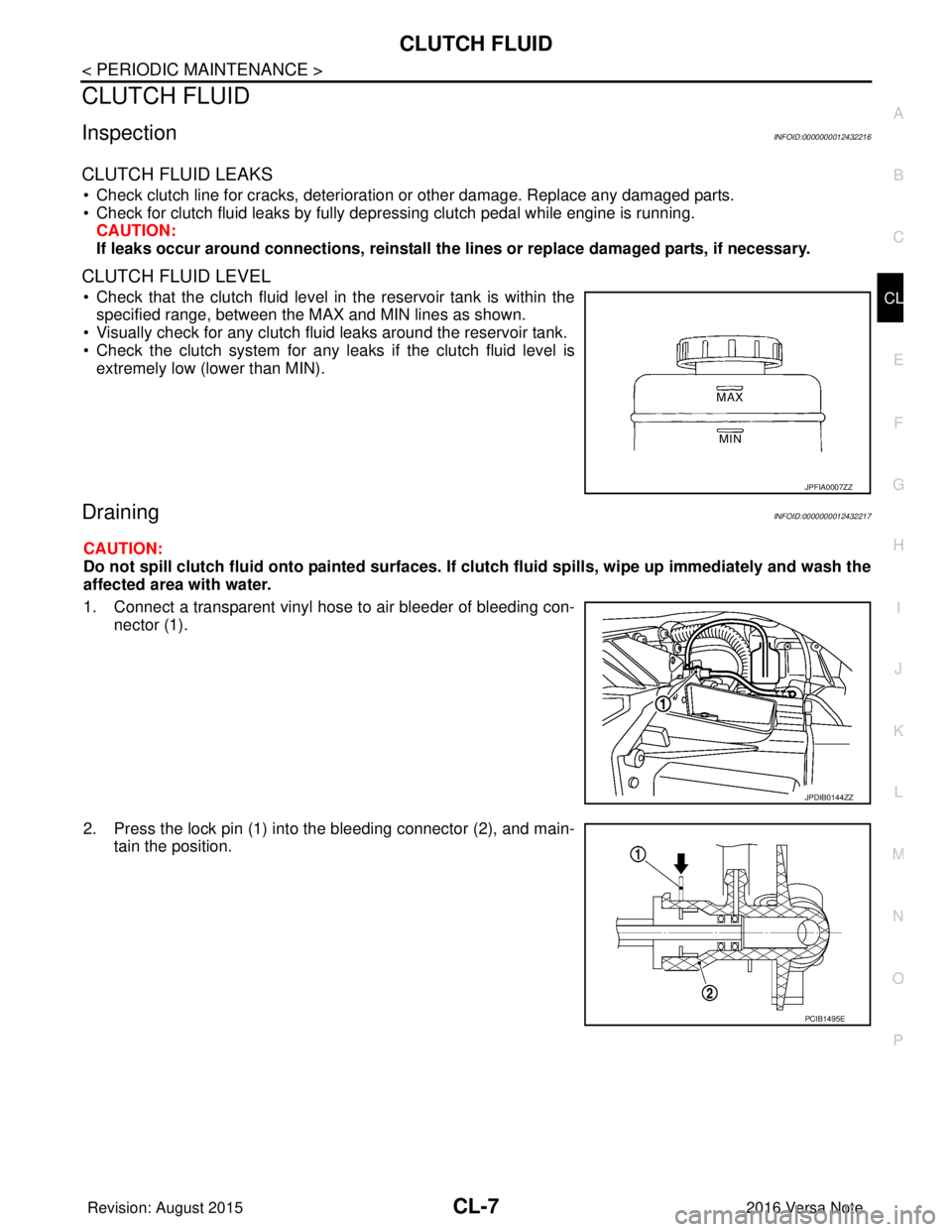
• Check that the clutch fluid level in the reservoir tank is within the
specified range, between the MAX and MIN lines as shown.
• Visually check for any clutch fluid leaks around the reservoir tank.
• Check the clutch system for any leaks if the clutch fluid level is
extremely low (lower than MIN).
DrainingINFOID:0000000012432217
CAUTION:
Do not spill clutch fluid onto painted surfaces. If clutch fluid spills, wipe up immediately and wash the
affected area with water.
1. Connect a transparent vinyl hose to air bleeder of bleeding con-
nector (1).
2. Press the lock pin (1) into the bleeding connector (2), and main- tain the position.
JPFIA0007ZZ
JPDIB0144ZZ
PCIB1495E
Revision: August 2015 2016 Versa Note
cardiagn.com
Page 644 of 3641

CL-18
< UNIT REMOVAL AND INSTALLATION >
CSC (CONCENTRIC SLAVE CYLINDER)
• Do not insert and operate CSC when transaxle is removed. Piston and stopper of CSC compo-nents may fall off.
2. Install engine and transaxle assembly. Refer to EM-87, "
Removal and Installation".
Inspection and AdjustmentINFOID:0000000012432232
INSPECTION AFTER INSTALLATION
Check for clutch fluid leaks and clutch fluid level. Refer to CL-7, "Inspection".
ADJUSTMENT AFTER INSTALLATION
Perform the air bleeding. Refer to CL-9, "Air Bleeding".
Revision: August 2015 2016 Versa Note
cardiagn.com
Page 646 of 3641
CL-20
< UNIT REMOVAL AND INSTALLATION >
CLUTCH DISC AND CLUTCH COVER
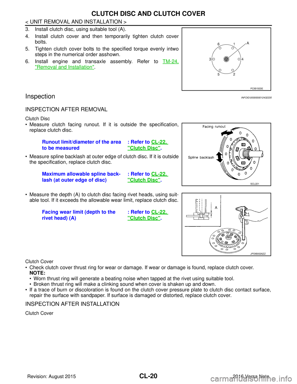
3. Install clutch disc, using suitable tool (A).
4. Install clutch cover and then temporarily tighten clutch coverbolts.
5. Tighten clutch cover bolts to the specified torque evenly intwo steps in the numerical order asshown.
6. Install engine and transaxle assembly. Refer to TM-24,
"Removal and Installation".
InspectionINFOID:0000000012432235
INSPECTION AFTER REMOVAL
Clutch Disc
• Measure clutch facing runout. If it is outside the specification,
replace clutch disc.
• Measure spline backlash at outer edge of clutch disc. If it is outside the specification, replace clutch disc.
• Measure the depth (A) to clutch disc facing rivet heads, using suit- able tool. If it exceeds the allowable wear limit, replace clutch disc.
Clutch Cover
• Check clutch cover thrust ring for wear or damage. If wear or damage is found, replace clutch cover.
NOTE:
• Worn thrust ring will generate a beating noise when tapped at the rivet using suitable tool.
• Broken thrust ring will make a clinking sound when cover is shaken up and down.
• If a trace of burn or discoloration is found on the clutch cover pressure plate to clutch disc contact surface,
repair the surface with sandpaper. If surface is damaged or distorted, replace clutch cover.
INSPECTION AFTER INSTALLATION
Clutch Cover
PCIB1503E
Runout limit/diameter of the area
to be measured : Refer to
CL-22,
"Clutch Disc".
Maximum allowable spline back-
lash (at outer edge of disc) : Refer to
CL-22,
"Clutch Disc".SCL221
Facing wear limit (depth to the
rivet head) (A) : Refer to
CL-22,
"Clutch Disc".
JPDIB0026ZZ
Revision: August 2015 2016 Versa Note
cardiagn.com
Page 647 of 3641
CLUTCH DISC AND CLUTCH COVERCL-21
< UNIT REMOVAL AND INSTALLATION >
CEF
G H
I
J
K L
M A
B
CL
N
O P
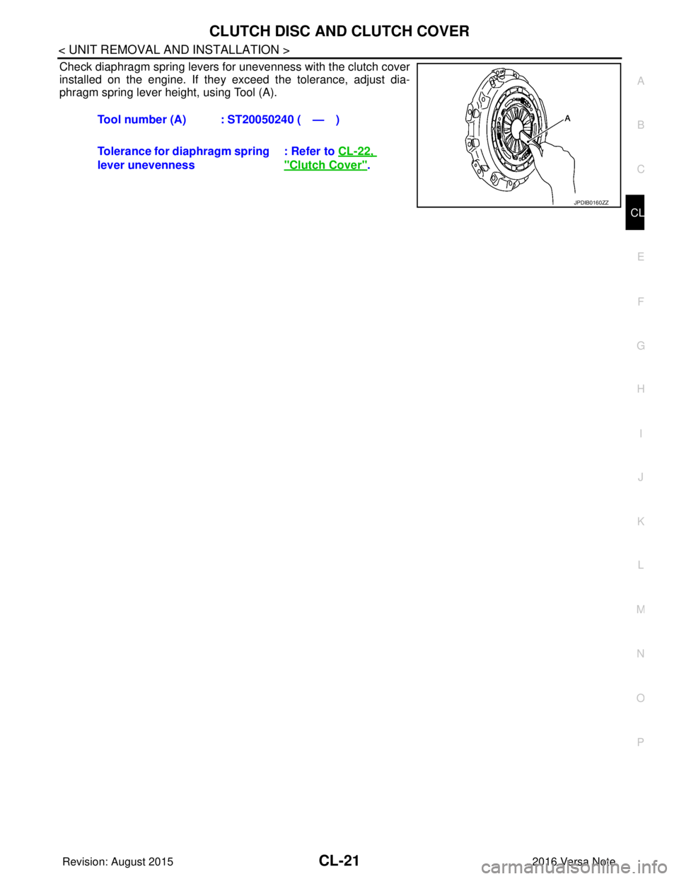
Check diaphragm spring levers for unevenness with the clutch cover
installed on the engine. If they exceed the tolerance, adjust dia-
phragm spring lever height, using Tool (A). Tool number (A) : ST20050240 ( — )
Tolerance for diaphragm spring
lever unevenness : Refer to
CL-22,
"Clutch Cover".
JPDIB0160ZZ
Revision: August 2015 2016 Versa Note
cardiagn.com
Page 698 of 3641
![NISSAN NOTE 2016 Service Repair Manual PRECAUTIONSDLK-9
< PRECAUTION > [WITH INTELLIGENT KEY SYSTEM]
C
D
E
F
G H
I
J
L
M A
B
DLK
N
O P
PRECAUTION
PRECAUTIONS
Precaution for Supplemental Restraint System (SRS) "AIR BAG" and "SEAT BELT
PRE NISSAN NOTE 2016 Service Repair Manual PRECAUTIONSDLK-9
< PRECAUTION > [WITH INTELLIGENT KEY SYSTEM]
C
D
E
F
G H
I
J
L
M A
B
DLK
N
O P
PRECAUTION
PRECAUTIONS
Precaution for Supplemental Restraint System (SRS) "AIR BAG" and "SEAT BELT
PRE](/manual-img/5/57363/w960_57363-697.png)
PRECAUTIONSDLK-9
< PRECAUTION > [WITH INTELLIGENT KEY SYSTEM]
C
D
E
F
G H
I
J
L
M A
B
DLK
N
O P
PRECAUTION
PRECAUTIONS
Precaution for Supplemental Restraint System (SRS) "AIR BAG" and "SEAT BELT
PRE-TENSIONER"
INFOID:0000000012429960
The Supplemental Restraint System such as “AIR BAG” and “SEAT BELT PRE-TENSIONER”, used along
with a front seat belt, helps to reduce the risk or severi ty of injury to the driver and front passenger for certain
types of collision. Information necessary to service the system safely is included in the SR and SB section of
this Service Manual.
WARNING:
• To avoid rendering the SRS inoper ative, which could increase the risk of personal injury or death in
the event of a collision which would result in air bag inflation, all maintenance must be performed by
an authorized NISSAN/INFINITI dealer.
• Improper maintenance, including in correct removal and installation of the SRS, can lead to personal
injury caused by unintentional act ivation of the system. For removal of Spiral Cable and Air Bag
Module, see the SR section.
• Do not use electrical test equipm ent on any circuit related to the SRS unless instructed to in this
Service Manual. SRS wiring harnesses can be identi fied by yellow and/or orange harnesses or har-
ness connectors.
PRECAUTIONS WHEN USING POWER TOOLS (AIR OR ELECTRIC) AND HAMMERS
WARNING:
• When working near the Airbag Diagnosis Sensor Un it or other Airbag System sensors with the Igni-
tion ON or engine running, DO NOT use air or el ectric power tools or strike near the sensor(s) with a
hammer. Heavy vibration could activate the sensor( s) and deploy the air bag(s), possibly causing
serious injury.
• When using air or electric power tools or hammers, always switch the Ignition OFF, disconnect the
battery and wait at least three mi nutes before performing any service.
Procedure without Cowl Top CoverINFOID:0000000012429961
When performing the procedure after removing cowl top cover, cover
the lower end of windshield with urethane, etc. to prevent damage to
the windshield.
Precaution for Servicing Doors and LocksINFOID:0000000012429962
WARNING:
Radio waves could adversely affect electric medical equipment. Those who use a pacemaker should
contact the electric medical equipment manufacturer for the possible influences before use,
• After removing and installing the opening/closing parts, be sure to carry out fitting adjustments to check their operation.
• Check the lubrication level, damage, and wear of each part. If necessary, grease or replace it.
• When removing or disassembling each component, be ca reful not to damage or deform it. If a component
may be subject to interference, be sure to protect it with a shop cloth.
• When removing (disengaging) components with a screwdriver or similar tool, be sure to wrap the component
with a shop cloth or vinyl tape to protect it.
• Protect the removed parts with a shop cloth and prevent them from being dropped.
• Replace a deformed or damaged clip.
• If a part is specified as a non-reusabl e part, always replace it with a new one.
PIIB3706J
Revision: August 2015 2016 Versa Note
cardiagn.com