2016 NISSAN NOTE dimensions
[x] Cancel search: dimensionsPage 142 of 3641
![NISSAN NOTE 2016 Service Repair Manual AV
SYSTEMAV-137
< SYSTEM DESCRIPTION > [NAVIGATION]
C
D
E
F
G H
I
J
K L
M B A
O P
• In map-matching, alternative routes to reach the destination will be shown and prioritized, after the road on whic NISSAN NOTE 2016 Service Repair Manual AV
SYSTEMAV-137
< SYSTEM DESCRIPTION > [NAVIGATION]
C
D
E
F
G H
I
J
K L
M B A
O P
• In map-matching, alternative routes to reach the destination will be shown and prioritized, after the road on whic](/manual-img/5/57363/w960_57363-141.png)
AV
SYSTEMAV-137
< SYSTEM DESCRIPTION > [NAVIGATION]
C
D
E
F
G H
I
J
K L
M B A
O P
• In map-matching, alternative routes to reach the destination will be shown and prioritized, after the road on which the vehicle is cur-
rently driven has been judged and the vehicle mark has been repo-
sitioned.
Alternative routes will be shown in different order of priority, and
the incorrect road can be avoided if there is an error in distance
and/or direction.
Routes are of the same priority if two roads are running in parallel.
Therefore, the vehicle mark may appear on either of them alter-
nately, depending on maneuvering of the steering wheel and con-
figuration of the road.
• Map-matching does not function correctly when a road on which the vehicle is driving is new and not recorded in the map SD-card,
or when road pattern stored in the map data and the actual road
pattern are different due to repair.
The map-matching function may find another road and position the
vehicle mark on it when driving on a road not present in the map.
Then, the vehicle mark may change to it when the correct road is
detected.
• Effective range for comparing the vehicle position and travel direc-
tion calculated by the distance and direction with the road data
read from the map SD-card is limited. Therefore, correction by
map-matching is not possible when there is an excessive gap
between current vehicle position and the position on the map.
GPS (Global Posi tioning System)
GPS (Global Positioning System) is developed for and is controlled
by the US Department of Defense. The system utilizes GPS satel-
lites (NAVSTAR), transmitting out radio waves while flying on an orbit
around the earth at an altitude of approximately 21,000 km (13,049
mile).
The receiver calculates the travel position in three dimensions (lati-
tude/longitude/altitude) according to the time lag of the radio waves
that four or more GPS satellites transmit (three-dimensional position-
ing). The GPS receiver calculates the travel position in two dimen-
sions (latitude/longitude) with the previous altitude data if the GPS
receiver receives only three radio waves (two-dimensional position-
ing). GPS position correction is not performed while stopping the
vehicle.
Accuracy of the GPS will deteriorate under the following conditions:
• In two-dimensional positioning, GPS accuracy will deteriorate when altitude of the vehicle position changes.
• The position of GPS satellite affects GPS detection pr ecision. The position detection may not be precisely
performed.
• The position detection is not performed if GPS receiver does not receive radio waves from GPS satellites. (Inside a tunnel, parking in a building, under an elevated highway etc.) GPS receiver may not receive radio
waves from GPS satellites if any object is placed on the GPS antenna.
NOTE:
• The detection result has an error of approximately 10 m (32.81 ft) even with a high-precision three dimen-
sional positioning.
• There may be cases when the accuracy is lowered and radio waves are stopped intentionally because the GPS satellite signal is controlled by the US trace control center.
USB INTERFACE AND AUX IN JACK
•iPod® or music files in USB memory can be played.
• Sound signals are transmitted from USB interface to the AV control unit and output to each speaker.
•iPod
® is recharged when connected to USB interface.
• Sound can be output from an external device by connecting a device to the AUX in jack.
• AUX sound signals are transmitted to each speaker via AV control unit.
SEL686V
SKIA0613E
SEL526V
Revision: August 2015 2016 Versa Note
cardiagn.com
Page 441 of 3641

BRM-42
< SERVICE DATA AND SPECIFICATIONS (SDS)
BODY ALIGNMENT
Description
INFOID:0000000012430815
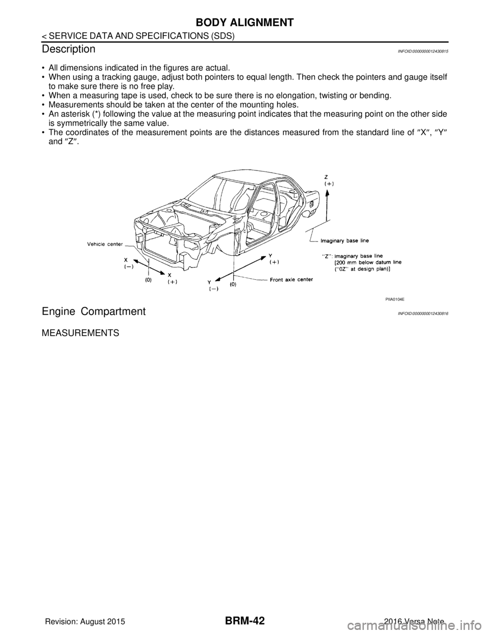
• All dimensions indicated in the figures are actual.
• When using a tracking gauge, adjust both pointers to equal length. Then check the pointers and gauge itself
to make sure there is no free play.
• When a measuring tape is used, check to be sure there is no elongation, twisting or bending.
• Measurements should be taken at the center of the mounting holes.
• An asterisk (*) following the value at the measuring point indicates that the measuring point on the other side
is symmetrically the same value.
• The coordinates of the measurement points are the distances measured from the standard line of ″ X″, ″Y ″
and ″Z ″.
Engine CompartmentINFOID:0000000012430816
MEASUREMENTS
PIIA0104E
Revision: August 2015 2016 Versa Note
cardiagn.com
Page 446 of 3641

BODY ALIGNMENTBRM-47
< SERVICE DATA AND SPECIFICATIONS (SDS)
C
DE
F
G H
I
J
L
M A
B
BRM
N
O P
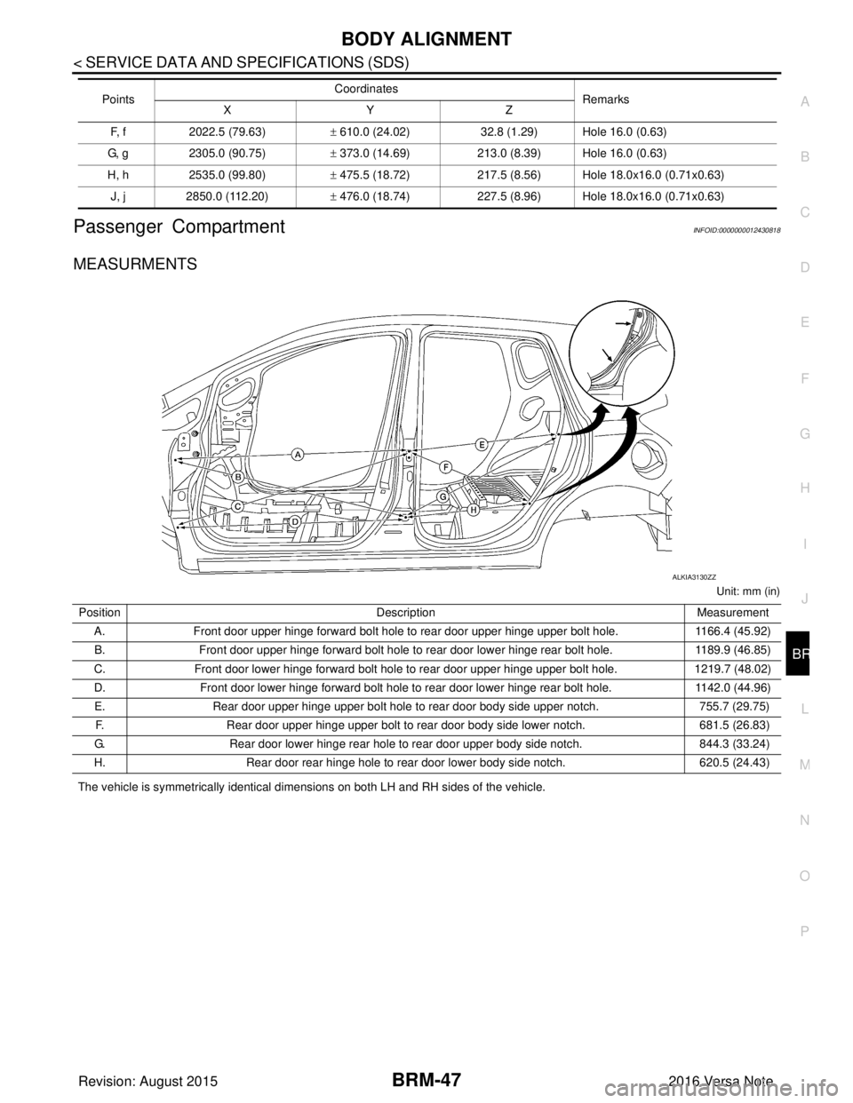
Passenger CompartmentINFOID:0000000012430818
MEASURMENTS
Unit: mm (in)
The vehicle is symmetrically identical dimensions on both LH and RH sides of the vehicle. F, f
2022.5 (79.63) ± 610.0 (24.02) 32.8 (1.29) Hole 16.0 (0.63)
G, g 2305.0 (90.75) ± 373.0 (14.69) 213.0 (8.39) Hole 16.0 (0.63)
H, h 2535.0 (99.80) ± 475.5 (18.72) 217.5 (8.56) Hole 18.0x16.0 (0.71x0.63)
J, j 2850.0 (112.20) ± 476.0 (18.74) 227.5 (8.96) Hole 18.0x16.0 (0.71x0.63)
Points
Coordinates
Remarks
XYZ
ALKIA3130ZZ
Position Description Measurement
A. Front door upper hinge forward bolt hole to rear door upper hinge upper bolt hole. 1166.4 (45.92)
B. Front door upper hinge forward bolt hole to rear door lower hinge rear bolt hole. 1189.9 (46.85)
C. Front door lower hinge forward bolt hole to rear door upper hinge upper bolt hole. 1219.7 (48.02)
D. Front door lower hinge forward bolt hole to rear door lower hinge rear bolt hole. 1142.0 (44.96)
E. Rear door upper hinge upper bolt hole to rear door body side upper notch. 755.7 (29.75)
F. Rear door upper hinge upper bolt to rear door body side lower notch. 681.5 (26.83)
G. Rear door lower hinge rear hole to rear door upper body side notch. 844.3 (33.24)
H. Rear door rear hinge hole to rear door lower body side notch. 620.5 (24.43)
Revision: August 2015 2016 Versa Note
cardiagn.com
Page 447 of 3641

BRM-48
< SERVICE DATA AND SPECIFICATIONS (SDS)
BODY ALIGNMENT
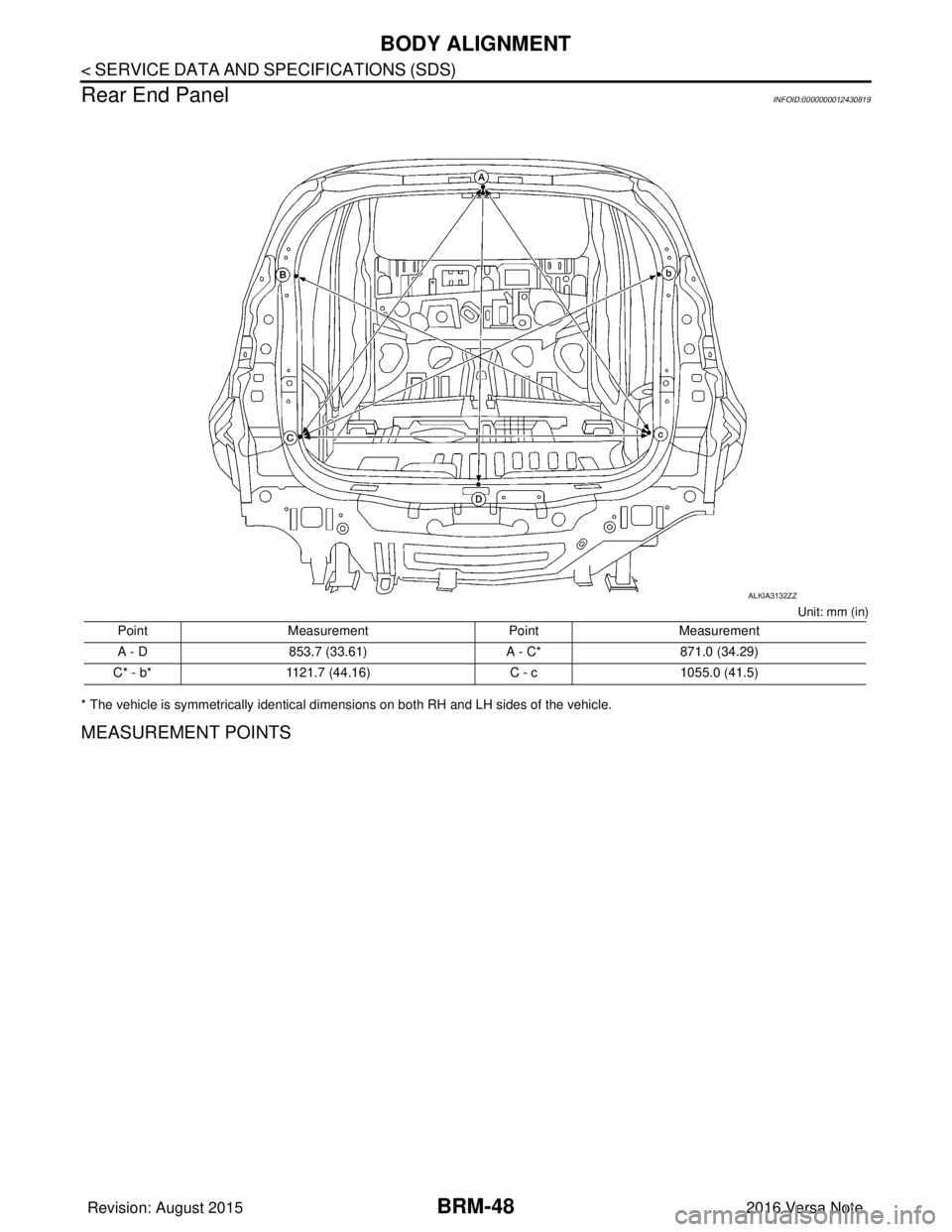
Rear End Panel
INFOID:0000000012430819
Unit: mm (in)
* The vehicle is symmetrically identical dimensions on both RH and LH sides of the vehicle.
MEASUREMENT POINTS
Point Measurement PointMeasurement
A - D 853.7 (33.61) A - C*871.0 (34.29)
C* - b* 1121.7 (44.16) C - c1055.0 (41.5)
ALKIA3132ZZ
Revision: August 2015 2016 Versa Note
cardiagn.com
Page 1006 of 3641
![NISSAN NOTE 2016 Service Repair Manual PRECAUTIONSEM-5
< PRECAUTION > [HR16DE]
C
D
E
F
G H
I
J
K L
M A
EM
NP
O
1. Using suitable tool (A), remove old liquid gasket adhering to the
liquid gasket application surface and the mating surface.
� NISSAN NOTE 2016 Service Repair Manual PRECAUTIONSEM-5
< PRECAUTION > [HR16DE]
C
D
E
F
G H
I
J
K L
M A
EM
NP
O
1. Using suitable tool (A), remove old liquid gasket adhering to the
liquid gasket application surface and the mating surface.
�](/manual-img/5/57363/w960_57363-1005.png)
PRECAUTIONSEM-5
< PRECAUTION > [HR16DE]
C
D
E
F
G H
I
J
K L
M A
EM
NP
O
1. Using suitable tool (A), remove old liquid gasket adhering to the
liquid gasket application surface and the mating surface.
• Remove liquid gasket completely from the groove of the liquidgasket application surface, mounting bolts, and bolt holes.
2. Thoroughly clean the gasket application surface and the mating surface and remove adhering moisture, grease and foreign
materials.
3. Attach liquid gasket tube to the suitable tool. Use Genuine Silicone RTV Sealant, or equivalent. Refer to
GI-22, "
Recommended Chemical Products and Sealants".
4. Apply liquid gasket without gaps to the specified location accord- ing to the specified dimensions.
• If there is a groove for liquid gasket application, apply liquid
gasket to the groove.
• As for bolt holes (B), normally apply liquid gasket inside the holes. Occasionally, it should be applied outside the holes.
Check to read the text of this manual.
• Within five minutes of liquid gasket application, install the mat- ing component.
• If liquid gasket protrudes, wipe it off immediately.
• Do not retighten mounting bolts or nuts after the installation.
• After 30 minutes or more have passed from the installation, fill engine oil and engine coolant.
CAUTION:
If there are specific instructions in the procedures contained in this manual concerning liquid gas-
ket application, observe them.
JPBIA0053ZZ
EMA0622D
(A) : Groove
: Inside
JPBIA0010ZZ
Revision: August 2015 2016 Versa Note
cardiagn.com
Page 1009 of 3641
![NISSAN NOTE 2016 Service Repair Manual EM-8
< PREPARATION >[HR16DE]
PREPARATION
Spark plug wrench
Removing and installing spark plug
a: 14 mm (0.55 in)
Pulley holder Crankshaft pulley removing and installing
Valve seat cutter set Finishing NISSAN NOTE 2016 Service Repair Manual EM-8
< PREPARATION >[HR16DE]
PREPARATION
Spark plug wrench
Removing and installing spark plug
a: 14 mm (0.55 in)
Pulley holder Crankshaft pulley removing and installing
Valve seat cutter set Finishing](/manual-img/5/57363/w960_57363-1008.png)
EM-8
< PREPARATION >[HR16DE]
PREPARATION
Spark plug wrench
Removing and installing spark plug
a: 14 mm (0.55 in)
Pulley holder Crankshaft pulley removing and installing
Valve seat cutter set Finishing valve seat dimensions
Piston ring expander Removing and installing piston ring
Valve guide drift Removing and installing valve guide
Valve guide reamer (1): Reaming valve guide inner hole
(2): Reaming hole for oversize valve guide
(J-43897-18)
(J-43897-12)
Oxygen sensor thread cleaner Reconditioning the exhaust system threads
before installing a new air fuel ratio sensor
(Use with anti-seize lubricant shown below.)
A: [18 mm (0.71 in) dia.] for zirconia heated
oxygen sensor
B: [12 mm (0.47 in) dia.] for titania heated
oxygen sensor
C: Mating surface shave cylinder
D: Flutes
Tool name
Description
JPBIA0399ZZ
NT035
S-NT048
S-NT030
PBIC4012E
PBIC4013E
JPBIA0238ZZ
Revision: August 2015 2016 Versa Note
cardiagn.com
Page 1040 of 3641
![NISSAN NOTE 2016 Service Repair Manual OIL PAN AND OIL STRAINEREM-39
< REMOVAL AND INSTALLATION > [HR16DE]
C
D
E
F
G H
I
J
K L
M A
EM
NP
O
c. Press-fit the rear oil seal using a suitable drift (A) with outer
diameter 113 mm (4.45 in) and i NISSAN NOTE 2016 Service Repair Manual OIL PAN AND OIL STRAINEREM-39
< REMOVAL AND INSTALLATION > [HR16DE]
C
D
E
F
G H
I
J
K L
M A
EM
NP
O
c. Press-fit the rear oil seal using a suitable drift (A) with outer
diameter 113 mm (4.45 in) and i](/manual-img/5/57363/w960_57363-1039.png)
OIL PAN AND OIL STRAINEREM-39
< REMOVAL AND INSTALLATION > [HR16DE]
C
D
E
F
G H
I
J
K L
M A
EM
NP
O
c. Press-fit the rear oil seal using a suitable drift (A) with outer
diameter 113 mm (4.45 in) and inner diameter 90 mm (3.54 in).
• Press-fit to the specified dimensions as shown.
CAUTION:
• Do not touch the grease applied to the oil seal lip.
• Be careful not to damage the rear oil seal mounting partof oil pan (upper) and cylinder block or the crankshaft.
• Press-fit straight and check that oil seal does not curl or tilt.
d. After press-fitting the rear oil seal, completely wipe off any liquid gasket protruding to rear end surface side.
3. Installation of the remaining components is in the reverse order of removal.
INSPECTION AFTER INSTALLATION
• Before starting engine, check oil/fluid levels, includi ng engine coolant and engine oil. If less than required
quantity, fill to the specified level. Refer to MA-11, "
Fluids and Lubricants".
• Use procedure below to check for fuel leakage.
• Turn ignition switch ON (with engine stopped). With fuel pressure applied to fuel piping, check for fuel leak- age at connection points.
• Start engine. With engine speed increased, check again for fuel leakage at connection points.
• Run engine to check for unusual noise and vibration. NOTE:
If hydraulic pressure inside timing chain tensioner drops after removal and installation, slack in the guide
may generate a pounding noise during and just after engine start. However, this is normal. Noise will stop
after hydraulic pressure rises.
• Warm up engine thoroughly to make sure there is no leakage of fuel, exhaust gas, or any oils/fluids including engine oil and engine coolant.
• Bleed air from passages in lines and hoses, such as in cooling system.
• After cooling down engine, again check oil/fluid levels including engine oil and engine coolant. Refill to spec- ified level, if necessary.
• Summary of the inspection items:
*Power steering fluid, brake fluid, etc.
PBIC3660E
(1) : Rear oil seal
(A) : Rear end surface of cylinder block
PBIC3149J
Item Before starting engine Engine runningAfter engine stopped
Engine coolant LevelLeakage Level
Engine oil LevelLeakage Level
Transmission/
transaxle fluid A/T and CVT Models
LeakageLevel/Leakage Leakage
M/T Models Level/Leakage LeakageLevel/Leakage
Other oils and fluids* LevelLeakage Level
Fuel LeakageLeakageLeakage
Exhaust gas —Leakage —
Revision: August 2015 2016 Versa Note
cardiagn.com
Page 1082 of 3641
![NISSAN NOTE 2016 Service Repair Manual CYLINDER HEADEM-81
< REMOVAL AND INSTALLATION > [HR16DE]
C
D
E
F
G H
I
J
K L
M A
EM
NP
O
2. At each of several locations on bottom surface of cylinder head,
measure the distortion in six directions us NISSAN NOTE 2016 Service Repair Manual CYLINDER HEADEM-81
< REMOVAL AND INSTALLATION > [HR16DE]
C
D
E
F
G H
I
J
K L
M A
EM
NP
O
2. At each of several locations on bottom surface of cylinder head,
measure the distortion in six directions us](/manual-img/5/57363/w960_57363-1081.png)
CYLINDER HEADEM-81
< REMOVAL AND INSTALLATION > [HR16DE]
C
D
E
F
G H
I
J
K L
M A
EM
NP
O
2. At each of several locations on bottom surface of cylinder head,
measure the distortion in six directions using suitable tools (A/
B).
• If it exceeds the limit, replace cylinder head.
INSPECTION AFTER DISASSEMBLY
VALVE DIMENSIONS
• Check the dimensions of each valv e. For the dimensions, refer to EM-119, "Cylinder head".
• If dimensions are out of the standard, replace valv e and check valve seat contact. Refer to “VALVE SEAT
CONTACT”.
VALVE GUIDE CLEARANCE
Valve Stem Diameter• Measure the diameter of valve stem using suitable tool (A).
Valve Guide Inner Diameter• Measure the inner diameter of valve guide using suitable tool (A).
Valve Guide Clearance• (Valve guide clearance) = (Valve guide inner diameter) – (Valve stem diameter)
• If the calculated value exceeds the limit, replace valve and/or valve guide. Refer to EM-78, "
Disassembly
and Assembly".
VALVE GUIDE REPLACEMENT
When valve guide is removed, replace with oversized [0.2 mm (0.008 in)] valve guide.
1. To remove valve guide, heat cylinder head to 110 to 130°C (230
to 266 °F) by soaking in heated oil.
Limit : Refer to
EM-119, "
Cylinder head".
PBIC3207J
Standard : Refer to EM-119, "Cylinder head".
Standard : Refer to EM-119, "
Cylinder head".
Standard and Limit : Refer to EM-119, "
Cylinder head".
PBIC3213J
SEM008A
Revision: August 2015 2016 Versa Note
cardiagn.com