2016 NISSAN NOTE dimensions
[x] Cancel search: dimensionsPage 1614 of 3641
![NISSAN NOTE 2016 Service Repair Manual ENGINE COOLANTCO-9
< PERIODIC MAINTENANCE > [HR16DE]
C
D
E
F
G H
I
J
K L
M A
CO
NP
O
2. Connect a suitable hose to the radiator drain plug.
• Use a suitable hose with the dimensions as shown.
3. Ope NISSAN NOTE 2016 Service Repair Manual ENGINE COOLANTCO-9
< PERIODIC MAINTENANCE > [HR16DE]
C
D
E
F
G H
I
J
K L
M A
CO
NP
O
2. Connect a suitable hose to the radiator drain plug.
• Use a suitable hose with the dimensions as shown.
3. Ope](/manual-img/5/57363/w960_57363-1613.png)
ENGINE COOLANTCO-9
< PERIODIC MAINTENANCE > [HR16DE]
C
D
E
F
G H
I
J
K L
M A
CO
NP
O
2. Connect a suitable hose to the radiator drain plug.
• Use a suitable hose with the dimensions as shown.
3. Open radiator drain plug (A) at the bottom of radiator, and then remove radiator cap.
(B): Suitable hose
: Front
CAUTION:
• Perform this step when engine is cold.
• Do not spill engine coolant on the drive belt.
4. It is necessary to drain the cylinder block when drai ning all of engine coolant in the system. To drain the
cylinder block, open the water drain plugs on cylinder block. Refer to EM-93, "
Exploded View".
5. Remove reservoir tank if necessary, and drain engine coolant and clean reservoir tank before installing. Refer to CO-13, "
Exploded View".
6. Check drained engine coolant for contaminants such as rust, corrosion or discoloration. If contaminated,
flush the engine cooling system. Refer to CO-11, "
Flushing Cooling System".
RefillingINFOID:0000000012432135
1. Install the radiator drain plug. Install the reservoir tank and cylinder block drain plug, if removed for a total
system drain or for engine removal or repair.
• The radiator must be completely empty of engine coolant and water.
• Apply sealant to the threads of the cylinder block drain plug. Use Genuine High Performance
Thread Sealant or equivalent. Refer to MA-11, "
Fluids and Lubricants".
2. If disconnected, reattach the upper radiator hose at the engine side.
3. Set the vehicle heater controls to the full HOT and heat er ON position. Turn the vehicle ignition ON with
the engine OFF as necessary to activate the heater mode. Diameter (A) : 0.8 mm (0.31 in)
Length (B) : 300 mm (11.81 in)
JPBIA4770ZZ
AWBIA1613ZZ
Radiator drain plug : Refer to CO-13, "Exploded View".
Revision: August 2015
2016 Versa Note
cardiagn.com
Page 1633 of 3641
![NISSAN NOTE 2016 Service Repair Manual PRECAUTIONSLU-3
< PRECAUTION > [HR16DE]
C
D
E
F
G H
I
J
K L
M A
LU
NP
O
3. Attach liquid gasket tube to the suitable tool.
Use Genuine Silicone RTV Sealant, or equivalent. Refer to
GI-22, "
Recommend NISSAN NOTE 2016 Service Repair Manual PRECAUTIONSLU-3
< PRECAUTION > [HR16DE]
C
D
E
F
G H
I
J
K L
M A
LU
NP
O
3. Attach liquid gasket tube to the suitable tool.
Use Genuine Silicone RTV Sealant, or equivalent. Refer to
GI-22, "
Recommend](/manual-img/5/57363/w960_57363-1632.png)
PRECAUTIONSLU-3
< PRECAUTION > [HR16DE]
C
D
E
F
G H
I
J
K L
M A
LU
NP
O
3. Attach liquid gasket tube to the suitable tool.
Use Genuine Silicone RTV Sealant, or equivalent. Refer to
GI-22, "
Recommended Chemical Products and Sealants".
4. Apply liquid gasket without gaps to the specified location accord- ing to the specified dimensions.
• If there is a groove for liquid gasket application, apply liquidgasket to the groove.
• As for bolt holes (B), normally apply liquid gasket inside the holes. Occasionally, it should be applied outside the holes.
Check to read the text of this manual.
• Within five minutes of liquid gasket application, install the mat- ing component.
• If liquid gasket protrudes, wipe it off immediately.
• Do not retighten mounting bolts or nuts after the installation.
• After 30 minutes or more have passed from the installation, fill engine oil and engine coolant.
CAUTION:
If there are specific instructions in the procedures contained in this manual concerning liquid gasket
application, observe them.
EMA0622D
(A) : Groove
: Inside
JPBIA0010ZZ
Revision: August 2015 2016 Versa Note
cardiagn.com
Page 1750 of 3641

EXL-98
< PERIODIC MAINTENANCE >
HEADLAMP AIMING ADJUSTMENT
Aiming Adjustment Procedure
INFOID:0000000012432829
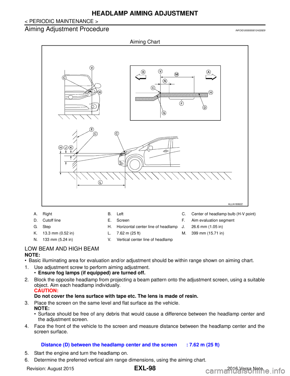
Aiming Chart
LOW BEAM AND HIGH BEAM
NOTE:
• Basic illuminating area for evaluation and/or adjus tment should be within range shown on aiming chart.
1. Use adjustment screw to perform aiming adjustment. •Ensure fog lamps (if eq uipped) are turned off.
2. Block the opposite headlamp from projecting a beam pa ttern onto the adjustment screen, using a suitable
object. Aim each headlamp individually.
CAUTION:
Do not cover the lens surface with tape etc. The lens is made of resin.
3. Place the screen on the same level and flat surface as the vehicle. NOTE:
• Surface should be free of any debris that would cause a difference between the headlamp center and
the adjustment screen.
4. Face the front of the vehicle to the screen and measure distance between the headlamp center and the screen surface.
5. Start the engine and turn the headlamp on.
6. Determine the preferred vertical aim range dimensions, using the aiming chart.
ALLIA1808ZZ
A. Right B. LeftC. Center of headlamp bulb (H-V point)
D. Cutoff line E. ScreenF. Aim evaluation segment
G. Step H. Horizontal center line of headlamp J. 26.6 mm (1.05 in)
K. 13.3 mm (0.52 in) L. 7.62 m (25 ft)M. 399 mm (15.71 in)
N. 133 mm (5.24 in) V. Vertical center line of headlamp
Distance (D) between the headlamp center and the screen : 7.62 m (25 ft)
Revision: August 2015 2016 Versa Note
cardiagn.com
Page 1751 of 3641

HEADLAMP AIMING ADJUSTMENTEXL-99
< PERIODIC MAINTENANCE >
C
DE
F
G H
I
J
K
M A
B
EXL
N
O P
7. Measure the projected beam within t he aim evaluation segment on the screen.
8. Adjust the beam pattern of each headlamp until the ai m evaluation segment (the area relative to both the
highest and lowest cutoff line height) is positioned within the vertical aim range dimensions shown on the
aiming chart.
Revision: August 2015 2016 Versa Note
cardiagn.com
Page 1889 of 3641

GI-1
GENERAL INFORMATION
C
DE
F
G H
I
J
K L
M B
GI
SECTION GI
N
O P
CONTENTS
GENERAL INFORMATION
HOW TO USE THIS MANU AL ......................3
HOW TO USE THIS MANUAL ....................... .....3
Description .......................................................... ......3
Terms ........................................................................3
Units ..........................................................................3
Contents ....................................................................3
Relation between Illustrations and Descriptions .......4
Components ..............................................................4
HOW TO FOLLOW TROUBLE DIAGNOSES .....6
Description ................................................................6
How to Follow Test Groups in Trouble Diagnosis ......6
Key to Symbols Signifying Measurements or Pro-
cedures ............................................................... ......
7
HOW TO READ WIRING DIAGRAMS ................9
Connector Symbols ............................................. ......9
Sample/Wiring Diagram -Example- .........................10
Connector Information .............................................12
ABBREVIATIONS .......................................... ....14
Abbreviation List .................................................. ....14
TIGHTENING TORQUE OF STANDARD
BOLTS ................................................................
19
Description .......................................................... ....19
Tightening Torque Table (New Standard Includ-
ed) ...........................................................................
19
RECOMMENDED CHEMICAL PRODUCTS
AND SEALANTS ................................................
22
Recommended Chemical Products and Sealants ....22
PRECAUTION ..............................................23
PRECAUTIONS .............................................. ....23
Description .......................................................... ....23
Precaution for Supplemental Restraint System
(SRS) "AIR BAG" and "SEAT BELT PRE-TEN-
SIONER" .................................................................
23
Procedures without Cowl Top Cover .......................23
Cautions in Removing Battery Terminal and AV
Control Unit (Models with AV Control Unit) .............
23
General Precautions ............................................ ....24
Three Way Catalyst .................................................25
Fuel ..........................................................................25
Multiport Fuel Injection System or Engine Control
System .....................................................................
26
Hoses ......................................................................26
Engine Oils ..............................................................27
Air Conditioning .......................................................27
LIFTING POINT .................................................28
Special Service Tool ................................................28
Garage Jack and Safety Stand ................................28
2-Pole Lift ................................................................29
Board-on Lift ............................................................30
TOW TRUCK TOWING .....................................31
Tow Truck Towing ...................................................31
Vehicle Recovery (Freeing a Stuck Vehicle) ...........31
VEHICLE INFORMATION ...........................33
IDENTIFICATION INFORMATION ....................33
Model Variation .................................................... ....33
Identification Number ...............................................34
Identification Plate ...................................................35
Engine Serial Number .............................................36
CVT Number ............................................................36
Manual Transaxle Number ......................................36
Dimensions ..............................................................36
Wheels & Tires ........................................................37
BASIC INSPECTION ...................................38
SERVICE INFORMATION FOR ELECTRICAL
INCIDENT ..........................................................
38
Work Flow ............................................................ ....38
Control Units and Electrical Parts ............................38
How to Check Terminal ...........................................39
Intermittent Incident ............................................. ....42
Circuit Inspection .....................................................44
Revision: August 2015 2016 Versa Note
cardiagn.com
Page 1924 of 3641

GI-36
< VEHICLE INFORMATION >
IDENTIFICATION INFORMATION
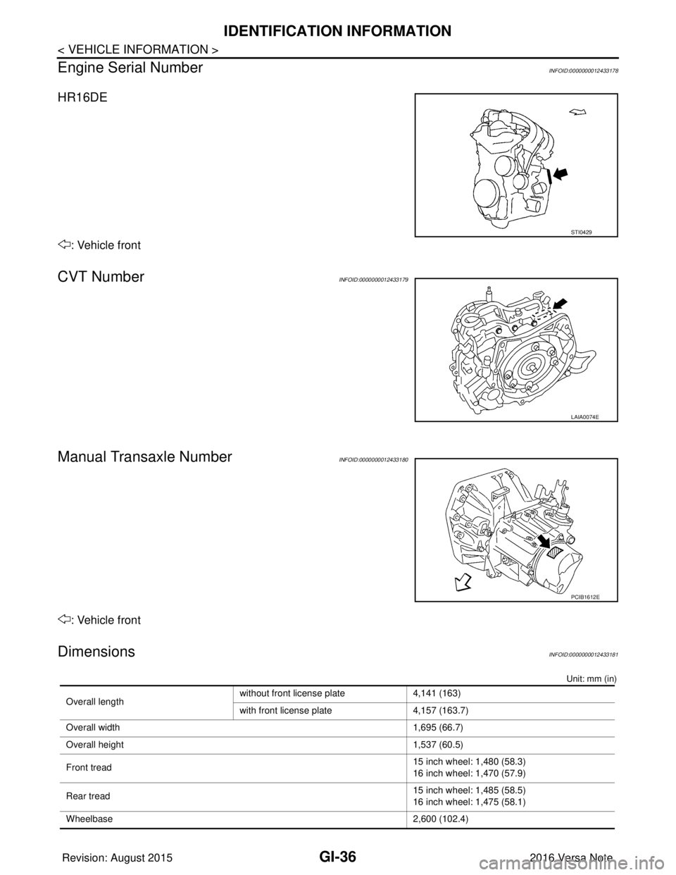
Engine Serial Number
INFOID:0000000012433178
HR16DE
: Vehicle front
CVT NumberINFOID:0000000012433179
Manual Transaxle NumberINFOID:0000000012433180
: Vehicle front
DimensionsINFOID:0000000012433181
Unit: mm (in)
STI0429
LAIA0074E
PCIB1612E
Overall length without front license plate 4,141 (163)
with front license plate
4,157 (163.7)
Overall width 1,695 (66.7)
Overall height 1,537 (60.5)
Front tread 15 inch wheel: 1,480 (58.3)
16 inch wheel: 1,470 (57.9)
Rear tread 15 inch wheel: 1,485 (58.5)
16 inch wheel: 1,475 (58.1)
Wheelbase 2,600 (102.4)
Revision: August 2015 2016 Versa Note
cardiagn.com
Page 2331 of 3641

MA-16
< PERIODIC MAINTENANCE >
ENGINE MAINTENANCE
ENGINE COOLANT : Draining Engine Coolant
INFOID:0000000012432253
WARNING:
Do not remove the radiator cap when the engine is hot. Serious burns could occur from high-pressure
engine coolant escaping from the radiator. Wrap a th ick cloth around the cap. Slowly push down and
turn it a quarter turn to allow built-up pressure to escape. Carefully remove the cap by pushing it down
and turning it all the way.
1. Remove front under cover. Refer to EXT-39, "
FRONT UNDER COVER : Removal and Installation".
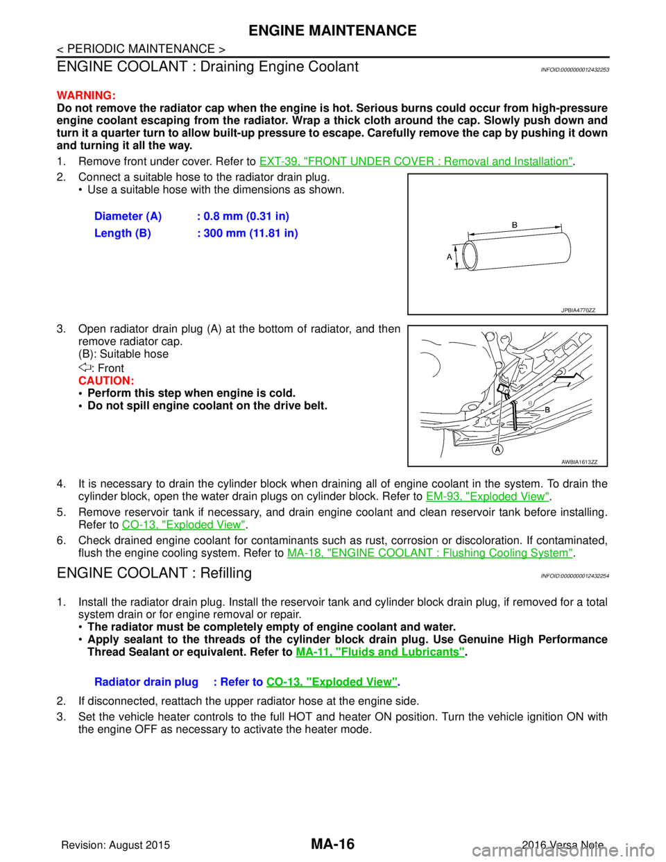
2. Connect a suitable hose to the radiator drain plug. • Use a suitable hose with the dimensions as shown.
3. Open radiator drain plug (A) at the bottom of radiator, and then remove radiator cap.
(B): Suitable hose
: Front
CAUTION:
• Perform this step when engine is cold.
• Do not spill engine coolant on the drive belt.
4. It is necessary to drain the cylinder block when drai ning all of engine coolant in the system. To drain the
cylinder block, open the water drain plugs on cylinder block. Refer to EM-93, "
Exploded View".
5. Remove reservoir tank if necessary, and drain engine coolant and clean reservoir tank before installing. Refer to CO-13, "
Exploded View".
6. Check drained engine coolant for contaminants such as rust, corrosion or discoloration. If contaminated, flush the engine cooling system. Refer to MA-18, "
ENGINE COOLANT : Flushing Cooling System".
ENGINE COOLANT : RefillingINFOID:0000000012432254
1. Install the radiator drain plug. Install the reservoir tank and cylinder block drain plug, if removed for a total
system drain or for engine removal or repair.
• The radiator must be completely empty of engine coolant and water.
• Apply sealant to the threads of the cylinder block drain plug. Use Genuine High Performance
Thread Sealant or equivalent. Refer to MA-11, "
Fluids and Lubricants".
2. If disconnected, reattach the upper radiator hose at the engine side.
3. Set the vehicle heater controls to the full HOT and heat er ON position. Turn the vehicle ignition ON with
the engine OFF as necessary to activate the heater mode. Diameter (A) : 0.8 mm (0.31 in)
Length (B) : 300 mm (11.81 in)
JPBIA4770ZZ
AWBIA1613ZZ
Radiator drain plug : Refer to
CO-13, "Exploded View".
Revision: August 2015 2016 Versa Note
cardiagn.com
Page 3249 of 3641
![NISSAN NOTE 2016 Service Repair Manual TM-8
< PRECAUTION >[5MT: RS5F91R]
PRECAUTIONS
- Oily dirt:
• Dip a soft cloth into lukewarm water with mild detergent (concentration: within 2 to 3%) and wipe the dirty
area.
• Then dip a cloth in NISSAN NOTE 2016 Service Repair Manual TM-8
< PRECAUTION >[5MT: RS5F91R]
PRECAUTIONS
- Oily dirt:
• Dip a soft cloth into lukewarm water with mild detergent (concentration: within 2 to 3%) and wipe the dirty
area.
• Then dip a cloth in](/manual-img/5/57363/w960_57363-3248.png)
TM-8
< PRECAUTION >[5MT: RS5F91R]
PRECAUTIONS
- Oily dirt:
• Dip a soft cloth into lukewarm water with mild detergent (concentration: within 2 to 3%) and wipe the dirty
area.
• Then dip a cloth into fresh water, wring the water out of the cloth and wipe the detergent off.
• Then rub with a soft, dry cloth.
- Do not use organic solvent such as thinner, benzene, alcohol or gasoline.
- For genuine leather seats, use a genuine leather seat cleaner.
Liquid GasketINFOID:0000000012430939
REMOVAL OF LIQUID GASKET SEALING
• After removing the bolts and nuts, separate the mating surface and remove the liquid gasket using Tool (A).
CAUTION:
Be careful not to damage the mating surfaces.
• In areas where the cutter is difficult to use, use a plastic hammer to lightly tap (1) the cutter where the liquid gasket is applied. Use a
plastic hammer to slide (2) the cutter by tapping on the side.
CAUTION:
Do not damage the mating surfaces.
LIQUID GASKET APPLICATION PROCEDURE
1. Using suitable tool (A), remove old liquid gasket adhering to the liquid gasket application surface and the mating surface.
• Remove liquid gasket completely from the groove of the liquidgasket application surface, mounting bolts, and bolt holes.
2. Wipe the liquid gasket application surface and the mating sur- face with white gasoline (lighting and heating use) to remove
adhering moisture, grease and foreign materials.
3. Attach liquid gasket tube to the suitable tool. Use Genuine Silicone RTV Seal ant, or equivalent. Refer to
GI-22, "
Recommended Chemical Products and Sealants".
4. Apply liquid gasket without gaps to the specified location accord- ing to the specified dimensions.
• If there is a groove for liquid gasket application, apply liquid
gasket to the groove.
• As for bolt holes (B), normally apply liquid gasket inside the holes. Occasionally, it should be applied outside the holes.
Check to read the text of this manual.
• Within five minutes of liquid gasket application, install the mat- ing component.
• If liquid gasket protrudes, wipe it off immediately.
• Do not retighten mounting bolts or nuts after the installation. Tool Number : KV10111100 (J-37228)
AWBIA1249GB
JPBIA0053ZZ
EMA0622D
(A) : Groove
: Inside
JPBIA0010ZZ
Revision: August 2015 2016 Versa Note
cardiagn.com