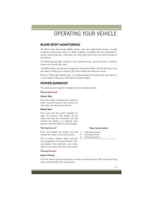
Page 249 of 276
WARNING!
• You can be badly injured working on or around a motor vehicle. Do only service work for which you have the knowledge and theright equipment. If you have any doubt about your ability to perform a service job, take your vehicle to a competent mechanic.
• Failure to properly inspect and maintain your vehicle could result in a component malfunction and effect vehicle handling and
performance. This could cause an accident.
MAINTAINING YOUR VEHICLE
247
Page 250 of 276
MAINTENANCE RECORD
Odometer Date Signature, Autho-rized Service Center
10,000 Miles
(16,000 km) or
1 Years
20,000 Miles
(32,000 km) or
2 Years
30,000 Miles
(48,000 km) or
3 Years
40,000 Miles
(64,000 km) or
4 Years
50,000 Miles
(80,000 km) or
5 Years
60,000 Miles
(96,000 km) or
6 Years
70,000 Miles
(112,000 km) or
7 Years
80,000 Miles
(128,000 km) or
8 Years
Odometer Date Signature, Autho- rized Service Center
90,000 Miles
(144,000 km) or
9 Years
100,000 Miles
(160,000 km) or
10 Years
110,000 Miles
(176,000 km) or
11 Years
120,000 Miles
(192,000 km) or
12 Years
130,000 Miles
(208,000 km) or
13 Years
140,000 Miles
(224,000 km) or
14 Years
150,000 Miles
(240,000 km) or
15 Years
MAINTAINING YOUR VEHICLE
248
Page 251 of 276

FUSES
Power Distribution Center
The Power Distribution Center is located in the engine compartment near the battery.
This center contains cartridge fuses, micro fuses, relays, and circuit breakers. A
description of each fuse and component may be stamped on the inside cover,
otherwise the cavity number of each fuse is stamped on the inside cover that
corresponds to the following chart.
Cavity Cartridge Fuse Micro FuseDescription
F03 60 Amp Yellow – Radiator Fan
F05 40 Amp Green – Compressor for Air Suspension - If Equipped
F06 40 Amp Green – Anti-lock Brakes/Electronic Sta- bility Control Pump
F07 30 Amp Pink – Starter Solenoid
F09 30 Amp Pink – Diesel Fuel Heater (Diesel en- gine only) / Brake Vacuum Pump
F10 40 Amp Green – Body Controller / Exterior Light- ing #2
F11 30 Amp Pink – Trailer Tow Electric Brake - If Equipped
F12 40 Amp Green – Body Controller #3 / Power
Locks
F13 40 Amp Green – Blower Motor Front
F14 40 Amp Green – Body Controller #4 / Exterior
Lighting #1
F17 30 Amp Pink – Headlamp Washer- If Equipped
F19 20 Amp Blue – Headrest Solenoid- If Equipped
F20 30 Amp Pink – Passenger Door Module
F22 20 Amp Blue – Engine Control Module
F23 30 Amp Pink – Interior Lights #1
F24 30 Amp Pink – Driver Door Module
F25 30 Amp Pink – Front Wipers
F26 30 Amp Pink – Anti-lock Brakes/Stability Con- trol Module/Valves
F28 20 Amp Blue – Trailer Tow Backup Lights - If Equipped
F29 20 Amp Blue – Trailer Tow Parking Lights - If Equipped
F30 30 Amp Pink – Trailer Tow Receptacle - If
Equipped
F32 30 Amp Pink – Drive Train Control Module
F34 30 Amp Pink – Slip Differential Control
MAINTAINING YOUR VEHICLE
249
Page 252 of 276

Cavity Cartridge Fuse Micro FuseDescription
F35 30 Amp Pink – Sunroof - If Equipped
F36 30 Amp Pink – Rear Defroster
F37 25 Amp Clear – Rear Blower Motor - If Equipped
F38 30 Amp Pink – Power Inverter 115V AC - If
Equipped
F39 30 Amp Pink – Power Liftgate - If Equipped
F40 – 10 Amp Red Daytime Running Lights/
Headlamp Leveling
F42 – 20 Amp Yellow Horn
F44 – 10 Amp Red Diagnostic Port
F49 – 10 Amp Red Integrated Central Stack / Cli-
mate Control
F50 – 20 Amp Yellow Air Suspension Control Module -
If Equipped
F51 – 15 Amp Blue Ignition Node Module / Keyless
Ignition / Steering Column Lock
F52 –5 Amp Tan Battery Sensor
F53 – 20 Amp Yellow Trailer Tow – Left Turn/Stop
Lights - If Equipped
F56 – 15 Amp Blue Additional Content (Diesel en-
gine only)
F57 – 20 Amp Yellow NOX Sensor
F58 – 15 Amp Blue HID Headlamps LH - If
Equipped
F59 – 10 Amp Red Purging Pump (Diesel engine
only)
F60 – 15 Amp Blue Transmission Control Module
F61 – 10 Amp Red Transmission Control Module/PM
Sensor (Diesel engine only)
F62 – 10 Amp Red Air Conditioning Clutch
F63 – 20 Amp Yellow Ignition Coils (Gas), Urea Heater
(Diesel)
F64 – 25 Amp Clear Fuel Injectors / Powertrain
F66 – 10 Amp Red Sunroof / Passenger Window
Switches / Rain Sensor
F67 – 15 Amp Blue CD / DVD / Bluetooth Hands-free
Module - If Equipped
F68 – 20 Amp Yellow Rear Wiper Motor
F69 – 15 Amp Blue Spotlight Feed - If Equipped
F70 – 20 Amp Yellow Fuel Pump Motor
F71 – 30 Amp Green Audio Amplifier
F72 – 10 Amp Red PCM (If Equipped)
MAINTAINING YOUR VEHICLE
250
Page 253 of 276

Cavity Cartridge Fuse Micro FuseDescription
F73 – 15 Amp Blue HID Headlamp RH - If Equipped
F75 – 10 Amp Red Dual Batt Control (If Equipped)
F76 – 10 Amp Red Anti-lock Brakes/Electronic Sta-
bility Control
F77 – 10 Amp Red Drivetrain Control Module/Front
Axle Disconnect Module
F78 – 10 Amp Red Engine Control Module / Electric
Power Steering
F80 – 10 Amp Red Universal Garage Door Opener /
Compass / Anti-Intrusion Module
F81 – 20 Amp Yellow Trailer Tow Right Turn/Stop
Lights
F82 – 10 Amp Red Steering Column Control
Module/ Cruise Control / DTV
F83 – 10 Amp Red Fuel Door
F84 – 15 Amp Blue Switch Bank/Instrument Cluster
F85 – 10 Amp Red Airbag Module
F86 – 10 Amp Red Airbag Module
F87 – 10 Amp Red Air Suspension – If Equipped /
Trailer Tow / Steering ColumnControl Module
F88 – 15 Amp Blue Instrument Panel Cluster
F90/F91 – 20 Amp Yellow Power Outlet (Rear seats) Se-
lectable
F92 – 10 Amp Red Rear Console Lamp - If
Equipped
F93 – 20 Amp Yellow Cigar Lighter
F94 – 10 Amp Red Shifter / Transfer Case Module
F95 – 10 Amp Red Rear Camera / ParkSense
F96 – 10 Amp Red Rear Seat Heater Switch / Flash-
lamp Charger - If Equipped
F97 – 20 Amp Yellow Rear Heated Seats & Heated
Steering Wheel - If Equipped
F98 – 20 Amp Yellow
Front Heated Seats - If Equipped
F99– 10 Amp Red Climate Control / Driver Assis-
tance Systems Module / DSRC
F100 – 10 Amp Red Active Damping - If Equipped
F101 – 15 Amp Blue Electrochromatic Mirror/Smart
High Beams - If Equipped
F103 – 10 Amp Red Cabin Heater (Diesel Engine
Only)/Rear HVAC
F104 – 20 Amp Yellow Power Outlets (Instrument
Panel/Center Console)
MAINTAINING YOUR VEHICLE
251
Page 254 of 276

CAUTION!
• When installing the power distribution center cover, it is important to ensurethe cover is properly positioned and fully latched. Failure to do so may allow
water to get into the power distribution center and possibly result in an
electrical system failure.
• When replacing a blown fuse, it is important to use only a fuse having the
correct amperage rating. The use of a fuse with a rating other than indicated
may result in a dangerous electrical system overload. If a properly rated fuse
continues to blow, it indicates a problem in the circuit that must be corrected.
TIRE PRESSURES
Check the inflation pressure of each tire, including the spare tire (if equipped), at
least monthly and inflate to the recommended pressure for your vehicle.
The tire pressures recommended for your vehicle are found on the “Tire and Loading
Information” label located on the driver’s side door opening or B-Pillar.
NOTE:
Refer to the Owner's Manual on the DVD
or the Tire Information Supplement lo-
cated in your Owner’s Information kit for
more information regarding tire warnings
and instructions.
Tire And Loading Information Location (Example)
MAINTAINING YOUR VEHICLE
252
Page 255 of 276
WARNING!
• Overloading of your tires is dangerous. Overloading can cause tire failure,affect vehicle handling, and increase your stopping distance. Use tires of the
recommended load capacity for your vehicle. Never overload them.
• Improperly inflated tires are dangerous and can cause collisions. Under-
inflation increases tire flexing and can result in over-heating and tire failure.
Over-inflation reduces a tire’s ability to cushion shock. Objects on the road and
chuck holes can cause damage that results in tire failure. Unequal tire
pressures can cause steering problems. You could lose control of your vehicle.
Over-inflated or under-inflated tires can affect vehicle handling and can fail
suddenly, resulting in loss of vehicle control. Always drive with each tire
inflated to the recommended cold tire inflation pressure.
ADDING FUEL
1. Push the fuel filler door release switch (located under the headlamp switch).
Fuel Filler Door Release
MAINTAINING YOUR VEHICLE
253
Page 256 of 276

2. Open the fuel filler door.
NOTE:
In certain cold conditions, ice may pre-
vent the fuel door from opening. If this
occurs, lightly push on the fuel door to
break the ice buildup and re-release the
fuel door using the inside release button.
Do not pry on the door.
3. There is no fuel filler cap. A flapperdoor inside the pipe seals the system.
4. Insert the fuel nozzle fully into the filler pipe, the nozzle opens and holds
the flapper door while refueling.
5. Fill the vehicle with fuel, when the fuel nozzle “clicks” or shuts off the
fuel tank is full.
6. Remove the fuel nozzle and close the fuel door.
Fuel Door Emergency Release
• To manually open the fuel door, re- move the storage bin located in the
rear cargo area and pull the release
cable located in the storage bin
opening.
Storage Bin Removal
1. Push down on inboard edge. This will
pop up the outboard edge.
2. Grab popped up outboard edge with other hand to disengage snaps.
3. Remove storage bin.
Fuel Filler
Storage Bin Location
MAINTAINING YOUR VEHICLE
254