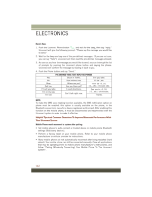
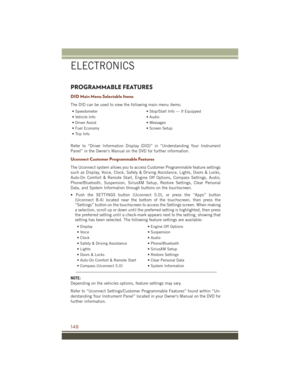
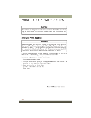
Page 153 of 276

2. Place the hand-held transmitter 1 to 3 inches (3 to 8 cm) away from theHomeLink button you wish to program while keeping the HomeLink indicator light
in view.
3. Push and hold the HomeLink button you want to program while you push and hold the hand-held transmitter button.
4. Continue to hold both buttons and observe the indicator light. The HomeLink indicator will flash slowly and then rapidly after HomeLink has received the
frequency signal from the hand-held transmitter. Release both buttons after the
indicator light changes from slow to rapid.
5. At the garage door opener motor (in the garage), locate the “LEARN” or “TRAINING” button. This can usually be found where the hanging antenna wire
is attached to the garage door opener motor. Firmly push and release the
“LEARN” or “TRAINING” button.
NOTE:
You have 30 seconds in which to initiate the next step after the LEARN button has
been pushed.
6. Return to the vehicle and push the programmed HomeLink button twice (holding the button for two seconds each time). If the device is plugged in and activates,
programming is complete.
NOTE:
If the device does not activate, push the button a third time (for two seconds) to
complete the training.
7. To program the remaining two HomeLink buttons, repeat each step for each remaining button. DO NOT erase the channels.
Programming A Non-Rolling Code
NOTE:
For programming Garage Door Openers manufactured before 1995.
1. Place the ignition switch to the ON/RUN position.
2. Place the hand-held transmitter 1 to 3 inches (3 to 8 cm) away from theHomeLink button you wish to program while keeping the HomeLink indicator light
in view.
3. Push and hold the HomeLink button you want to program while you push and hold the hand-held transmitter button.
4. Continue to hold both buttons and observe the indicator light. The HomeLink indicator will flash slowly and then rapidly after HomeLink has received the
frequency signal from the hand-held transmitter. Release both buttons after the
indicator light changes from slow to rapid.
ELECTRONICS
151
Page 154 of 276

5. Push and hold the programmed HomeLink button and observe the indicator light.If the indicator light stays on constantly, programming is complete and the garage
door (or device) should activate when the HomeLink button is pushed.
6. To program the two remaining HomeLink buttons, repeat each step for each remaining button. DO NOT erase the channels.
Using HomeLink
To operate, push and release the programmed HomeLink button. Activation will now
occur for the programmed device (i.e., garage door opener, gate operator, security
system, entry door lock, home/office lighting, etc.,). The hand-held transmitter of the
device may also be used at any time.
WARNING!
• Your motorized door or gate will open and close while you are programming theuniversal transceiver. Do not program the transceiver if people or pets are in the
path of the door or gate.
• Do not run your vehicle in a closed garage or confined area while programming
the transceiver. Exhaust gas from your vehicle contains Carbon Monoxide (CO)
which is odorless and colorless. Carbon Monoxide is poisonous when inhaled
and can cause you and others to be severely injured or killed.
POWER INVERTER
There is a 115 Volt, 150 Watt power inverter outlet located on the back of the center
console. This outlet can power cellular phones, electronics and other low power
devices requiring power up to 150 Watts.
NOTE:
The power inverter is designed with
built-in overload protection. If the power
rating of 150 Watts is exceeded, the
power inverter will automatically shut
down. Once the electrical device has
been removed from the outlet, the in-
verter should automatically reset. If the
power rating exceeds approximately
170 Watts, the power inverter may have
to be reset manually. To reset the inverter
manually, unplug the device and plug it
in again. To avoid overloading the circuit,
check the power ratings on electrical de-
vices prior to using the inverter.
Power Inverter
1 — USB Ports (Charging Only)
2 — Rear Seat Heater Switches
3 — Power Inverter Outlet
ELECTRONICS
152
Page 155 of 276

WARNING!
To Avoid Serious Injury or Death DO NOT:
• insert any objects into the receptacles
• touch with wet hands
Close the lid when not in use. If this outlet is mishandled, it may cause an electric
shock and failure.
POWER OUTLETS
There are three 12 Volt electrical power outlets on this vehicle.
The front power outlet is located inside the center storage bin of the instrument
panel. Push inward on the storage lid to open the compartment and gain access to
this power outlet.
A second front power outlet is located
inside the center console.
The rear power outlet is located in the
right rear cargo area.
The power outlets are labeled with either
a “key” or a “battery” symbol to indicate
how the outlet is powered. Power outlets
labeled with a “key” are powered when
the ignition switch is in the ON/RUN or
ACC position, while the outlets labeled
with a “battery” are connected directly to
the battery and powered at all times.
NOTE:
• Do not exceed the maximum power of160 Watts (13 Amps) at 12 Volts. If
the 160 Watt (13 Amp) power rating is
exceeded, the fuse protecting the sys-
tem will need to be replaced.
• Power outlets are designed for acces- sory plugs only. Do not insert any other
object in the power outlet as this will
damage the outlet and blow the fuse.
Improper use of the power outlet can
cause damage not covered by your new
vehicle warranty.
Front Power Outlet
Center Console Power Outlet
ELECTRONICS
153
Page 156 of 276
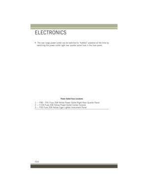
• The rear cargo power outlet can be switched to “battery” powered all the time byswitching the power outlet right rear quarter panel fuse in the fuse panel.
Power Outlet Fuse Locations
1 — F90 – F91 Fuse 20A Yellow Power Outlet Right Rear Quarter Panel
2 — F104 Fuse 20A Yellow Power Outlet Center Console
3 — F93 Fuse 20A Yellow Cigar Lighter Instrument Panel
ELECTRONICS
154
Page 157 of 276

QUADRA-TRAC I FOUR-WHEEL DRIVE
Quadra-Trac I Operating Instructions/Precautions — 3.6L Only
The Quadra-Trac I is a single-speed (HI range only) transfer case, which provides
convenient full-time four-wheel drive. No driver interaction is required. The Brake
Traction Control (BTC) System, which combines standard ABS and Traction Control,
provides resistance to any wheel that is slipping to allow additional torque transfer to
wheels with traction.
QUADRA-TRAC II/QUADRA-DRIVE II FOUR-WHEEL
DRIVE
Quadra-Trac II/Quadra-Drive II Operating Instructions/Precautions
The Quadra-Trac II/Quadra-Drive II transfer case is fully automatic in the normal
driving 4WD HI mode. The Quadra-Trac II/Quadra-Drive II transfer case provides
three mode positions:
• 4WD HI
• NEUTRAL
• 4WD LOW
This transfer case is fully automatic in
the 4WD HI mode.
When additional traction is required, the
4WD LOW position can be used to lock
the front and rear driveshafts together
and force the front and rear wheels to
rotate at the same speed. The 4WD LOW
position is intended for loose, slippery
surfaces only. Driving in the 4WD LOW
position on dry, hard-surfaced roads may
cause increased tire wear and damage to
driveline components.
When operating your vehicle in 4WD
LOW, the engine speed is approximately
three times that of the 4WD HI position at
a given road speed. Take care not to
overspeed the engine and do not exceed
25 mph (40 km/h).
The Neutral position disengages the pow-
ertrain from the wheels, allowing the ve-
hicle to be flat towed behind another vehicle.
Four Wheel Drive Controls
1 — 4WD Low Button
2 — Rotary Mode Control
3 — NEUTRAL Button
4 — Hill Descent Button
OFF-ROAD CAPABILITIES (4WD OPERATION)
155
Page 158 of 276

Shifting Procedures
4WD HI To 4WD LOW
With the vehicle at speeds of 0 to 3 mph (0 to 5 km/h), the ignition switch in the
ON/RUN position or the engine running, shift the transmission into NEUTRAL and
press the “4WD LOW” button once on the transfer case switch. The “4WD LOW”
indicator light in the instrument cluster will begin to flash and remain on solid when
the shift is complete.
4WD LOW To 4WD HI
With the vehicle at speeds of 0 to 3 mph (0 to 5 km/h), the ignition switch in the
ON/RUN position or the engine running, shift the transmission into NEUTRAL, and
press the “4WD LOW” button once on the transfer case switch. The “4WD LOW”
indicator light in the instrument cluster will flash and turn off when the shift is
complete.
NOTE:
Shifting into or out of 4WD LOW is possible with the vehicle completely stopped;
however, difficulty may occur due to the mating clutch teeth not being properly
aligned. Several attempts may be required for clutch teeth alignment and shift
completion to occur. The preferred method is with the vehicle rolling 0 to 3 mph
(0 to 5 km/h). If the vehicle is moving faster than 3 mph (5 km/h), the transfer case
will not allow the shift.
NEUTRAL Shift Procedure
WARNING!
You or others could be injured or killed if you leave the vehicle unattended with the
transfer case in the NEUTRAL (N) position without first fully engaging the parking
brake. The transfer case NEUTRAL (N) position disengages both the front and rear
driveshafts from the powertrain and will allow the vehicle to roll, even if the
transmission is in PARK. The parking brake should always be applied when the
driver is not in the vehicle.
1. Bring the vehicle to a complete stop, with the engine running.
2. Press and hold the brake pedal.
3. Shift the transmission into NEUTRAL.
4. If vehicle is equipped with Quadra-Lift air suspension, ensure the vehicle is set to Normal Ride Height.
OFF-ROAD CAPABILITIES (4WD OPERATION)
156
Page 159 of 276

5. Using a ballpoint pen or similar object, press and hold the recessed transfer caseNEUTRAL (N) button (located by the selector switch) for four seconds. The light
behind the N symbol will blink, indicating shift in progress. The light will stop
blinking (stay on solid) when the shift to NEUTRAL (N) is complete. A “FOUR
WHEEL DRIVE SYSTEM IN NEUTRAL” message will display on the Driver
Information Display (DID).
6. After the shift is completed and the NEUTRAL (N) light stays on, release the NEUTRAL (N) button.
7. Shift the transmission into REVERSE.
8. Release the brake pedal for five seconds and ensure that there is no vehicle movement.
9. Press and hold the brake pedal. Shift the transmission back into NEUTRAL
10. Firmly apply the parking brake.
11. With the transmission and transfer case in NEUTRAL, press and hold the ENGINE START/STOP button until the engine turns off.
12. Move the transmission gear selector to PARK. Release the brake pedal.
13. Push the ENGINE STOP/START button twice (without pressing the brake pedal), to turn the ignition switch to the OFF position
Repeat these Steps 1 through 5 to shift out of NEUTRAL.
SELEC-TERRAIN
Selec-Terrain combines the capabilities of the vehicle control systems, along with
driver input, to provide the best performance for all terrains.
Rotate the mode control knob to select the following Selec-Terrain positions:
Snow – Tuning set for additional stability in inclement weather. Use on and off road
on loose traction surfaces such as snow. When in Snow mode (depending on certain
operating conditions), the transmission may use second gear (rather than first gear)
during launches, to minimize wheel slippage. If equipped with air suspension, the
level will change to Normal Ride Height (NRH).
Auto – Fully automatic full time four-wheel drive operation can be used on and off
road. Balances traction with seamless steering feel to provide improved handling and
acceleration over two-wheel drive vehicles. If equipped with air suspension, the level
will change to NRH.
Sand – Off road calibration for use on low traction surfaces such as sand or wet grass.
Driveline is maximized for traction. Some binding may be felt on less forgiving
surfaces. The electronic brake controls are set to limit traction control management
of throttle and wheel spin. If equipped with air suspension, the level will change to
NRH.
OFF-ROAD CAPABILITIES (4WD OPERATION)
157
Page 160 of 276

Mud– Off road calibration for use on low traction surfaces such as mud. Driveline is
maximized for traction. Some binding may be felt on less forgiving surfaces. The
electronic brake controls are set to limit traction control management of throttle and
wheel spin. If equipped with air suspension, the level will change to Off-Road 1.
Rock – Off-road calibration only available in 4WD Low range. The vehicle is raised (if
equipped with Air Suspension) for improved ground clearance. Traction based tuning
with improved steer-ability for use on high traction off-road surfaces. Activate the Hill
Descent Control for steep downhill control. Use for low speed obstacles such as large
rocks, deep ruts, etc. If equipped with air suspension, the vehicle level will change
to Off-Road 2. If the Selec-Terrain switch is in ROCK mode, and the transfer case is
switched from 4WD Low to 4WD High, the Selec-Terrain system will return to AUTO.
QUADRA-LIFT
The Quadra-Lift air suspension system provides full time load leveling capability
along with the benefit of being able to adjust vehicle height by the push of a button.
Quadra-Lift is available with both Quadra-Trac II and Quadra-Drive II.
• The system requires that the engine be running for all changes. When lowering
the vehicle all of the doors, including
the liftgate, must be closed.
• The Quadra-Lift air suspension system uses a lifting and lowering pattern
which keeps the headlights from shin-
ing into oncoming traffic. When raising
the vehicle, the rear of the vehicle will
move up first and then the front. When
lowering the vehicle, the front will
move down first and then the rear.
• After the engine is turned off, you may notice that the air suspension system
operates briefly. This is normal. The
system is correcting the position of the
vehicle.
• To assist with changing a spare tire, the Quadra-Lift air suspension system
has a feature which allows the automatic leveling to be disabled. The feature
controls are located in the radio screen. Driving the vehicle over 5 mph (8 km/h)
will return the air suspension to normal operation.
• An audible chime will be heard whenever a system error has been detected.
Quadra-Lift Control
1 — UP Button
2 — DOWN Button
OFF-ROAD CAPABILITIES (4WD OPERATION)
158