Page 161 of 276

Operation
• Pushing the “Up” or “Down” button once will move the suspension one positionhigher or lower from the current position, assuming all conditions are met (i.e.,
engine running and all doors and liftgate closed).
• The 4 indicator lamps will illuminate to show the current position of the vehicle. Flashing indicator lamps will show a position which the system is working to
achieve. If multiple indicator lamps are flashing on the “Up” button, the highest
flashing indicator lamp is the position the system is working to achieve.
• Normal Ride Height (NRH) – This is the standard position of the suspension and is meant for normal driving. Only the bottom Indicator
lamp on the “Up” button will be illuminated when the vehicle is in this
position.
• Off-Road 1 (OR1) (Raises the vehicle approximately 1.1 in (28 mm) – This is the primary position for all off-road driving until OR2 is
needed. A smoother and more comfortable ride will result. Push the
“Up” button once from the NRH position while the vehicle speed is
below 38 mph (61 km/h). When in the OR1 position, if the vehicle
speed remains between 40 mph (64 km/h) and 50 mph (80 km/h) for greater than
20 seconds or if the vehicle speed exceeds 50 mph (80 km/h), the vehicle will be
automatically lowered to NRH.
• Off-Road 2 (OR2) (Raises the vehicle approximately 2.2 in (55 mm) – This position is intended for off-roading use only where maximum
ground clearance is required. To enter OR2, pushthe “Up” button
twice from the NRH position or once from the OR1 position while
vehicle speed is below 20 mph (32 km/h). While in OR2, if the vehicle
speed exceeds 25 mph (40 km/h), the vehicle height will be automatically lowered
to OR1.
• Entry/Exit Mode (Lowers the vehicle approximately 1.6 in (40 mm) – This position lowers the vehicle for easier passenger entry and exit as
well as lowering the rear of the vehicle for easier loading and
unloading of cargo. To enter Entry/Exit Mode, push the “Down” button
once from (NRH) while the vehicle speed is below 25 mph (40 km/h).
Once the vehicle speed goes below 15 mph (24 km/h), the vehicle height will
begin to lower. If the vehicle speed remains between 15 mph (24 km/h) and
25 mph (40 km/h) for greater than 60 seconds, or the vehicle speed exceeds
25 mph (40 km/h), the Entry/Exit Mode change will be cancelled. To exit Entry/Exit
Mode, push the “Up” button once while in Entry/Exit Mode or drive the vehicle
over 15 mph (24 km/h).
UP
UP
UP
DOWN
PARK
OFF-ROAD CAPABILITIES (4WD OPERATION)
159
Page 162 of 276

• Aero Mode (Lowers the vehicle approximately 0.6 in (15 mm) – This positionprovides improved aerodynamics by lowering the vehicle. The vehicle will auto-
matically enter Aero Mode when the vehicle speed remains between 52 mph
(83 km/h) and 56 mph (90 km/h) for greater than 20 seconds or if the vehicle
speed exceeds 56 mph (90 km/h). The vehicle will return to NRH from Aero Mode
if the vehicle speed remains between 20 mph (32 km/h) and 25 mph (40 km/h) for
greater than 20 seconds or if the vehicle speed falls below 20 mph (32 km/h). The
vehicle will enter Aero Mode, regardless of vehicle speed if the gear selector is in
the “SPORT” position.
• Transport Mode — To assist with flat bed towing, the air suspension system has a feature which will put the vehicle into Entry/Exit height and disable the automatic
load leveling system. Refer to “Programmable Features" (Uconnect Customer
Programmable Features) in “Electronics” for further information. Transport Mode
is selectable within the Suspension features.
NOTE:
This mode is intended to be enabled with engine running.
WARNING!
• You or others could be injured if you leave the vehicle unattended with the transfer case in the N (Neutral) position without first fully engaging the parking
brake. The transfer case N (Neutral) position disengages both the front and rear
driveshafts from the powertrain and will allow the vehicle to move regardless of
the transmission position. The parking brake should always be applied when
the driver is not in the vehicle.
• The air suspension system uses a high pressure volume of air to operate the
system. To avoid personal injury or damage to the system, see your authorized
dealer for service.
HILL START ASSIST/HILL DESCENT CONTROL/SELEC
SPEED CONTROL — IF EQUIPPED
• The Hill Start Assist system assists the driver when starting a vehicle from a stopon a hill.
• The Hill Descent Control system maintains vehicle speed while descending hills during off-road driving situations and is available in 4WD LOW range.
• The Selec Speed Control feature allows the driver to travel at slow speeds on level ground, uphill or downhill without actively controlling either the throttle or brake.
• Refer to your Owner's Manual on the DVD for further details.
OFF-ROAD CAPABILITIES (4WD OPERATION)
160
Page 163 of 276

TRAILER TOWING WEIGHTS (MAXIMUM TRAILER WEIGHT RATINGS)
Engine/Model Model CoolingFrontal Area Max. GTW (Gross Trailer Wt.) Max. Trailer Tongue Wt.
(See Note)
3.0L- Diesel En- gine 4x2 HD Cooling 55 sq ft (5.11 sq m) 7,400 lbs (3,357 kg) 740 lbs (336 kg)
3.0L- Diesel En- gine 4x4 HD Cooling 55 sq ft (5.11 sq m) 7,200 lbs (3,266 kg) 720 lbs (327 kg)
3.6L- Gasoline Engine 4x2 Std Cooling 55 sq ft (5.11 sq m) 3,500 lbs (1,588 kg) 350 lbs (159 kg)
3.6L- Gasoline Engine 4x2 HD Cooling 55 sq ft (5.11 sq m) 6,200 lbs (2,812kg) 620 lbs (281 kg)
3.6L- Gasoline Engine 4x4 Std Cooling 55 sq ft (5.11 sq m) 3,500 lbs (1,588 kgs) 350 lbs (159 kg)
3.6L- Gasoline Engine 4x4 HD Cooling 55 sq ft (5.11 sq m) 6,200 lbs (2,812kg) 620 lbs (281 kg)
5.7L- Gasoline Engine 4x2 Std Cooling 55 sq ft (5.11 sq m) 5,000 lbs (2,268 kg) 500 lbs (227 kg)
5.7L- Gasoline Engine 4x2 HD Cooling 55 sq ft (5.11 sq m) 7,400 lbs (3 357 kg) 740 lbs (336 kg)
5.7L- Gasoline Engine 4x4 Std Cooling 55 sq ft (5.11 sq m) 5,000 lbs (2,268 kg) 500 lbs (227 kg)
5.7L- Gasoline Engine 4x4 HD Cooling 55 sq ft (5.11 sq m) 7,200 lbs (3,266 kg) 720 lbs (327 kg)
UTILITY
161
Page 164 of 276
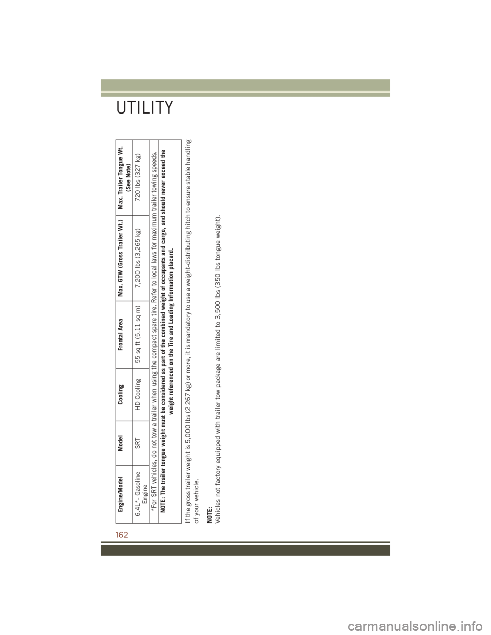
Engine/Model Model CoolingFrontal Area Max. GTW (Gross Trailer Wt.) Max. Trailer Tongue Wt.
(See Note)
6.4L*- Gasoline Engine SRT HD Cooling 55 sq ft (5.11 sq m) 7,200 lbs (3,265 kg) 720 lbs (327 kg)
*For SRT vehicles, do not tow a trailer when using the compact spare tire. Refer to local laws for maximum trailer towing speeds.
NOTE: The trailer tongue weight must be considered as part of the combined weight of occupants and cargo, and should never exceed the weight referenced on the Tire and Loading Information placard.
If the gross trailer weight is 5,000 lbs (2 267 kg) or more, it is mandatory to use a weight-distributing hitch to ensure stable handling
of your vehicle.
NOTE:
Vehicles not factory equipped with trailer tow package are limited to 3,500 lbs (350 lbs tongue weight).
UTILITY
162
Page 165 of 276
Trailer Hitch Receiver Cover Removal (Summit Models) — If Equipped
Your vehicle may be equipped with a trailer hitch receiver cover, this must be
removed to access the trailer hitch receiver (if equipped). This hitch receiver cover is
located at the bottom center of the rear fascia.
1. Turn the two locking retainers located at the bottom of the hitch receiver cover a1/4 turn counterclockwise.
NOTE:
Use a suitable tool such as a coin in the slot of the locking retainer if needed for
added leverage.
Hitch Receiver Cover
1 — Hitch Receiver Cover Tab
Locations
2 — Locking Retainers
UTILITY
163
Page 166 of 276
2. Pull the bottom of the cover outward (towards you), pull downwards to disengagethe tabs located at the top of the hitch receiver cover.
To reinstall the hitch receiver cover after
towing repeat the procedure in reverse
order.
NOTE:
Be sure to engage all tabs of the hitch receiver cover in the bumper fascia prior to
installation.
Hitch Receiver Cover
1 — Hitch Receiver Cover Tab Loca-
tions
2 — Locking Retainers
UTILITY
164
Page 167 of 276
Trailer Hitch Receiver Cover Removal (SRT Models) — If Equipped
Your vehicle may be equipped with a trailer hitch receiver cover, this must be
removed to access the trailer hitch receiver (if equipped). This hitch receiver cover is
located at the bottom center of the rear fascia.
1. Turn the two locking retainers located at the bottom of the hitch receiver cover a1/4 turn counterclockwise.
NOTE:
Use a suitable tool such as a coin in the slot of the locking retainer if needed for
added leverage.
Hitch Receiver Cover
1 — Hitch Receiver Cover Retaining
Tabs
2 — Hitch Receiver Cover
3 — Locking Retainers
UTILITY
165
Page 168 of 276
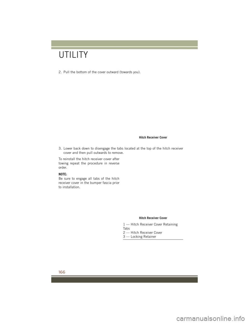
2. Pull the bottom of the cover outward (towards you).
3. Lower back down to disengage the tabs located at the top of the hitch receivercover and then pull outwards to remove.
To reinstall the hitch receiver cover after
towing repeat the procedure in reverse
order.
NOTE:
Be sure to engage all tabs of the hitch
receiver cover in the bumper fascia prior
to installation.
Hitch Receiver Cover
1 — Hitch Receiver Cover Retaining
Tabs
2 — Hitch Receiver Cover
3 — Locking Retainer
UTILITY
166