Page 177 of 276

SRT PERFORMANCE FEATURES
DID Performance Features
The DID can be used to program the following Performance Features.
• 0-60MPH
(0-100
km/h) • 0-100
MPH
(0-161
km/h) • 1/8 Mile
Timer • 1/4 Mile
Timer •60ft
Timer • Braking
Distance
• Current
G-Force •
Peak
G-Force • Lap
Timer • Lap
History •Top
Speed
0-60 MPH (0-100 km/h)
When selected, this screen displays the time it takes for the vehicle to go from 0 to
60 MPH (0 to 100 km/h).
0-100 MPH (0-161 km/h)
When selected, this screen displays the time it takes for the vehicle to go from 0 to
100 MPH (0 to 161 km/h).
Braking Distance
When selected, this screen displays the vehicle's braking distance and the speed at
which the brake pedal was depressed.
1/8 Mile, 1/4 Mile
When selected, this screen displays the time it takes the vehicle to travel 1/8 mile
(1/4 mile) within 30 seconds and the vehicle's speed when it reaches 1/8 mile (1/4
mile).
Instantaneous G-Force
When selected, this screen displays the current G-Force (lateral and longitudinal)
along with a friction circle that displays the directions of the forces.
Performance Features Controls
SRT
175
Page 178 of 276

Peak G-Force
When selected, this screen displays all four G-Force values (two lateral and two
longitudinal).
Uconnect SRT Performance Features
WARNING!
Measurement of vehicle statistics with the Performance Features is intended for
off-highway or off-road use only and should not be done on any public roadways.
It is recommended that these features be used in a controlled environment and
within the limits of the law. The capabilities of the vehicle as measured by the
performance pages must never be exploited in a reckless or dangerous manner,
which can jeopardize the user’s safety or the safety of others. Only a safe,
attentive, and skillful driver can prevent accidents.
• To access the SRT Performance Features, press the “Apps” button on the touchscreen then press the “Performance Pages” button on the touchscreen.
• The Performance Page includes the following menus:
• Home •
Gauges 2
• Timers •
G – Force
• Gauges 1 •
Engine
Home
When Home is selected, the following options will be available:
• A series of six images which can be selected by the user.
• A left and right arrow to allow the user to scroll through vehicle images.
• A short-cut to the Drive Modes feature.
Timers
When the Timers Page is selected you will be able to select from following “Tickets”:
Recent
• Pressing the “Recent” button displays a “real time” summary of performance
timers.
Last
• Pressing the “Last” button displays the last recorded run of performance timers.
Best
• Pressing the “Best” button displays the best recorded run of performance timers, except for braking data.
SRT
176
Page 179 of 276

Save
• Pressing the “Save” button will let you save the last run. Any saved run over 10,will overwrite the last saved run for Uconnect System storage. The operation of the
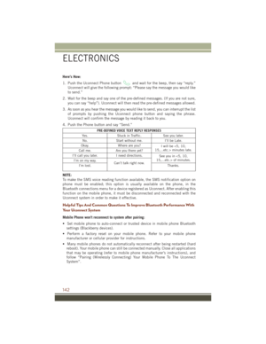
Save feature is listed below:• With a USB jump drive installed, press the “USB” button to save runs to the
jump drive.
• With an SD Card installed, press the “SD Card” to save runs to the SD Card.
• Press the “Uconnect” button to save the runs to the Owner web page.
• Press the “Cancel” button to view the last timer “Ticket.”
The “Tickets” contain the timers listed below:
0-60 MPH (0-100 km/h)
• Displays the time it takes for the vehicle to go from 0 to 60 mph (0 to 100 km/h).
0-100 MPH (0-160 km/h)
• Displays the time it takes for the vehicle to go from 0 to 100 mph (0 to 160 km/h).
⅛ Mile (200 meter)
• Displays the time it takes for the vehicle to go an ⅛Mile (200 meters).
¼ mile (400 meter)
• Displays the time it takes for the vehicle to go an ¼ mile (400 meters).
60 ft (18 Meters) time
• Displays the time it takes for the vehicle to go 60 ft (18 Meters).
Brake Distance
• Displays the distance it takes the vehicle to make a full stop. Contains current and last data for distance and start – from speed.
NOTE:
The distance measurement will be aborted if the brake pedal is released before the
vehicle comes to a complete stop.
Brake Speed
• Displays the speed the vehicle is traveling when the brake pedal is depressed.
NOTE:
Brake Distance and Speed timers will only display "ready" when vehicle is traveling
at greater than 30 MPH (48 km/h).
Gauges 1
When selected, this screen displays the following values:When selected, this screen
displays the following values:
Coolant Temperature
• Shows the actual coolant temperature.
Oil Temperature
• Shows the actual oil temperature.
Oil Pressure
• Shows the actual oil pressure.
SRT
177
Page 180 of 276

Gauges 2
When selected, this screen displays the following values:
Intake Air Temperature
• Shows the actual intake air temperature.
Battery Voltage
• Shows the actual battery voltage.
Transmission Temperature
• Shows the actual transmission temperature.
G-Force
When selected, this screen displays all four G-Force values (two lateral and two
longitudinal) as well as steering angle.
The following features are available:
Lateral G-Force Left and Right
• The lateral g-force measures the (sideways) left and right force of the vehicle.
Longitudinal G-Force Acceleration and Braking
• The longitudinal g-force measures the acceleration and braking force of thevehicle.
Peak G-Forces Acceleration and Braking, Left and Right
• This shows the maximum g-forces that have been achieved since the last reset from the DID. Peak values are maintained through ignition cycles by the DID until
they are cleared by the driver.
Vehicle Speed
• Vehicle Speed measures the current speed of the vehicle in either mph or km/h, starting at 0 with no maximum value.
Steering Wheel Angle
• Steering Wheel Angle utilizes the steering angle sensor to measure the degree of the steering wheel relative to zero. The zero degree measurement indicates a
steering wheel straight ahead position. When the steering angle value is negative,
this indicates a turn to the left, and when the steering angle value is positive, a turn
to the right.
SRT
178
Page 181 of 276

Engine
When selected, this screen displays the following values:
Vehicle Speed
• Shows the actual vehicle speed in mph or (km/h).
Instantaneous Horsepower/Kilowatts
• Shows instantaneous engine power.
Instantaneous Torque
• Shows instantaneous engine torque in Foot Pounds (lb/ft) or Newton Meters (Nm).
Oil Pressure
• Shows actual oil pressure in Pounds per Square Inch (PSI) or Kilopascals (kPa).
Gear
• Shows the current (or pending) operating transmission gear of the vehicle.
SUMMER/THREE-SEASON TIRES
• This vehicle may be equipped with wheels and tires to enhance traction in bothwet and dry conditions.
• Summer tires are not intended to be driven in snow or on ice.
• Summer tires have significantly reduced grip in temperatures below 50°F (10°C).
• Use Summer tires only in sets of four.
NOTE:
Summer tires will not contain the all season designation or mountain/snowflake
symbol on the sidewall of the tire.
WARNING!
Do not use summer tires in snow/ice conditions. You could lose control, resulting
in severe injury or death. Driving too fast for conditions also creates the possibility
of loss of vehicle control.
SRT
179
Page 182 of 276

DIESEL ENGINE BREAK-IN RECOMMENDATIONS
The diesel engine does not require a break-in period due to its construction. Normal
operation is allowed, providing the following recommendations are followed:
• Warm up the engine before placing it under load.
• Do not operate the engine at idle for prolonged periods.
• Use the appropriate transmission gear to prevent engine lugging.
• Observe vehicle oil pressure and temperature indicators.
• Check the coolant and oil levels frequently.
• Vary throttle position at highway speeds when carrying or towing significantweight.
NOTE:
Light duty operation such as light trailer towing or no load operation will extend the
time before the engine is at full efficiency. Reduced fuel economy and power may be
seen at this time.
The engine oil installed in the engine at the factory is a high-quality energy
conserving type lubricant. Oil changes should be consistent with anticipated climate
conditions under which vehicle operations will occur. NON-DETERGENT OR
STRAIGHT MINERAL OILS MUST NEVER BE USED.
DIESEL ENGINE STARTING PROCEDURES
Normal Starting Procedure
1. Apply the parking brake.
2. Ensure the gear selector is in the PARK position.
3. Press and hold the brake pedal while pushing the ENGINE START/STOP button once and the system will engage the starter to crank the engine.
NOTE: • A delay of the start of up to five seconds is possible under very cold conditions.The “Wait to Start” telltale will be illuminated during the pre-heat process,
When the engine Wait To Start light goes off the engine will automatically crank.
• If you wish to stop the cranking of the engine prior to the engine starting, push the button again.
4. Check that the oil pressure warning light has turned off.
5. Release the parking brake.
DIESEL
180
Page 183 of 276

CAUTION!
If the “Water in Fuel Indicator Light” remains on, DO NOT START the engine
before you drain the water from the fuel filters to avoid engine damage. Refer to
“Maintenance Procedures/Draining Fuel/Water Separator Filter” in “Maintaining
Your Vehicle” in your Diesel Supplement on the DVD for further information.
Extreme Cold Weather
The engine block heater is a resistance heater installed in the water jacket of the
engine. It requires a 110–115 Volt AC electrical outlet with a grounded, three-wire
extension cord.
Its use is recommended for environments that routinely fall below -10°F. It should be
used when the vehicle has not been running overnight or longer periods and should
be plugged in two hours prior to start. Its use is required for cold starts with
temperatures under -20°F.
A 12 Volt heater built into the fuel filter housing aids in preventing fuel gelling. It is
controlled by a built-in thermostat.
A Diesel Pre-Heat system both improves engine starting and reduces the amount of
white smoke generated by a warming engine.
NOTE:
The engine block heater cord is a factory installed option. If your vehicle is not
equipped, heater cords are available from your authorized MOPAR dealer.
Water In Fuel Message
If a Water In Fuel message orindicator appears in the cluster and a chime
sounds five times, the fuel/water separator will need to be drained immediately to
prevent engine damage.
Refer to “Draining Fuel Water Separator” in this guide for draining instructions or see
your dealer.
DIESEL
181
Page 184 of 276

DIESEL FUEL FILTERS/WATER SEPARATOR
Draining Fuel/Water Separator
If the “Water in Fuel” indicator light
is illuminated and an audible chime
is heard five times, you should stop the
engine and drain the water from the sepa-
rator.
The best access to this water drain valve
is from under the vehicle.
The drain valve is located on the bottom
of the Fuel Filter and Water Separator
assembly which is located on the left side
of the vehicle in front of the fuel tank.
1. Loosen the drain valve (located on the bottom of the filter assembly) then
turn the ignition switch to the ON/
RUN position to allow any accumu-
lated water to drain.
2. When clean fuel is visible, close the drain and switch the ignition to the OFF position.
Refer to the Diesel Supplement on the DVD for further details.
Fuel Filter Replacement
1. Ensure engine is turned off.
2. Place drain pan under the fuel filter assembly.
3. Open the water drain valve, and let any accumulated water drain.
4. Close the water drain valve.
5. Remove using a socket. Rotate counterclockwise for removal.
6. Remove the used filter cartridge from the housing and dispose of according to your local regulations.
7. Wipe clean the sealing surfaces of the lid and housing.
8. Lubricate o-ring on new filter with clean engine oil.
9. Repeat steps 5 through 8 to service second filter in fuel filter assembly.
Fuel Filter And Water Separator Assembly
1 — Fuel Filter Access
2 — Water In Fuel Drain
DIESEL
182