2014 NISSAN TEANA lock
[x] Cancel search: lockPage 3956 of 4801
VEHICLE SECURITY SYSTEM CANNOT BE SETSEC-131
< SYMPTOM DIAGNOSIS >
C
D E
F
G H
I
J
L
M A
B
SEC
N
O P
VEHICLE SECURITY S YSTEM CANNOT BE SET
INTELLIGENT KEY
INTELLIGENT KEY : DescriptionINFOID:0000000009461198
ARMED phase is not activated when door is locked using Intelligent Key.
NOTE:
Check that vehicle is under the condition shown in “C onditions of vehicle” before starting diagnosis and check
each symptom.
CONDITION OF VEHICLE (OPERATING CONDITION)
Confirm the setting of “SECURITY ALARM SET” is ON in “WORK SUPPORT” mode of “THEFT ALM” of
“BCM” using CONSULT.
INTELLIGENT KEY : Diagnosis ProcedureINFOID:0000000009461199
1.CHECK INTELLIGENT KEY SYSTEM (REMOTE KEYLESS ENTRY FUNCTION)
Lock/unlock door with Intelligent Key.
Refer to SEC-11, "INTELLIGENT KEY SYSTEM/ENGIN E START FUNCTION : System Description"
.
Is the inspection result normal?
YES >> GO TO 2.
NO >> Check Intelligent Key system (remote keyless entry function). Refer to DLK-144, "Diagnosis Pro-
cedure".
2.CHECK HOOD SWITCH
Check hood swiwtch.
Refer to SEC-125, "Component Function Check"
.
Is the inspection result normal?
YES >> GO TO 3.
NO >> Repair or replace hood switch.
3.CONFIRM THE OPERATION
Confirm the operation again.
Is the result normal?
YES >> Check intermittent incident. Refer to GI-43, "Intermittent Incident".
NO >> GO TO 1.
DOOR REQUEST SWITCH
DOOR REQUEST SWITCH : DescriptionINFOID:0000000009461200
ARMED phase is not activated when door is locked using door request switch.
NOTE:
Check that vehicle is under the condition shown in “C onditions of vehicle” before starting diagnosis, and check
each symptom.
CONDITION OF VEHICLE (OPERATING CONDITION)
Confirm the setting of “SECURITY ALARM SET” is ON in “WORK SUPPORT” mode of “THEFT ALM” of
“BCM” using CONSULT.
DOOR REQUEST SWITCH : Diagnosis ProcedureINFOID:0000000009461201
1.CHECK INTELLIGENT KEY SYS TEM (DOOR LOCK FUNCTION)
Lock/unlock door with door request switch.
Refer to SEC-16, "VEHICLE SECURITY SY STEM : System Description"
.
Is the inspection result normal?
YES >> GO TO 2.
NO >> Check Intelligent Key system (door lock function). Refer to DLK-144, "Diagnosis Procedure"
.
Revision: November 20132014 Altima NAMRevision: November 20132014 Altima NAM
Page 3957 of 4801

SEC-132
< SYMPTOM DIAGNOSIS >
VEHICLE SECURITY SYSTEM CANNOT BE SET
2.CHECK HOOD SWITCH
Check hood switch.
Refer to SEC-125, "Component Function Check"
.
Is the inspection result normal?
YES >> GO TO 3.
NO >> Repair or replace hood switch.
3.CONFIRM THE OPERATION
Confirm the operation again.
Is the result normal?
YES >> Check intermittent incident. Refer to GI-43, "Intermittent Incident".
NO >> GO TO 1.
DOOR KEY CYLINDER
DOOR KEY CYLINDER : DescriptionINFOID:0000000009461202
ARMED phase is not activated when door is locked using mechanical key.
NOTE:
Check that vehicle is under the condition shown in “C onditions of vehicle” before starting diagnosis, and check
each symptom.
CONDITION OF VEHICLE (OPERATING CONDITION)
Confirm the setting of “SECURITY ALARM SET” is ON in “WORK SUPPORT” mode of “THEFT ALM” of
“BCM” using CONSULT.
DOOR KEY CYLINDER : Diagnosis ProcedureINFOID:0000000009461203
1.CHECK POWER DOOR LOCK SYSTEM
Lock/unlock door with mechanical key.
Refer to SEC-16, "VEHICLE SECURITY SYSTEM : System Description"
.
Is the inspection result normal?
YES >> GO TO 2.
NO >> Check power door lock system. Refer to DLK-144, "Diagnosis Procedure"
.
2.CONFIRM THE OPERATION
Confirm the operation again.
Is the result normal?
YES >> Check intermittent incident. Refer to GI-43, "Intermittent Incident".
NO >> GO TO 1.
Revision: November 20132014 Altima NAMRevision: November 20132014 Altima NAM
Page 3959 of 4801
SEC-134
< SYMPTOM DIAGNOSIS >
PANIC ALARM FUNCTION DOES NOT OPERATE
PANIC ALARM FUNCTION DOES NOT OPERATE
DescriptionINFOID:0000000009461206
NOTE:
• Before performing the diagnosis following procedure, check “Work Flow”. Refer to SEC-63, "Work Flow"
.
• Check that vehicle is under the condition shown in “Conditions of vehicle” before starting diagnosis and
check each symptom.
CONDITIONS OF VEHICLE (OPERATION CONDITIONS)
• Ignition switch is in OFF or LOCK position.
• Intelligent Key is removed from key slot.
Diagnosis ProcedureINFOID:0000000009461207
1.CHECK REMOTE KEYL ESS ENTRY FUNCTION
Check remote keyless entry function.
Does door lock/unlock with Intelligent Key button?
YES >> GO TO 2.
NO >> Go to DLK-146, "Component Function Check"
.
2.CHECK VEHICLE SECURITY ALARM OPERATION
Check vehicle security alarm operation.
Does alarm (headlamps and horns) active?
YES >> GO TO 3.
NO >> Go to SEC-16, "VEHICLE SECURITY SYSTEM : System Description"
.
3.CHECK “PANIC ALARM SET” SETTING IN “WORK SUPPORT”
Check “PANIC ALARM SET” setting in “WORK SUPPORT”.
Refer to BCS-22, "INTELLIGENT KEY : CONSULT Function (BCM - INTELLIGENT KEY)"
.
Is the inspection result normal?
YES >> GO TO 4.
NO >> Set “PANIC ALARM SET” setting in “WORK SUPPORT”.
4.CONFIRM THE OPERATION
Confirm the operation again.
Is the result normal?
YES >> Check intermittent incident. Refer to GI-43, "Intermittent Incident".
NO >> GO TO 1.
Revision: November 20132014 Altima NAMRevision: November 20132014 Altima NAM
Page 3975 of 4801
DRIVER AIR BAG MODULESR-13
< REMOVAL AND INSTALLATION >
C
D E
F
G
I
J
K L
M A
B
SR
N
O P
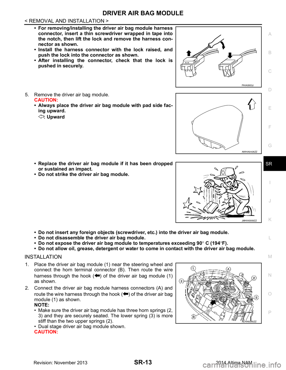
• For removing/installing the driver air bag module harness
connector, insert a thin screwdriver wrapped in tape into
the notch, then lift the lock and remove the harness con-
nector as shown.
• Install the harness connector with the lock raised, and push the lock into the connector as shown.
• After installing the connector, check that the lock is pushed in securely.
5. Remove the driver air bag module. CAUTION:
• Always place the driver air ba g module with pad side fac-
ing upward.
: Upward
• Replace the driver air bag module if it has been dropped or sustained an impact.
• Do not strike the driver air bag module.
• Do not insert any foreign objects (screwdri ver, etc.) into the driver air bag module.
• Do not disassemble the driver air bag module.
• Do not expose the driver air ba g module to temperatures exceeding 90 ° C (194 °F).
• Do not allow oil, grease, detergent or water to come in contact with the driver air bag module.
INSTALLATION
1. Place the driver air bag module (1) near the steering wheel and
connect the horn terminal connec tor (B). Then route the wire
harness through the hook ( ) of the driver air bag module (1)
as shown.
2. Connect the driver air bag module harness connectors (A) and route the wire harness through the hook ( ) of the driver air bag
module (1) as shown.
NOTE:
• Make sure the driver air bag module has three horn springs (2, 3) and they are securely seated. The lower spring (3) is more
stiff than the two upper springs (2).
• Dual stage driver air bag module shown.
CAUTION:
PHIA0953J
AWHIA0426ZZ
JMHIA0009ZZ
ALHIA0265ZZ
Revision: November 20132014 Altima NAM
Page 3976 of 4801
SR-14
< REMOVAL AND INSTALLATION >
DRIVER AIR BAG MODULE
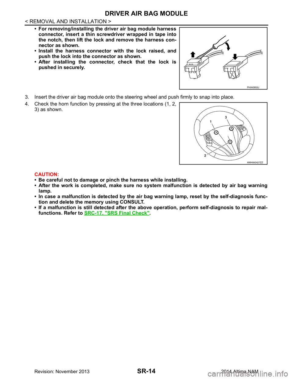
• For removing/installing the driver air bag module harnessconnector, insert a thin screwdriver wrapped in tape into
the notch, then lift the lock and remove the harness con-
nector as shown.
• Install the harness connector with the lock raised, and push the lock into the connector as shown.
• After installing the conn ector, check that the lock is
pushed in securely.
3. Insert the driver air bag module onto the st eering wheel and push firmly to snap into place.
4. Check the horn function by pressing at the three locations (1, 2, 3) as shown.
CAUTION:
• Be careful not to damage or pinch the harness while installing.
• After the work is completed, make sure no syst em malfunction is detected by air bag warning
lamp.
• In case a malfunction is detected by the air bag warning lamp, reset by the self-diagnosis func-
tion and delete the memory using CONSULT.
• If a malfunction is still detected after the abo ve operation, perform self-diagnosis to repair mal-
functions. Refer to SRC-17, "SRS Final Check"
.
PHIA0953J
AWHIA0427ZZ
Revision: November 20132014 Altima NAM
Page 3978 of 4801
SR-16
< REMOVAL AND INSTALLATION >
SPIRAL CABLE
• Do not strike or drop the spiral cable.
• Replace the spiral cable if it has been dropped or sus-
tained an impact.
• Do not disassemble the spiral cable.
• Do not allow oil, grease, detergent or water to come in contact with the spiral cable.
INSTALLATION
Installation is in the reverse order of removal.
• The turn signal lever must be in the neutral position for spiral cable installation.
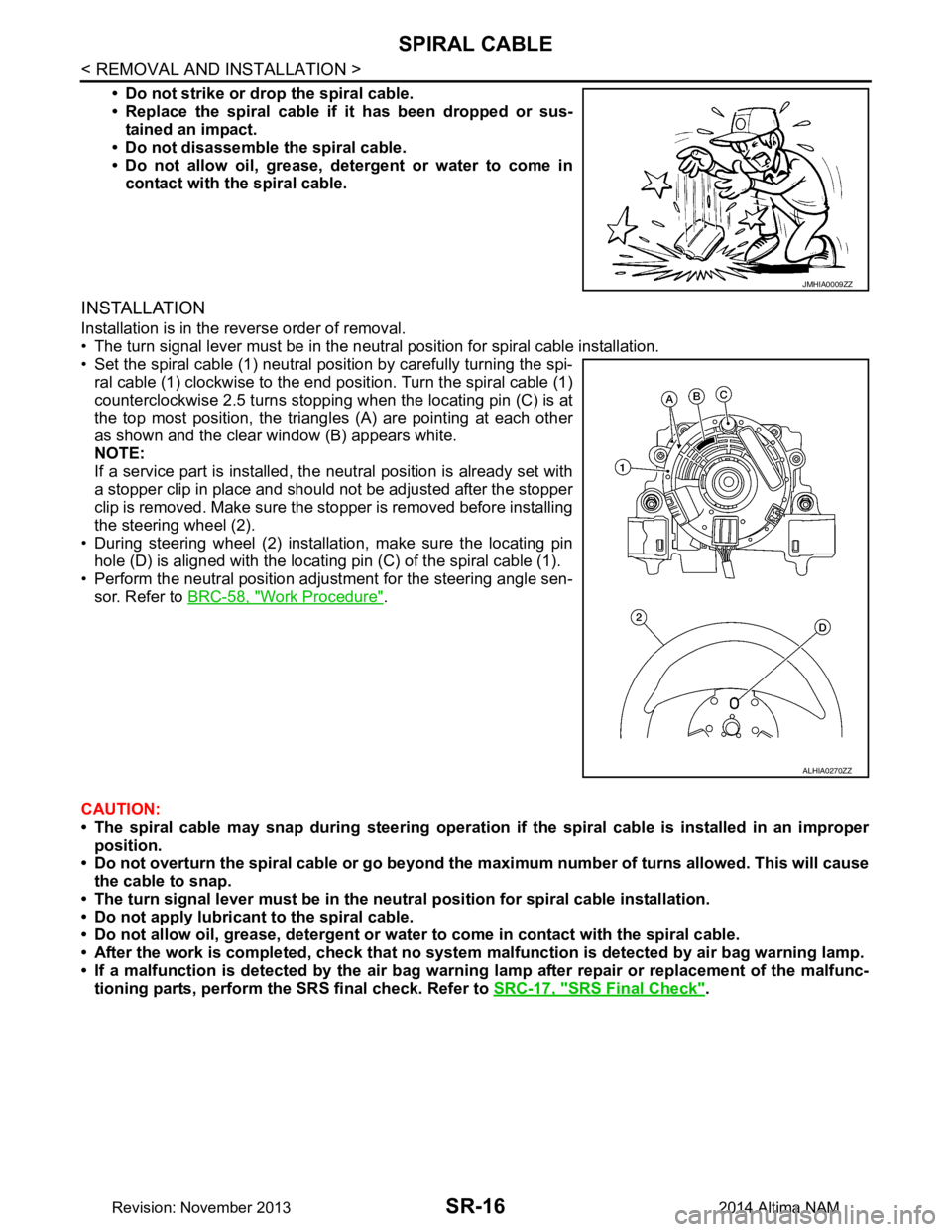
• Set the spiral cable (1) neutral position by carefully turning the spi-
ral cable (1) clockwise to the end position. Turn the spiral cable (1)
counterclockwise 2.5 turns stopping when the locating pin (C) is at
the top most position, the triangl es (A) are pointing at each other
as shown and the clear window (B) appears white.
NOTE:
If a service part is installed, the neutral position is already set with
a stopper clip in place and should not be adjusted after the stopper
clip is removed. Make sure the stopper is removed before installing
the steering wheel (2).
• During steering wheel (2) installation, make sure the locating pin hole (D) is aligned with the locating pin (C) of the spiral cable (1).
• Perform the neutral position adjustment for the steering angle sen-
sor. Refer to BRC-58, "Work Procedure"
.
CAUTION:
• The spiral cable may snap during steering operation if the spiral cable is installed in an improper
position.
• Do not overturn the spiral cable or go beyond the maximum number of turns allowed. This will cause
the cable to snap.
• The turn signal lever must be in the ne utral position for spiral cable installation.
• Do not apply lubricant to the spiral cable.
• Do not allow oil, grease, detergent or water to come in contact with the spiral cable.
• After the work is completed, check that no system malfunction is detected by air bag warning lamp.
• If a malfunction is detected by the air bag warnin g lamp after repair or replacement of the malfunc-
tioning parts, perform the SRS final check. Refer to SRC-17, "SRS Final Check"
.
JMHIA0009ZZ
ALHIA0270ZZ
Revision: November 20132014 Altima NAM
Page 3982 of 4801
SR-20
< REMOVAL AND INSTALLATION >
SIDE CURTAIN AIR BAG MODULE
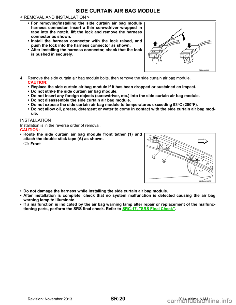
• For removing/installing the side curtain air bag moduleharness connector, insert a thin screwdriver wrapped in
tape into the notch, lift the lock and remove the harness
connector as shown.
• Install the harness connector with the lock raised, and push the lock into the harness connector as shown.
• After installing the harness connector, check that the lock
is pushed in securely.
4. Remove the side curtain air bag module bolts, then remove the side curtain air bag module. CAUTION:
• Replace the side curtain air bag module if it has been dropped or sustained an impact.
• Do not strike the side curtain air bag module.
• Do not insert any foreign objects (screwdriver , etc.) into the side curtain air bag module.
• Do not disassemble the side curtain air bag module.
• Do not expose the side curtain air bag module to temperatures exceeding 93 °C (200 °F).
• Do not allow oil, grease, detergent or water to co me in contact with the side curtain air bag mod-
ule.
INSTALLATION
Installation is in the reverse order of removal.
CAUTION:
• Route the side curtain air bag module front tether (1) and attach the double stick tape (A) as shown.
: Front
• Do not damage the harness while installi ng the side curtain air bag module.
• After installation is complete, check that no syst em malfunction is detected causing the air bag
warning lamp to illuminate.
• If a malfunction is indicated by the air bag warnin g lamp after repair or replacement of the malfunc-
tioning parts, perform the SRS final check. Refer to SRC-17, "SRS Final Check"
.
PHIA0953J
ALHIA0263ZZ
Revision: November 20132014 Altima NAM
Page 4002 of 4801
COMPONENT PARTSSRC-9
< SYSTEM DESCRIPTION >
C
D E
F
G
I
J
K L
M A
B
SRC
N
O P
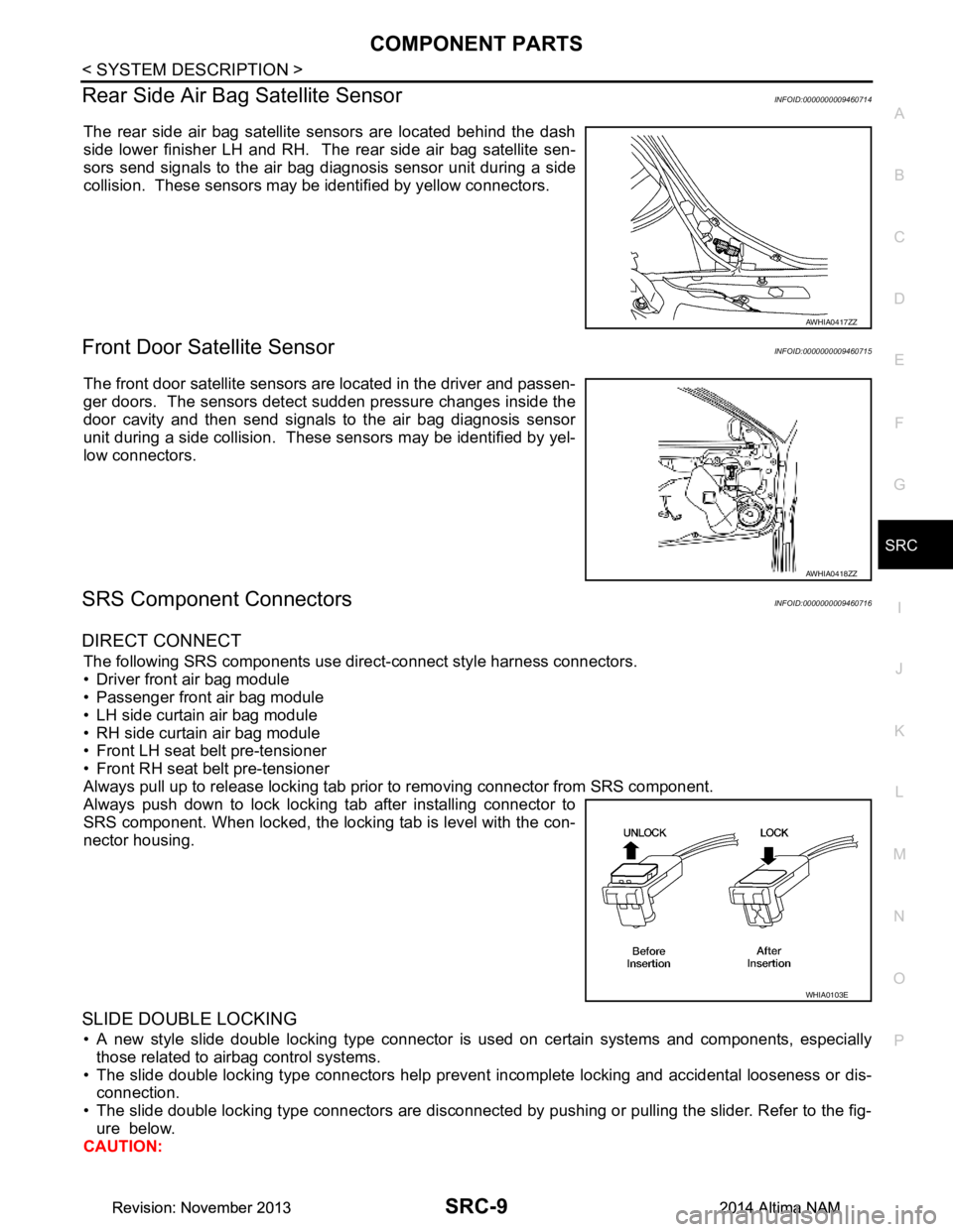
Rear Side Air Bag Satellite SensorINFOID:0000000009460714
The rear side air bag satellite sensors are located behind the dash
side lower finisher LH and RH. The rear side air bag satellite sen-
sors send signals to the air bag diagnosis sensor unit during a side
collision. These sensors may be identified by yellow connectors.
Front Door Satellite SensorINFOID:0000000009460715
The front door satellite sensors are located in the driver and passen-
ger doors. The sensors detect sudden pressure changes inside the
door cavity and then send signals to the air bag diagnosis sensor
unit during a side collision. These sensors may be identified by yel-
low connectors.
SRS Component ConnectorsINFOID:0000000009460716
DIRECT CONNECT
The following SRS components use dire ct-connect style harness connectors.
• Driver front air bag module
• Passenger front air bag module
• LH side curtain air bag module
• RH side curtain air bag module
• Front LH seat belt pre-tensioner
• Front RH seat belt pre-tensioner
Always pull up to release locking tab prior to removing connector from SRS component.
Always push down to lock locking tab after installing connector to
SRS component. When locked, the locking tab is level with the con-
nector housing.
SLIDE DOUBLE LOCKING
• A new style slide double locking type connector is used on certain systems and components, especially those related to airbag control systems.
• The slide double locking type connectors help prevent incomplete locking and accidental looseness or dis- connection.
• The slide double locking type connectors are disconnected by pushing or pulling the slider. Refer to the fig-
ure below.
CAUTION:
AWHIA0417ZZ
AWHIA0418ZZ
WHIA0103E
Revision: November 20132014 Altima NAMRevision: November 20132014 Altima NAM