2014 NISSAN TEANA lock
[x] Cancel search: lockPage 3848 of 4801

DIAGNOSIS SYSTEM (BCM)SEC-23
< SYSTEM DESCRIPTION >
C
D E
F
G H
I
J
L
M A
B
SEC
N
O P
WORK SUPPORT
PUSH SWITCH INDICATOR This test is able to check push-button ignition switch indicator operation [On/Off].
ACC CONT This test is able to check ac cessory relay control operation [On/Off].
IGN CONT1 This test is able to check ignition relay-1 control operation [On/Off].
ST CONT LOW This test is able to check starter control relay operation [On/Off].
IGNITION RELAY This test is able to ignition relay operation [On/Off].
REVERSE LAMP TEST This test is able to check reverse lamp illuminatio n operation [On/Off].
TRUNK/LUGGAGE LAMP TEST This test is able to check cargo lamp illumination operation [On/Off].
KEYFOB PW TEST This test is able to check power window operation using the Inte lligent Key [Off/DOWN/UP].
SHIFTLOCK SOLENOID TEST This te st is able to check shift lock solenoid operation [On/Off].
Test Item Description
Support Item Setting Description
IGN/ACC BATTERY SAVER On* Battery saver function ON.
Off Battery saver function OFF.
REMOTE ENGINE STARTER On* Remote engine start function ON.
Off Remote engine start function OFF.
ANSWERBACK I-KEY LOCK UNLOCK BUZZER Buzzer reminder function by door lock/unlock request switch ON.
HORN Horn chirp reminder function by door lock request switch ON.
Off* No reminder function by door lock/unlock request switch.
INVALID This mode is not used.
ANSWERBACK KEYLESS LOCK UN-
LOCK On
Buzzer or horn chirp reminder when doors are locked/unlocked with
Intelligent Key.
Off* No buzzer or horn chirp reminder when doors are locked/unlocked
with Intelligent Key.
ANSWER BACK On* Horn chirp reminder when doors are locked with Intelligent Key.
Off No horn chirp reminder when doors are locked with Intelligent Key.
RETRACTABLE MIRROR SET On Retractable mirror set ON.
Off* Retractable mirror set OFF.
CONFIRM KEY FOB ID — Intellige nt Key ID code can check.
LOCK/UNLOCK BY I-KEY On* Door lock/unlock function from Intelligent Key ON.
Off Door lock/unlock function from Intelligent Key OFF.
ENGINE START BY I-KEY On* Engine start function from Intelligent Key ON.
Off Engine start function from Intelligent Key OFF.
TRUNK/GLASS HATCH OPEN On* Buzzer reminder function by trunk opener request switch ON.
Off Buzzer reminder function by trunk opener request switch OFF.
INTELLIGENT KEY LINK SET On Intelligent Key link set ON.
Off* Intelligent Key link set OFF.
SHORT CRANKING OUTPUT Start70 msec
Starter motor operation duration times.
100 msec
200 msec
End —
INSIDE ANT DIAGNOSIS — This function allo ws inside key antenna self-diagnosis.
Revision: November 20132014 Altima NAMRevision: November 20132014 Altima NAM
Page 3849 of 4801

SEC-24
< SYSTEM DESCRIPTION >
DIAGNOSIS SYSTEM (BCM)
*: Initial Setting
THEFT ALM
THEFT ALM : CONSULT Function (BCM - THEFT ALM)INFOID:0000000009955727
CAUTION:
After disconnecting the CONSULT vehicle interface (VI) from the data link connector, the ignition must
be cycled OFF → ON (for at least 5 seconds) → OFF. If this step is not performed, the BCM may not go
to ”sleep mode”, potentially causing a di scharged battery and a no-start condition.
DATA MONITOR
ACTIVE TEST
WORK SUPPORT
AUTO LOCK SET MODE7 5 min
Auto door lock time can be set in this mode.
MODE6 4 min
MODE5 3 min
MODE4 2 min
MODE3* 1 min
MODE2 30 sec
MODE1 Off
Support Item Setting Description
Monitored Item Description
REQ SW -DR [On/Off] Indicates condition of door request switch LH.
REQ SW -AS [On/Off] Indicates condition of door request switch RH.
REQ SW -BD/TR [ON/OFF] Indicates condition of trunk opener request switch.
PUSH SW [On/Off] Indicates condition of push-button ignition switch.
UNLK SEN -DR [On/Off] Indicates condition of door unlock sensor.
DOOR SW-DR [On/Off] Indicates condition of front door switch LH.
DOOR SW-AS [On/Off] Indicates condition of front door switch RH.
DOOR SW-RR [On/Off] Indicates condition of rear door switch RH.
DOOR SW-RL [On/Off] Indicates condition of rear door switch LH.
DOOR SW-BK [On/Off] Indicates condition of trunk switch.
CDL LOCK SW [On/Off] Indicates condition of lock signal from door lock and unlock switch.
CDL UNLOCK SW [On/Off] Indicates condition of unlock signal from door lock and unlock switch.
KEY CYL LK-SW [On/Off] Indicates condition of lock signal from door key cylinder switch.
KEY CYL UN-SW [On/Off] Indicates condition of unlock signal from door key cylinder switch.
TR/BD OPEN SW [On/Off] Indicates condition of trunk opener switch.
TRNK/HAT MNTR [On/Off] Indicates condition of trunk room lamp switch.
RKE-LOCK [On/Off] Indicates condition of lock signal from Intelligent Key.
RKE-UNLOCK [On/Off] Indicates condition of unlock signal from Intelligent Key.
RKE-TR/BD [On/Off] Indicates condition of trunk open signal from Intelligent Key.
Test Item Description
FLASHER This test is able to check turn signal lamp operation [LH/RH/Off].
THEFT IND This test is able to check se curity indicator lamp operation [On/Off].
VEHICLE SECURITY HORN This test is able to check vehicle security horn operation [On].
HEADLAMP(HI) This test is able to check vehicle security lamp operation [On].
Revision: November 20132014 Altima NAMRevision: November 20132014 Altima NAM
Page 3851 of 4801

SEC-26
< SYSTEM DESCRIPTION >
DIAGNOSIS SYSTEM (IPDM E/R)
DIAGNOSIS SYSTEM (IPDM E/R)
CONSULT Function (IPDM E/R)INFOID:0000000009955729
CAUTION:
After disconnecting the CONSULT vehicle interface (VI) from the data link connector, the ignition must
be cycled OFF → ON (for at least 5 seconds) → OFF. If this step is not performed, the BCM may not go
to ”sleep mode”, potentially causing a di scharged battery and a no-start condition.
APPLICATION ITEM
CONSULT performs the following functions via CAN communication with IPDM E/R.
ECU IDENTIFICATION
The IPDM E/R part number is displayed.
SELF DIAGNOSTIC RESULT
Refer to PCS-20, "DTC Index".
DATA MONITOR
Direct Diagnostic Mode Description
Ecu Identification The IPDM E/R part number is displayed.
Self Diagnostic Result The IPDM E/R self diagnostic results are displayed.
Data Monitor The IPDM E/R input/output data is displayed in real time.
Active Test The IPDM E/R activates outputs to test components.
CAN Diag Support Mntr The result of transmit/receive diagnosis of CAN communication is displayed.
Monitor Item [Unit] Main
Signals Description
MOTOR FAN REQ [%] ×Indicates cooling fan speed signal received from ECM on CAN communication
line
AC COMP REQ [On/Off] ×Indicates A/C compressor request signal received from ECM on CAN commu-
nication line
TAIL&CLR REQ [On/Off] ×Indicates position light request signal received from BCM on CAN communica-
tion line
HL LO REQ [On/Off] ×Indicates low beam request signal received from BCM on CAN communication
line
HL HI REQ [On/Off] ×Indicates high beam request signal received from BCM on CAN communication
line
FR FOG REQ [On/Off] ×Indicates front fog light request signal received from BCM on CAN communica-
tion line
FR WIP REQ [Stop/1LOW/Low/Hi] ×Indicates front wiper request signal received from BCM on CAN communication
line
WIP AUTO STOP [STOP P/ACT P] ×Indicates condition of front wiper auto stop signal
WIP PROT [Off/BLOCK] ×Indicates condition of front wiper fail-safe operation
IGN RLY1 -REQ [On/Off] Indicates ignition switch ON signal received from BCM on CAN communication
line
IGN RLY [On/Off] ×Indicates condition of ignition relay
PUSH SW [On/Off] Indicates condition of push-button ignition switch
INTER/NP SW [On/Off] Indicates condition of CVT shift position
ST RLY CONT [On/Off] Indicates starter relay status signal received from BCM on CAN communication
line
IHBT RLY -REQ [On/Off] Indicates starter control relay signal received from BCM on CAN communication
line
Revision: November 20132014 Altima NAMRevision: November 20132014 Altima NAM
Page 3893 of 4801

SEC-68
< DTC/CIRCUIT DIAGNOSIS >
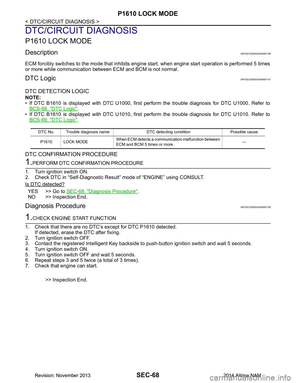
P1610 LOCK MODE
DTC/CIRCUIT DIAGNOSIS
P1610 LOCK MODE
DescriptionINFOID:0000000009461106
ECM forcibly switches to the mode that inhibits engine start, when engine start operation is performed 5 times
or more while communication between ECM and BCM is not normal.
DTC LogicINFOID:0000000009461107
DTC DETECTION LOGIC
NOTE:
• If DTC B1610 is displayed with DTC U1000, first perform the trouble diagnosis for DTC U1000. Refer to BCS-68, "DTC Logic"
.
• If DTC B1610 is displayed with DTC U1010, first perform the trouble diagnosis for DTC U1010. Refer to BCS-69, "DTC Logic"
.
DTC CONFIRMATION PROCEDURE
1.PERFORM DTC CONFIRMATION PROCEDURE
1. Turn ignition switch ON.
2. Check DTC in “Self-Diagnostic Result” mode of “ENGINE” using CONSULT.
Is DTC detected?
YES >> Go to SEC-68, "Diagnosis Procedure".
NO >> Inspection End.
Diagnosis ProcedureINFOID:0000000009461108
1.CHECK ENGINE START FUNCTION
1. Check that there are no DTC’s except for DTC P1610 detected. If detected, erase the DTC after fixing.
2. Turn ignition switch OFF.
3. Contact the registered Intelligent Key backside to push-button ignition switch and wait 5 seconds.
4. Turn ignition switch ON.
5. Turn ignition switch OFF and wait 5 seconds.
6. Repeat steps 3 and 5 twice (a total of 3 times).
7. Check that engine can start.
>> Inspection End.
DTC No. Trouble diagnosis name DTC detecting condition Possible causeP1610 LOCK MODE When ECM detects a communication malfunction between
ECM and BCM 5 times or more. —
Revision: November 20132014 Altima NAMRevision: November 20132014 Altima NAM
Page 3919 of 4801

SEC-94
< DTC/CIRCUIT DIAGNOSIS >
B2555 STOP LAMP
B2555 STOP LAMP
DTC LogicINFOID:0000000009461150
DTC DETECTION LOGIC
DTC CONFIRMATION PROCEDURE
1.PERFORM DTC CONFIRMATION PROCEDURE
1. Depress the brake pedal and wait 1 second or more.
2. Check DTC in “Self-Diagnostic Result” mode of “BCM” using CONSULT.
Is DTC detected?
YES >> Go to SEC-94, "Diagnosis Procedure".
NO >> Inspection End.
Diagnosis ProcedureINFOID:0000000009461151
Regarding Wiring Diagram information, refer to SEC-29, "Wiring Diagram".
1. CHECK STOP LAMP SWITCH INPUT SIGNAL
1. Turn ignition switch OFF.
2. Disconnect BCM connector M17.
3. Check voltage between BCM harness connector and ground.
Is the inspection result normal?
YES >> GO TO 8.
NO >> GO TO 2.
2. CHECK POWER SOURCE (STOP LAMP SWITCH)
1. Disconnect stop lamp switch connector.
2. Check voltage between stop lamp switch connector E38 terminal 1 and ground.
Is the inspection result normal?
YES >> GO TO 3.
NO >> Check the following: • Harness for short or open between fuse block (J/B) and stop lamp switch
• 10A fuse (No. 10, located in fuse block [J/B])
3.CHECK STOP LAMP SWITCH
DTC No. Trouble diagnosis name DTC detecting condition Possible cause
B2555 STOP LAMP BCM makes a comparison between the
upper voltage and lower voltage of stop
lamp switch. It judges from their values to
detect the malfunctioning circuit. • Harness or connectors
(Stop lamp switch circuit is open or
shorted.)
• Stop lamp switch
•Fuse
•BCM
(+) (-) Condition Voltage (V)
BCM
Connector Terminal Ground Brake pedal Depressed Battery voltage
M17 27 Not depressed 0
Stop lamp switch GroundVoltage
Connector Terminal
E38 1 Battery voltage
Revision: November 20132014 Altima NAMRevision: November 20132014 Altima NAM
Page 3951 of 4801

SEC-126
< DTC/CIRCUIT DIAGNOSIS >
HOOD SWITCH
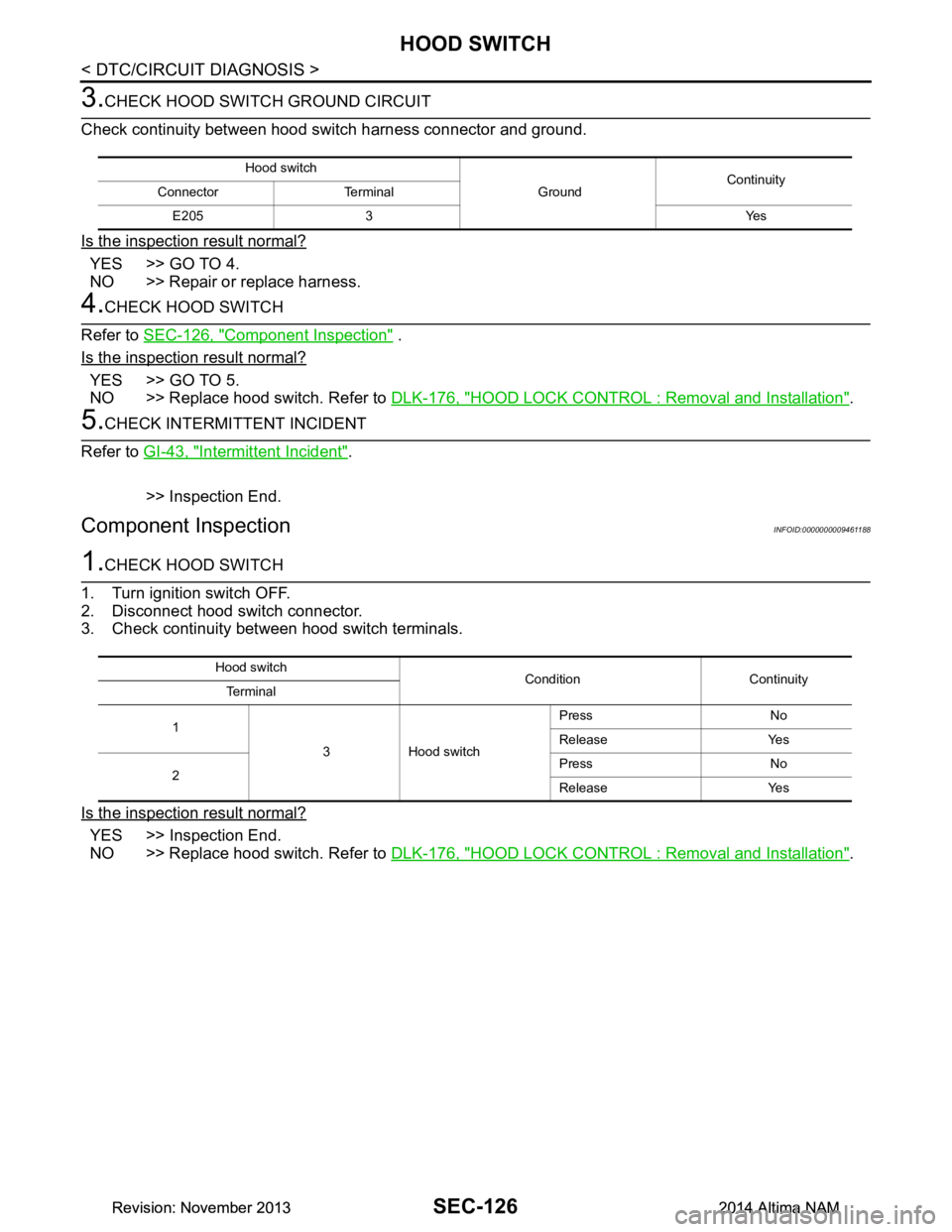
3.CHECK HOOD SWITCH GROUND CIRCUIT
Check continuity between hood switch harness connector and ground.
Is the inspection result normal?
YES >> GO TO 4.
NO >> Repair or replace harness.
4.CHECK HOOD SWITCH
Refer to SEC-126, "Component Inspection"
.
Is the inspection result normal?
YES >> GO TO 5.
NO >> Replace hood switch. Refer to DLK-176, "HOOD LOCK CONTROL : Removal and Installation"
.
5.CHECK INTERMITTENT INCIDENT
Refer to GI-43, "Intermittent Incident"
.
>> Inspection End.
Component InspectionINFOID:0000000009461188
1.CHECK HOOD SWITCH
1. Turn ignition switch OFF.
2. Disconnect hood switch connector.
3. Check continuity between hood switch terminals.
Is the inspection result normal?
YES >> Inspection End.
NO >> Replace hood switch. Refer to DLK-176, "HOOD LOCK CONTROL : Removal and Installation"
.
Hood switch
GroundContinuity
Connector Terminal
E205 3 Yes
Hood switch Condition Continuity
Te r m i n a l
1 3 Hood switch Press No
Release Yes
2 Press No
Release Yes
Revision: November 20132014 Altima NAMRevision: November 20132014 Altima NAM
Page 3952 of 4801

SECURITY INDICATOR LAMPSEC-127
< DTC/CIRCUIT DIAGNOSIS >
C
D E
F
G H
I
J
L
M A
B
SEC
N
O P
SECURITY INDICATOR LAMP
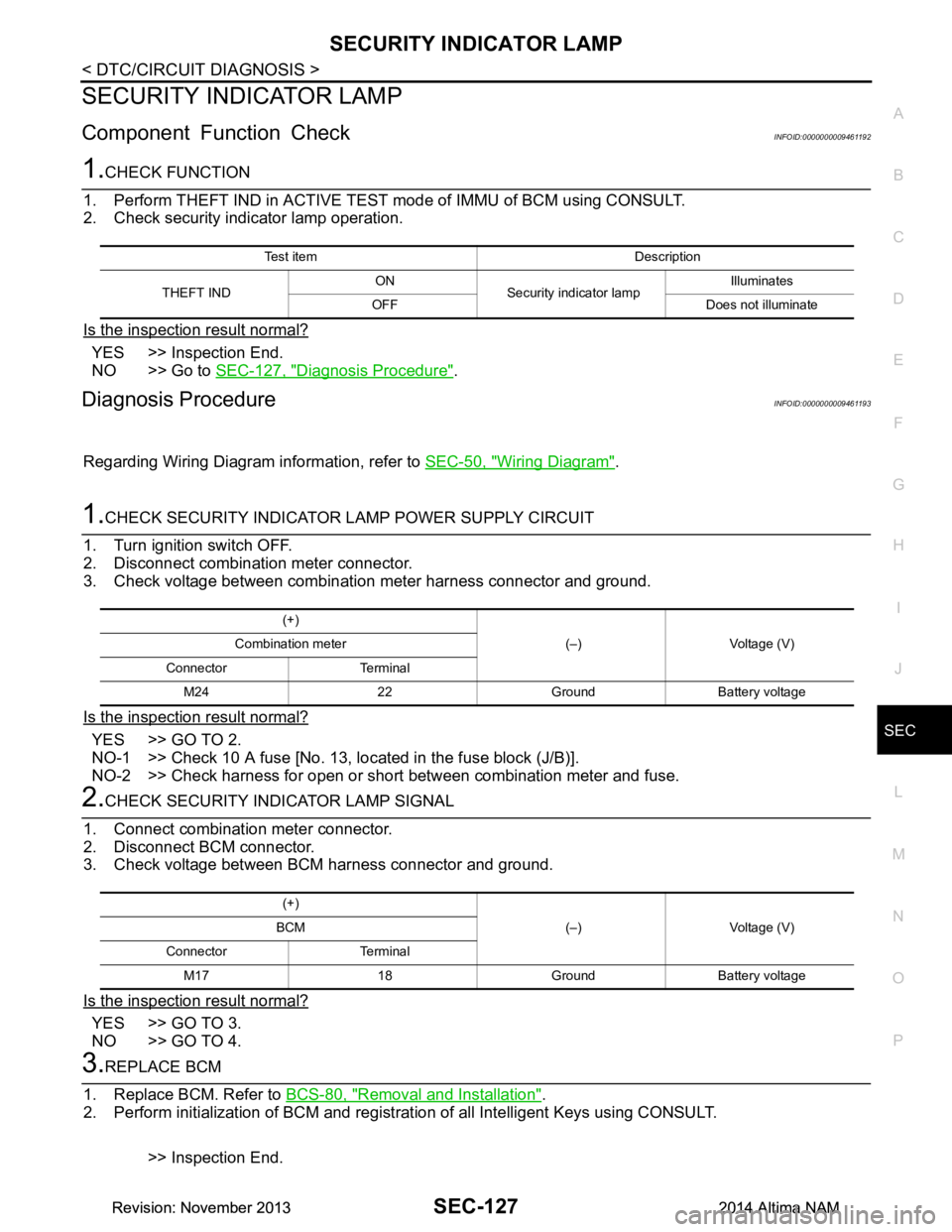
Component Function CheckINFOID:0000000009461192
1.CHECK FUNCTION
1. Perform THEFT IND in ACTIVE TEST mode of IMMU of BCM using CONSULT.
2. Check security indicator lamp operation.
Is the inspection result normal?
YES >> Inspection End.
NO >> Go to SEC-127, "Diagnosis Procedure"
.
Diagnosis ProcedureINFOID:0000000009461193
Regarding Wiring Diagram information, refer to SEC-50, "Wiring Diagram".
1.CHECK SECURITY INDICATOR LAMP POWER SUPPLY CIRCUIT
1. Turn ignition switch OFF.
2. Disconnect combination meter connector.
3. Check voltage between combination meter harness connector and ground.
Is the inspection result normal?
YES >> GO TO 2.
NO-1 >> Check 10 A fuse [No. 13, lo cated in the fuse block (J/B)].
NO-2 >> Check harness for open or short between combination meter and fuse.
2.CHECK SECURITY INDICATOR LAMP SIGNAL
1. Connect combination meter connector.
2. Disconnect BCM connector.
3. Check voltage between BCM harness connector and ground.
Is the inspection result normal?
YES >> GO TO 3.
NO >> GO TO 4.
3.REPLACE BCM
1. Replace BCM. Refer to BCS-80, "Removal and Installation"
.
2. Perform initialization of BCM and registration of all Intelligent Keys using CONSULT.
>> Inspection End.
Test item Description
THEFT IND ON
Security indicator lamp Illuminates
OFF Does not illuminate
(+) (–) Voltage (V)
Combination meter
Connector Terminal M24 22 Ground Battery voltage
(+) (–) Voltage (V)
BCM
Connector Terminal M17 18 Ground Battery voltage
Revision: November 20132014 Altima NAMRevision: November 20132014 Altima NAM
Page 3954 of 4801

ENGINE DOES NOT START WHEN INTELLIGENT KEY IS INSIDE OF VEHICLE
SEC-129
< SYMPTOM DIAGNOSIS >
C
D E
F
G H
I
J
L
M A
B
SEC
N
O P
SYMPTOM DIAGNOSIS
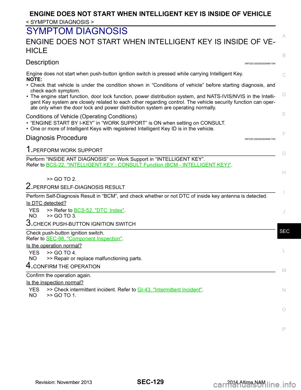
ENGINE DOES NOT START WHEN IN TELLIGENT KEY IS INSIDE OF VE-
HICLE
DescriptionINFOID:0000000009461194
Engine does not start when push-button ignition swit ch is pressed while carrying Intelligent Key.
NOTE:
• Check that vehicle is under the condition shown in “Conditions of vehicle” before starting diagnosis, and
check each symptom.
• The engine start function, door lock function, power dist ribution system, and NATS-IVIS/NVIS in the Intelli-
gent Key system are closely related to each other regar ding control. The vehicle security function can oper-
ate only when the door lock and power distribution system are operating normally.
Conditions of Vehicle (Operating Conditions)
• “ENGINE START BY I-KEY” in “WORK SUPPORT” is ON when setting on CONSULT.
• One or more of Intelligent Keys with registered Intelligent Key ID is in the vehicle.
Diagnosis ProcedureINFOID:0000000009461195
1.PERFORM WORK SUPPORT
Perform “INSIDE ANT DIAGNOSIS” on Wo rk Support in “INTELLIGENT KEY”.
Refer to BCS-22, "INTELLIGENT KEY : CONSUL T Function (BCM - INTELLIGENT KEY)"
.
>> GO TO 2.
2.PERFORM SELF-DIAGNOSIS RESULT
Perform Self-Diagnosis Result in “BCM”, and check whether or not DTC of inside key antenna is detected.
Is DTC detected?
YES >> Refer to BCS-52, "DTC Index".
NO >> GO TO 3.
3.CHECK PUSH-BUTTON IGNITION SWITCH
Check push-button ignition switch.
Refer to SEC-98, "Component Inspection"
.
Is the operation normal?
YES >> GO TO 4.
NO >> Repair or replace malfunctioning parts.
4.CONFIRM THE OPERATION
Confirm the operation again.
Is the inspection normal?
YES >> Check intermittent incident. Refer to GI-43, "Intermittent Incident".
NO >> GO TO 1.
Revision: November 20132014 Altima NAMRevision: November 20132014 Altima NAM