2014 NISSAN TEANA lock
[x] Cancel search: lockPage 3768 of 4801
SQUEAK AND RATTLE TROUBLE DIAGNOSESSE-19
< SYMPTOM DIAGNOSIS >
C
D E
F
G H
I
K L
M A
B
SE
N
O P
INSTRUMENT PANEL
Most incidents are caused by contact and movement between:
1. Cluster lid A and the instrument panel
2. Acrylic lens and combination meter housing
3. Instrument panel to front pillar finisher
4. Instrument panel to windshield
5. Instrument panel pins
6. Wiring harnesses behind the combination meter
7. A/C defroster duct and duct joint
These incidents can usually be located by tapping or moving the components to duplicate the noise or by
pressing on the components while driving to stop the noi se. Most of these incidents can be repaired by apply-
ing felt cloth tape or silicone spray (in hard to reach areas). Urethane pads can be used to insulate wiring har-
ness.
CAUTION:
Do not use silicone spray to isolate a squeak or ra ttle. If you saturate the area with silicone, you will
not be able to recheck the repair.
CENTER CONSOLE
Components to pay attention to include:
1. Shift selector assembly cover to finisher
2. A/C control unit and cluster lid C
3. Wiring harnesses behind audio and A/C control unit
The instrument panel repair and isolation pr ocedures also apply to the center console.
DOORS
Pay attention to the:
1. Finisher and inner panel making a slapping noise
2. Inside handle escutcheon to door finisher
3. Wiring harnesses tapping
4. Door striker out of alignment causing a popping noise on starts and stops
Tapping or moving the components or pressing on them wh ile driving to duplicate the conditions can isolate
many of these incidents. You can usually insulate the ar eas with felt cloth tape or insulator foam blocks from
the NISSAN Squeak and Rattle Kit (J-50397) to repair the noise.
TRUNK
Trunk noises are often caused by a loose jack or loose items put into the trunk by the owner.
In addition look for:
1. Trunk lid bumpers out of adjustment
2. Trunk lid striker out of adjustment
3. The trunk lid torsion bars knocking together
4. A loose license plate or bracket
Most of these incidents can be repaired by adjusting, se curing or insulating the item(s) or component(s) caus-
ing the noise.
SUNROOF/HEADLINING
Noises in the sunroof/headlining area can often be traced to one of the following:
1. Sunroof lid, rail, linkage or seals making a rattle or light knocking noise
2. Sun visor shaft shaking in the holder
3. Front or rear windshield touching headlining and squeaking
Again, pressing on the components to stop the noise while duplicating the conditions can isolate most of these
incidents. Repairs usually consist of insulating with felt cloth tape.
OVERHEAD CONSOLE (FRONT AND REAR)
Overhead console noises are often caused by the cons ole panel clips not being engaged correctly. Most of
these incidents are repaired by pushing up on the c onsole at the clip locations until the clips engage.
In addition look for:
Revision: November 20132014 Altima NAMRevision: November 20132014 Altima NAM
Page 3769 of 4801

SE-20
< SYMPTOM DIAGNOSIS >
SQUEAK AND RATTLE TROUBLE DIAGNOSES
1. Loose harness or harness connectors.
2. Front console map/reading lamp lens loose.
3. Loose screws at console attachment points.
SEATS
When isolating seat noise it's important to note the pos ition the seat is in and the load placed on the seat when
the noise is present. These conditions should be dupl icated when verifying and isolating the cause of the
noise.
Cause of seat noise include:
1. Headrest rods and holder
2. A squeak between the seat pad cushion and frame
3. The rear seatback lock and bracket
These noises can be isolated by moving or pressing on the suspected components while duplicating the con-
ditions under which the noise occurs. Most of thes e incidents can be repaired by repositioning the component
or applying urethane tape to the contact area.
UNDERHOOD
Some interior noise may be caused by components under the hood or on the engine wall. The noise is then
transmitted into the passenger compartment.
Causes of transmitted underhood noise include:
1. Any component installed to the engine wall
2. Components that pass through the engine wall
3. Engine wall mounts and connectors
4. Loose radiator installation pins
5. Hood bumpers out of adjustment
6. Hood striker out of adjustment
These noises can be difficult to isolate since they cannot be reached from the interior of the vehicle. The best
method is to secure, move or insulate one component at a time and test drive the vehicle. Also, engine rpm or
load can be changed to isolate the noise. Repairs can usually be made by moving, adjusting, securing, or
insulating the component causing the noise.
Revision: November 20132014 Altima NAMRevision: November 20132014 Altima NAM
Page 3773 of 4801

SE-24
< REMOVAL AND INSTALLATION >
FRONT SEAT
1. Seat cushion trim 2. Seat cushion pad 3. Seat cushion heater (if equipped)
4. Seat cushion outer finisher (RH) 5. Seat cushion inner finisher (RH front)6. Seat cushion inner finisher (RH rear)
7. Rear slide cover (RH) 8. Seat belt buckle 9. Slide cover (RH)
10. Front slide cover (RH) 11. Front slide cover (LH)12. Seat harness
13. Seat cushion outer finisher (LH) 14. Seat slide knob 15. Seat recline knob
16. Lumbar support switch (if equipped) 17. Power seat switch 18. Slide cover (LH)
19. Seat frame assembly 20. Rear slide cover (LH) 21. Seat cushion inner finisher (LH rear)
22. Seat cushion inner finisher (LH front) 23. Rear hinge cover 24. Side air bag module
25. Headrest holder (locked) 26. Headrest holder (free) 27. Seatback assembly
28. Lumbar support assembly (if equipped) 29. Headrest 30. Seatback board
A. Rear hinge cover clips B. Seatback board clips C. Side air bag module nuts
Revision: November 20132014 Altima NAMRevision: November 20132014 Altima NAM
Page 3775 of 4801
SE-26
< REMOVAL AND INSTALLATION >
FRONT SEAT
DRIVER SIDE : Removal and In stallation - Seat Assembly
INFOID:0000000009462934
REMOVAL
WARNING:
Do not leave any objects (screwdriver s, tools, etc.) on the seat during seat repair. It can lead to per-
sonal injury if the side air bag module should accidentally deploy.
CAUTION:
• When removing or installing the seat trim, handle it carefully to keep dirt out and to avoid damage.
• When checking the power seat circuit for continuity using a circuit tester, do not confuse its connec-
tor with the side air bag module connector. Such an error may cau se the air bag module to deploy.
• Do not drop, tilt, or bump the si de air bag module while installing the seat. Always handle it with
care.
• After front side air bag module inflates, the front seatback assembly must be replaced.
• When removing and installing the seat, use shop cloths to protect components from damage.
• Before removing the front seat, turn the ignition switch OFF, disconnect both battery cables and wait
at least three minutes.
1. Remove the headrest.
2. Raise seat to the highest position.
3. Slide the seat to the full rearward position.
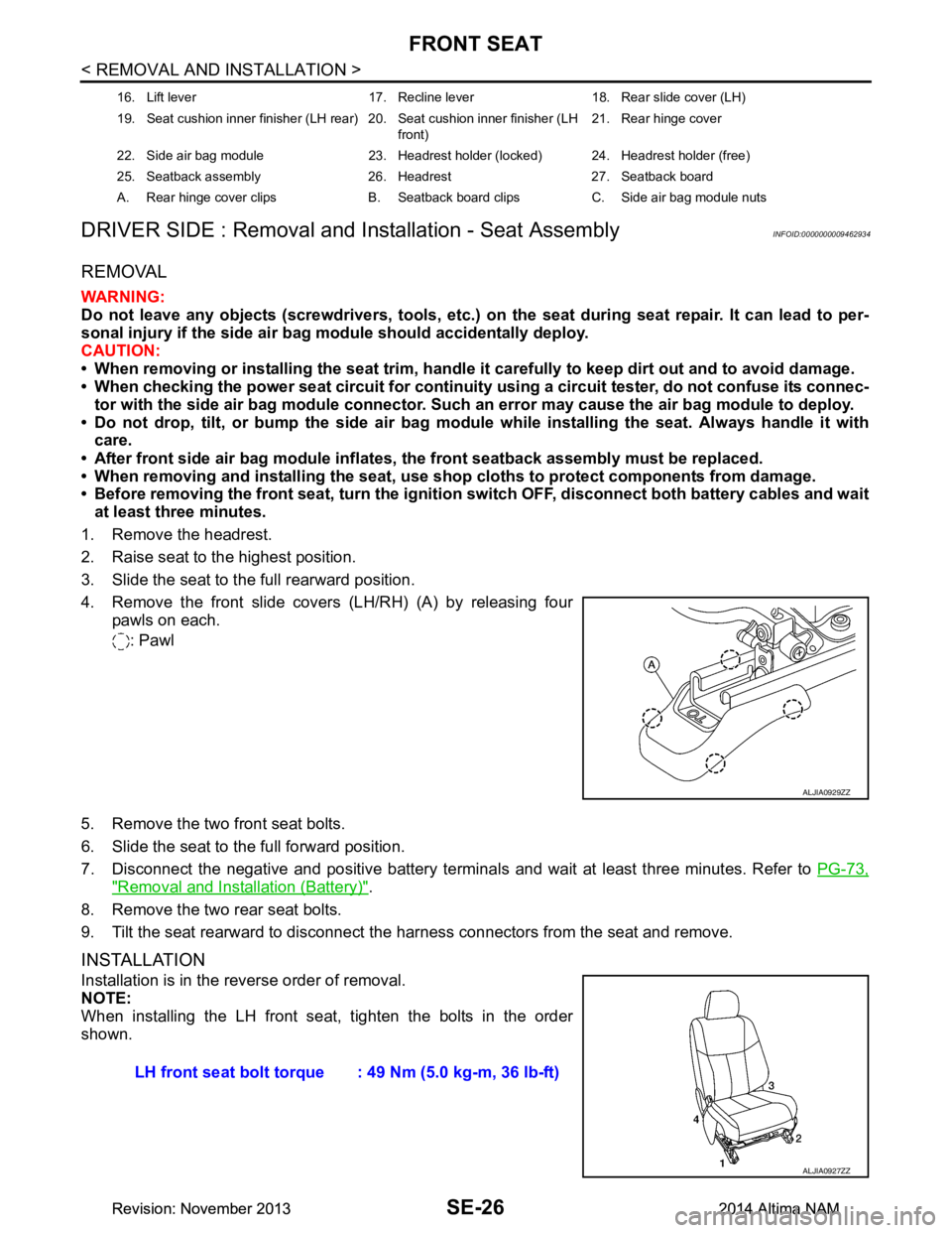
4. Remove the front slide covers (LH/RH) (A) by releasing four pawls on each.
: Pawl
5. Remove the two front seat bolts.
6. Slide the seat to the full forward position.
7. Disconnect the negative and positive battery terminal s and wait at least three minutes. Refer to PG-73,
"Removal and Installation (Battery)".
8. Remove the two rear seat bolts.
9. Tilt the seat rearward to disconnect the harness connectors from the seat and remove.
INSTALLATION
Installation is in the reverse order of removal.
NOTE:
When installing the LH front seat , tighten the bolts in the order
shown.
16. Lift lever 17. Recline lever 18. Rear slide cover (LH)
19. Seat cushion inner finisher (LH rear) 20. Seat cushion inner finisher (LH front)21. Rear hinge cover
22. Side air bag module 23. Headrest holder (locked) 24. Headrest holder (free)
25. Seatback assembly 26. Headrest 27. Seatback board
A. Rear hinge cover clips B. Seatback board clips C. Side air bag module nuts
ALJIA0929ZZ
LH front seat bolt torque : 49 Nm (5.0 kg-m, 36 lb-ft)
ALJIA0927ZZ
Revision: November 20132014 Altima NAMRevision: November 20132014 Altima NAM
Page 3779 of 4801
SE-30
< REMOVAL AND INSTALLATION >
FRONT SEAT
PASSENGER SIDE : Removal and Installation - Seat Assembly
INFOID:0000000009462938
REMOVAL
WARNING:
Do not leave any objects (screwdriver s, tools, etc.) on the seat during seat repair. It can lead to per-
sonal injury if the side air bag module should accidentally deploy.
CAUTION:
• When removing or installing the seat trim, handle it carefully to keep dirt out and to avoid damage.
• When checking the power seat circuit for continuity using a circuit tester, do not confuse its connec-
tor with the side air bag module connector. Such an error may cau se the air bag module to deploy.
• Do not drop, tilt, or bump the si de air bag module while installing the seat. Always handle it with
care.
• After front side air bag module inflates, the front seatback assembly must be replaced.
• When removing and installing the seat, use shop cloths to protect components from damage.
• Before removing the front seat, turn the ignition switch OFF, disconnect both battery cables and wait
at least three minutes.
1. Disconnect the negative and positive battery terminal s and wait at least three minutes. Refer to PG-73,
"Removal and Installation (Battery)".
2. Remove the headrest.
3. Slide the seat to the full rearward position.
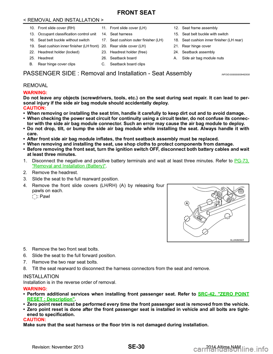
4. Remove the front slide covers (LH/RH) (A) by releasing four pawls on each.
: Pawl
5. Remove the two front seat bolts.
6. Slide the seat to the full forward position.
7. Remove the two rear seat bolts.
8. Tilt the seat rearward to disconnect the harness connectors from the seat and remove.
INSTALLATION
Installation is in the reverse order of removal.
WARNING:
• Perform additional services when instal ling front passenger seat. Refer to SRC-42, "ZERO POINT
RESET : Description".
• Zero point reset must be performed every time th e front passenger seat is removed from the vehicle.
• Zero point reset is done after the front passenger seat is installed in vehicle and all bolts are tight-
ened to specification.
CAUTION:
Make sure that the seat harness or the floor trim is not damaged during installation.
10. Front slide cover (RH) 11. Front sl ide cover (LH) 12. Seat frame assembly
13. Occupant classification control unit 14. Seat harness 15. Seat belt buckle with switch
16. Seat belt buckle without switch 17. Seat cushion outer finisher (LH) 18. Seat cushion inner finisher (LH rear)
19. Seat cushion inner finisher (LH front) 20. Rear slide cover (LH) 21. Rear hinge cover
22. Headrest holder (locked) 23. Headrest holder (free) 24. Seatback assembly
25. Headrest 26. Seatback board A. Side air bag module nuts
B. Rear hinge cover clips C. Seatback board clips
ALJIA0929ZZ
Revision: November 20132014 Altima NAMRevision: November 20132014 Altima NAM
Page 3783 of 4801

SE-34
< REMOVAL AND INSTALLATION >
REAR SEAT
7. Armrest 8. Cup holder 9. Armrest hinge finisher
10. Seatback hinge assembly (RH) 11. Seat cushion assembly 12. Seat cushion wire cover
13. Seat cushion lock 14. Seat cushion pad 15. Seat cushion trim
16. Seatback hinge (LH) 17. Seatback pad (LH) 18. Seatback trim (LH)
19. Seatback board (LH) 20. Seat belt guide (LH) 21. Rear seat bolster (LH)
22. Rear seatback assembly (LH) 23. Seatback latch assembly 24. Cable guide
A. Seatback board clips B. Armrest pivot bolt
Revision: November 20132014 Altima NAMRevision: November 20132014 Altima NAM
Page 3784 of 4801
REAR SEATSE-35
< REMOVAL AND INSTALLATION >
C
D E
F
G H
I
K L
M A
B
SE
N
O P
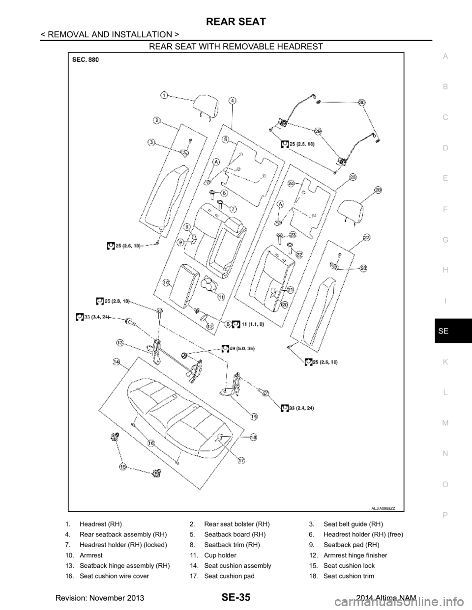
REAR SEAT WITH REMOVABLE HEADREST
ALJIA0958ZZ
1. Headrest (RH) 2. Rear seat bolster (RH) 3. Seat belt guide (RH)
4. Rear seatback assembly (RH) 5. Seatback board (RH) 6. Headrest holder (RH) (free)
7. Headrest holder (RH) (locked) 8. Seatback trim (RH) 9. Seatback pad (RH)
10. Armrest 11. Cup holder 12. Armrest hinge finisher
13. Seatback hinge assembly (RH) 14. Seat cushion assembly 15. Seat cushion lock
16. Seat cushion wire cover 17. Seat cushion pad 18. Seat cushion trim
Revision: November 20132014 Altima NAMRevision: November 20132014 Altima NAM
Page 3785 of 4801
SE-36
< REMOVAL AND INSTALLATION >
REAR SEAT
Removal and Installation - Seat Cushion Assembly
INFOID:0000000009462942
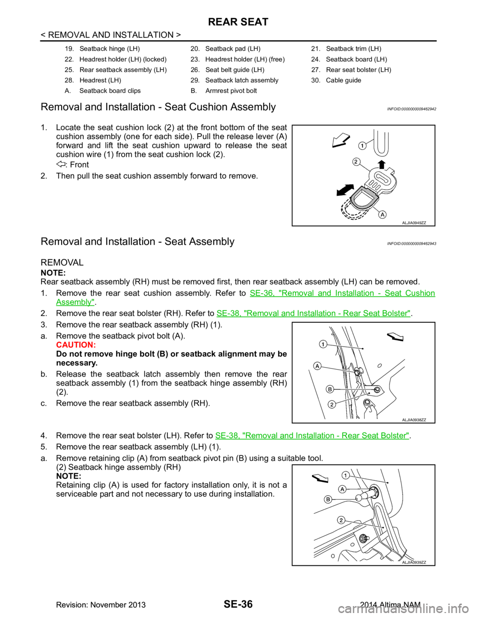
1. Locate the seat cushion lock (2) at the front bottom of the seat cushion assembly (one for each side). Pull the release lever (A)
forward and lift the seat cushion upward to release the seat
cushion wire (1) from the seat cushion lock (2).
: Front
2. Then pull the seat cushion assembly forward to remove.
Removal and Installation - Seat AssemblyINFOID:0000000009462943
REMOVAL
NOTE:
Rear seatback assembly (RH) must be removed first, then rear seatback assembly (LH) can be removed.
1. Remove the rear seat cushion assembly. Refer to SE-36, "Removal and Installation - Seat Cushion
Assembly".
2. Remove the rear seat bolster (RH). Refer to SE-38, "Removal and Installation - Rear Seat Bolster"
.
3. Remove the rear seatback assembly (RH) (1).
a. Remove the seatback pivot bolt (A). CAUTION:
Do not remove hinge bolt (B ) or seatback alignment may be
necessary.
b. Release the seatback latch assembly then remove the rear seatback assembly (1) from the seatback hinge assembly (RH)
(2).
c. Remove the rear seatback assembly (RH).
4. Remove the rear seat bolster (LH). Refer to SE-38, "Removal and Installation - Rear Seat Bolster"
.
5. Remove the rear seatback assembly (LH) (1).
a. Remove retaining clip (A) from seatback pivot pin (B) using a suitable tool. (2) Seatback hinge assembly (RH)
NOTE:
Retaining clip (A) is used for factory installation only, it is not a
serviceable part and not necessary to use during installation.
19. Seatback hinge (LH) 20. Seatback pad (LH) 21. Seatback trim (LH)
22. Headrest holder (LH) (locked) 23. Headrest holder (LH) (free) 24. Seatback board (LH)
25. Rear seatback assembly (LH) 26. Seat belt guide (LH) 27. Rear seat bolster (LH)
28. Headrest (LH) 29. Seatback latch assembly 30. Cable guide
A. Seatback board clips B. Armrest pivot bolt
ALJIA0949ZZ
ALJIA0938ZZ
ALJIA0939ZZ
Revision: November 20132014 Altima NAMRevision: November 20132014 Altima NAM