2014 NISSAN TEANA lock
[x] Cancel search: lockPage 3817 of 4801
SE-68
< UNIT DISASSEMBLY AND ASSEMBLY >
REAR SEAT
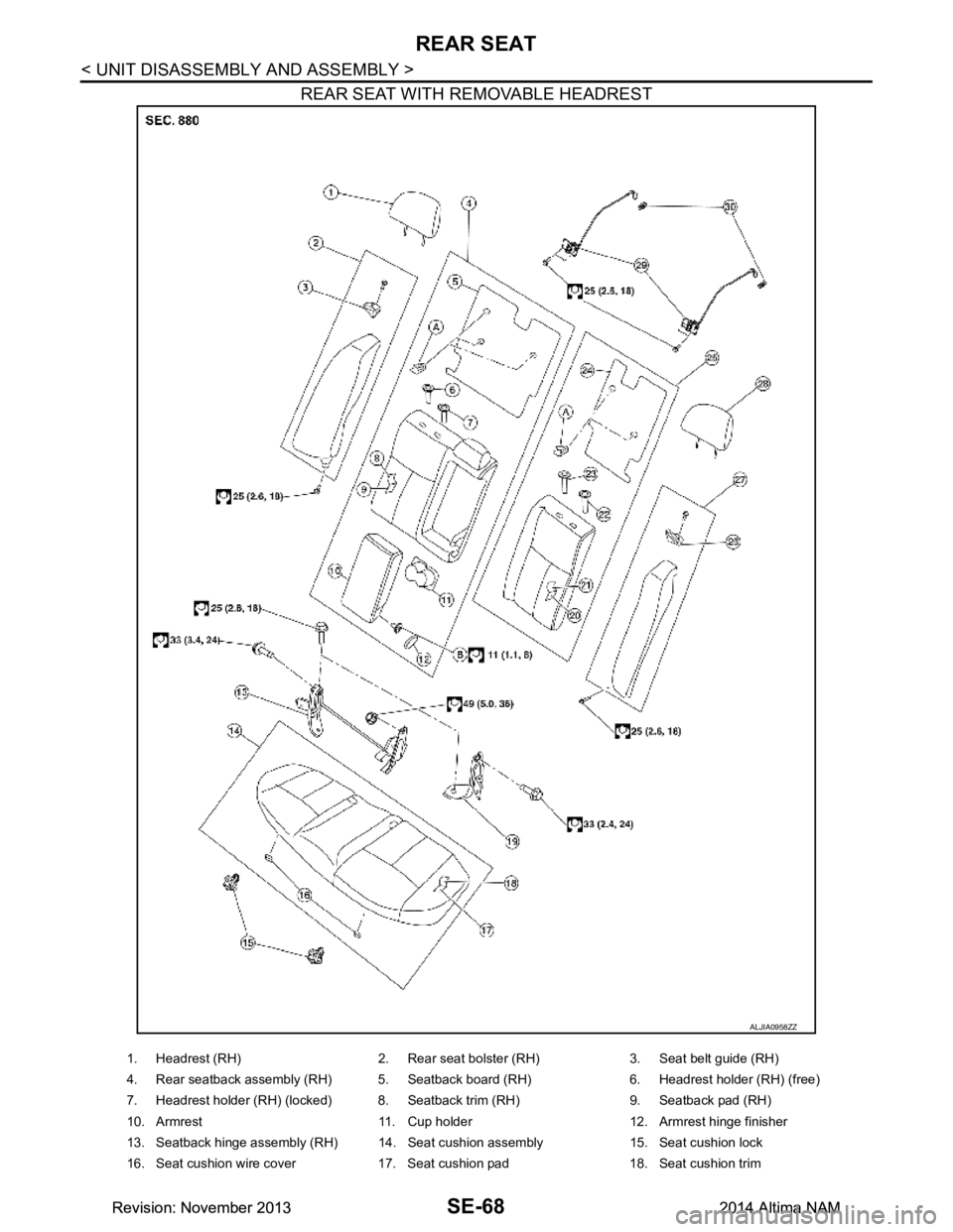
REAR SEAT WITH REMOVABLE HEADREST
ALJIA0958ZZ
1. Headrest (RH) 2. Rear seat bolster (RH) 3. Seat belt guide (RH)
4. Rear seatback assembly (RH) 5. Seatback board (RH) 6. Headrest holder (RH) (free)
7. Headrest holder (RH) (locked) 8. Seatback trim (RH) 9. Seatback pad (RH)
10. Armrest 11. Cup holder 12. Armrest hinge finisher
13. Seatback hinge assembly (RH) 14. Seat cushion assembly 15. Seat cushion lock
16. Seat cushion wire cover 17. Seat cushion pad 18. Seat cushion trim
Revision: November 20132014 Altima NAMRevision: November 20132014 Altima NAM
Page 3818 of 4801
REAR SEATSE-69
< UNIT DISASSEMBLY AND ASSEMBLY >
C
D E
F
G H
I
K L
M A
B
SE
N
O P
Disassembly and AssemblyINFOID:0000000009462955
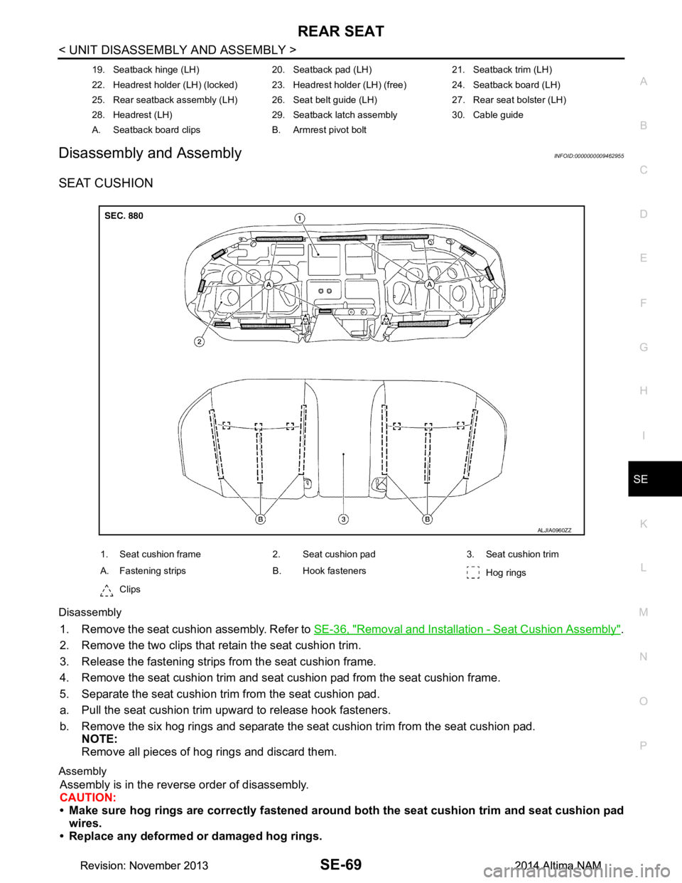
SEAT CUSHION
Disassembly
1. Remove the seat cushion assembly. Refer to SE-36, "Removal and Installation - Seat Cushion Assembly".
2. Remove the two clips that retain the seat cushion trim.
3. Release the fastening strips from the seat cushion frame.
4. Remove the seat cushion trim and seat cushion pad from the seat cushion frame.
5. Separate the seat cushion trim from the seat cushion pad.
a. Pull the seat cushion trim upward to release hook fasteners.
b. Remove the six hog rings and separate the seat cushion trim from the seat cushion pad. NOTE:
Remove all pieces of hog rings and discard them.
Assembly
Assembly is in the reverse order of disassembly.
CAUTION:
• Make sure hog rings are correctly fastened around both the seat cushion trim and seat cushion pad
wires.
• Replace any deformed or damaged hog rings.
19. Seatback hinge (LH) 20. Seatback pad (LH) 21. Seatback trim (LH)
22. Headrest holder (LH) (locked) 23. Headrest holder (LH) (free) 24. Seatback board (LH)
25. Rear seatback assembly (LH) 26. Seat belt guide (LH) 27. Rear seat bolster (LH)
28. Headrest (LH) 29. Seatback latch assembly 30. Cable guide
A. Seatback board clips B. Armrest pivot bolt
1. Seat cushion frame 2. Seat cushion pad 3. Seat cushion trim
A. Fastening strips B. Hook fasteners Hog rings
Clips
ALJIA0960ZZ
Revision: November 20132014 Altima NAMRevision: November 20132014 Altima NAM
Page 3820 of 4801
REAR SEATSE-71
< UNIT DISASSEMBLY AND ASSEMBLY >
C
D E
F
G H
I
K L
M A
B
SE
N
O P
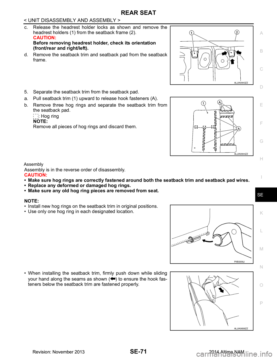
c. Release the headrest holder locks as shown and remove the headrest holders (1) from the seatback frame (2).
CAUTION:
Before removing headrest holder, check its orientation
(front/rear and right/left).
d. Remove the seatback trim and seatback pad from the seatback frame.
5. Separate the seatback trim from the seatback pad.
a. Pull seatback trim (1) upward to release hook fasteners (A).
b. Remove three hog rings and separate the seatback trim from the seatback pad.
: Hog ring
NOTE:
Remove all pieces of hog rings and discard them.
Assembly
Assembly is in the reverse order of disassembly.
CAUTION:
• Make sure hog rings are correctly fastened ar ound both the seatback trim and seatback pad wires.
• Replace any deformed or damaged hog rings.
• Make sure any old hog ring pieces are removed from seat.
NOTE:
• Install new hog rings on the seatback trim in original positions.
• Use only one hog ring in each designated location.
• When installing the seatback trim, firmly push down while sliding your hand along the seams as shown ( ) to ensure the hook fas-
teners below the seatback trim are fastened properly.
ALJIA0943ZZ
ALJIA0944ZZ
PIIB3356J
ALJIA0656ZZ
Revision: November 20132014 Altima NAMRevision: November 20132014 Altima NAM
Page 3823 of 4801
SE-74
< UNIT DISASSEMBLY AND ASSEMBLY >
REAR SEAT
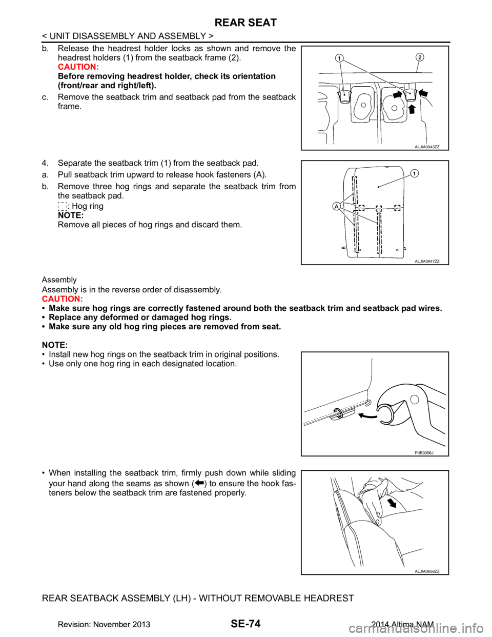
b. Release the headrest holder locks as shown and remove theheadrest holders (1) from the seatback frame (2).
CAUTION:
Before removing headrest holder, check its orientation
(front/rear and right/left).
c. Remove the seatback trim and seatback pad from the seatback frame.
4. Separate the seatback trim (1) from the seatback pad.
a. Pull seatback trim upward to release hook fasteners (A).
b. Remove three hog rings and separate the seatback trim from the seatback pad.
: Hog ring
NOTE:
Remove all pieces of hog rings and discard them.
Assembly
Assembly is in the reverse order of disassembly.
CAUTION:
• Make sure hog rings are correctly fastened ar ound both the seatback trim and seatback pad wires.
• Replace any deformed or damaged hog rings.
• Make sure any old hog ring pieces are removed from seat.
NOTE:
• Install new hog rings on the seatback trim in original positions.
• Use only one hog ring in each designated location.
• When installing the seatback trim, firmly push down while sliding
your hand along the seams as shown ( ) to ensure the hook fas-
teners below the seatback trim are fastened properly.
REAR SEATBACK ASSEMBLY (LH) - WITHOUT REMOVABLE HEADREST
ALJIA0943ZZ
ALJIA0947ZZ
PIIB3356J
ALJIA0656ZZ
Revision: November 20132014 Altima NAMRevision: November 20132014 Altima NAM
Page 3827 of 4801

SEC-2
WIRING DIAGRAM .....................................29
ENGINE START FUNCTION .......................... ...29
Wiring Diagram .................................................... ...29
NISSAN VEHICLE IMMOBILIZER SYSTEM-
NATS ............................................................... ...
40
Wiring Diagram .................................................... ...40
VEHICLE SECURITY SYSTEM .........................50
Wiring Diagram .................................................... ...50
BASIC INSPECTION ...................................63
DIAGNOSIS AND REPAIR WORK FLOW ..... ...63
Work Flow ............................................................ ...63
ADDITIONAL SERVICE WHEN REPLACING
CONTROL UNIT ............................................. ...
66
ECM ........................................................................ ...66
ECM : Description ...................................................66
ECM : Work Procedure ...........................................66
BCM ........................................................................ ...66
BCM : Description ...................................................66
BCM : Work Procedure ...........................................66
DTC/CIRCUIT DIAGNOSIS ...................... ...68
P1610 LOCK MODE ....................................... ...68
Description ........................................................... ...68
DTC Logic ...............................................................68
Diagnosis Procedure ..............................................68
P1611 ID DISCORD, IMMU-ECM ......................69
DTC Logic ............................................................ ...69
Diagnosis Procedure ..............................................69
P1612 CHAIN OF ECM-IMMU ...........................70
DTC Logic ............................................................ ...70
Diagnosis Procedure ..............................................70
P1614 CHAIN OF IMMU-KEY ...........................71
DTC Logic ............................................................ ...71
Diagnosis Procedure ..............................................71
B210B STARTER CONTROL RELAY ..............73
DTC Logic ............................................................ ...73
Diagnosis Procedure ..............................................73
B210C STARTER CONTROL RELAY ..............74
DTC Logic ............................................................ ...74
Diagnosis Procedure ..............................................74
B210D STARTER RELAY .................................76
DTC Logic ............................................................ ...76
Diagnosis Procedure ..............................................76
B210E STARTER RELAY .................................78
DTC Logic ............................................................ ...78
Diagnosis Procedure ..............................................78
B210F TRANSMISSION RANGE SWITCH .......80
Description ........................................................... ...80
DTC Logic ...............................................................80
Diagnosis Procedure ...............................................80
B2110 TRANSMISSION RANGE SWITCH .......82
Description ........................................................... ...82
DTC Logic ...............................................................82
Diagnosis Procedure ...............................................82
B2190 NATS ANTENNA AMP. .........................84
Description ........................................................... ...84
DTC Logic ...............................................................84
Diagnosis Procedure ...............................................84
B2191 DIFFERENCE OF KEY ..........................86
Description ........................................................... ...86
DTC Logic ...............................................................86
Diagnosis Procedure ...............................................86
B2192 ID DISCORD, IMMU-ECM ......................87
DTC Logic ............................................................ ...87
Diagnosis Procedure ...............................................87
B2193 CHAIN OF ECM-IMMU ..........................88
DTC Logic ............................................................ ...88
Diagnosis Procedure ...............................................88
B2195 ANTI-SCANNING ...................................89
DTC Logic ............................................................ ...89
Diagnosis Procedure ...............................................89
B2196 DONGLE UNIT .......................................90
Description ........................................................... ...90
DTC Logic ...............................................................90
Diagnosis Procedure ...............................................90
B2198 NATS ANTENNA AMP. .........................92
DTC Logic ............................................................ ...92
Diagnosis Procedure ...............................................92
B2555 STOP LAMP ...........................................94
DTC Logic ............................................................ ...94
Diagnosis Procedure ...............................................94
Component Inspection ............................................96
B2556 PUSH-BUTTON IGNITION SWITCH .....97
DTC Logic ............................................................ ...97
Diagnosis Procedure ...............................................97
Component Inspection ............................................98
B2557 VEHICLE SPEED ...................................99
DTC Logic ............................................................ ...99
Diagnosis Procedure ...............................................99
B2560 STARTER CONTROL RELAY ..............100
Description ........................................................... .100
DTC Logic .............................................................100
Diagnosis Procedure .............................................100
B2601 SHIFT POSITION ..................................101
DTC Logic ............................................................ .101
Revision: November 20132014 Altima NAMRevision: November 20132014 Altima NAM
Page 3834 of 4801

COMPONENT PARTSSEC-9
< SYSTEM DESCRIPTION >
C
D E
F
G H
I
J
L
M A
B
SEC
N
O P
If the verification result is OK, the engine can start. If the verification result is NG, the engine can not start.
IPDM E/RINFOID:0000000009461069
IPDM E/R has the starter relay and starter control relay inside. Starter relay and starter control relay are used
for the engine starting function. IPDM E/R contro ls these relays while communicating with BCM.
NATS Antenna Amp.INFOID:0000000009461070
The ID verification is performed between BCM and transponder in Intelligent Key via NATS antenna amp.
when Intelligent Key backside is contacted to push-button i gnition switch in case that Intelligent Key battery is
discharged. If the ID verification result is OK, the operation of starting engine is available.
TCMINFOID:0000000009461071
TCM transmits the shift position signal (P/N position) to BCM and IPDM E/R. And further, TCM transmits the
shift position signal (P/N position) to BCM via CAN communication.
BCM confirms the CVT shift selector position with the following 5 signals:
• P (Park) position signal from CVT shift selector (park position switch)
• P/N position signal from TCM
• P (Park) position signal from IPDM E/R (CAN)
• P/N position signal from IPDM E/R (CAN)
• P/N position signal from TCM (CAN)
IPDM E/R confirms the CVT shift select or position with the following 3 signals:
• P (Park) position signal from CVT shift selector (park position switch)
• P/N position signal from TCM
• P/N position signal from BCM (CAN)
Combination MeterINFOID:0000000009461072
Combination meter transmits the vehicle speed signal to BCM via CAN communication.
BCM also receives the vehicle speed signal from ABS ac tuator and electric unit (control unit) via CAN commu-
nication. BCM compares both signals to detect the vehicle speed.
Door SwitchINFOID:0000000009461073
Door switch detects door open/close conditi on and then transmits ON/OFF signal to BCM.
Outside Key AntennaINFOID:0000000009461074
Outside key antenna detects whether Intelligent Key is outside the vehicle and transmits the signal to BCM.
Three outside key antennas are installed in the front outside handle LH, front outside handle RH and rear
bumper.
Hood SwitchINFOID:0000000009461075
Hood switch detects that hood is open/closed, and then trans mits the signal to IPDM E/R. IPDM E/R transmits
hood switch signal to BCM via CAN communication.
Inside Key AntennaINFOID:0000000009461076
Inside key antenna detects whether Intelligent Key is inside the vehicle and transmits the signal to BCM.
Two inside key antennas are installed in the front console and rear parcel shelf.
Remote Keyless Entry ReceiverINFOID:0000000009461077
Remote keyless entry receiver receives each button oper ation signal and electronic key ID signal from Intelli-
gent Key and then transmits the signal to BCM.
Intelligent KeyINFOID:0000000009461078
Each Intelligent Key has an individual electronic ID and transmits the ID signal by request from BCM.
Carrying the Intelligent Key whose ID is registered in BCM, the driver can perform, remote start, door lock/
unlock operation, remote trunk, panic alarm and push-button ignition switch operation.
Revision: November 20132014 Altima NAMRevision: November 20132014 Altima NAM
Page 3836 of 4801
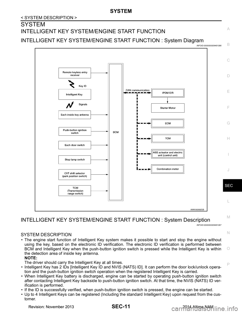
SYSTEMSEC-11
< SYSTEM DESCRIPTION >
C
D E
F
G H
I
J
L
M A
B
SEC
N
O P
SYSTEM
INTELLIGENT KEY SYSTEM/ ENGINE START FUNCTION
INTELLIGENT KEY SYSTEM/ENGINE ST ART FUNCTION : System Diagram
INFOID:0000000009461086
INTELLIGENT KEY SYSTEM/ENGINE STAR T FUNCTION : System Description
INFOID:0000000009461087
SYSTEM DESCRIPTION
• The engine start function of Intelligent Key system makes it possible to start and stop the engine without
using the key, based on the electronic ID verification. The electronic ID verification is performed between
BCM and Intelligent Key when the push-button ignition switch is pressed while the Intelligent Key is within
the detection area of inside key antenna.
NOTE:
The driver should carry the Intelligent Key at all times.
• Intelligent Key has 2 IDs [Intelligent Key ID and NVIS (NATS) ID]. It can perform the door lock/unlock opera-
tion and the push-button ignition switch operation when the registered Intelligent Key is carried.
• When Intelligent Key battery is discharged, engine c an be started by operating push-button ignition switch
after contacting Intelligent Key backside to push-button i gnition switch. At that time, the NVIS (NATS) ID ver-
ification is performed.
• If the ID is successfully verified, when push-button ignition switch is pressed, the engine can be started.
• Up to 4 Intelligent Keys can be registered (Includi ng the standard Intelligent Key) upon request from the cus-
tomer.
AWKIA2692GB
Revision: November 20132014 Altima NAMRevision: November 20132014 Altima NAM
Page 3838 of 4801

SYSTEMSEC-13
< SYSTEM DESCRIPTION >
C
D E
F
G H
I
J
L
M A
B
SEC
N
O P
Vehicle speed: 4 km/h (2.5 MPH) or more
Emergency stop operation
• Press and hold the push-button ignition switch for 2 seconds or more.
• Press the push-button ignition switch 3 times or more within 1.5 seconds.
NISSAN VEHICLE IMMOBILIZER SYSTEM-NATS
Power supply position Engine start/stop condition
Push-button ignition switch
operation frequency
Selector lever Brake pedal operation
condition
LOCK → ACC — Not depressed 1
LOCK → ACC → ON — Not depressed 2
LOCK → ACC → ON → OFF — Not depressed 3
LOCK → START
ACC → START
ON → START P or N position Depressed 1
Engine is running → OFF — — 1
Power supply position Engine start/stop condition
Push-button ignition switch
operation frequency
Selector lever Brake pedal operation
condition
Engine is running → ACC — — Emergency stop operation
Engine stall return operation while
driving N position Not depressed 1
Revision: November 20132014 Altima NAMRevision: November 20132014 Altima NAM