2014 NISSAN TEANA lock
[x] Cancel search: lockPage 4090 of 4801
B1428 SEAT BELT BUCKLE SWITCH LHSRC-97
< DTC/CIRCUIT DIAGNOSIS >
C
D E
F
G
I
J
K L
M A
B
SRC
N
O P
YES >> Refer to SRC-97, "Diagnosis Procedure".
NO >> Inspection End.
Diagnosis ProcedureINFOID:0000000009460794
1.SEAT BELT WARNING LIGHT
Turn ignition switch ON.
Does the seat belt warning lamp stay on after lamp check?
YES >> GO TO 2
NO >> • Check 10A fuse [No. 13, loca ted in the fuse block (J/B)].
• Check seat belt buckle switch LH.
• Check harness between combination meter and seat belt buckle switch LH.
• Check harness between seat belt buckle switch LH and ground.
• Check harness between combination meter and air bag diagnosis sensor unit.
• Check combination meter. Refer to MWI-27, "Fail-Safe"
.
2.SEAT BELT BUCKLE LH
Fasten the seat belt buckle LH.
Does the seat belt warning lamp go OFF?
YES >> Check harness between combination meter and air bag diagnosis sensor unit.
NO >> • Check seat belt buckle switch LH. • Check harness between combination meter and seat belt buckle switch LH.
• Check harness between combination meter and air bag diagnosis sensor unit.
Revision: November 20132014 Altima NAMRevision: November 20132014 Altima NAM
Page 4101 of 4801
SRC-108
< SYMPTOM DIAGNOSIS >
SRS AIR BAG WARNING LAMP DOES NOT TURN ON
SYMPTOM DIAGNOSIS
SRS AIR BAG WARNING LAMP DOES NOT TURN ON
AIR BAG Warning Lamp Does Not Turn OnINFOID:0000000009460813
1.CHECK METER FUSE
Check the 10A fuse [No. 13, loca ted in the fuse block (J/B)].
Is the fuse blown?
YES >> GO TO 2
NO >> GO TO 3
2.REPLACE METER FUSE AND CHECK AGAIN
Replace 10A fuse [No. 13, located in the fu se block (J/B)] and turn ignition switch ON.
Does the fuse blow again?
YES >> Replace fuse and harness.
NO >> Inspection End.
3.CHECK HARNESS CONNECTIONS BET WEEN AIR BAG DIAGNOSIS SENSOR UNIT AND COMBINA-
TION METER
Inspect the harness and connectors between the air bag diagnosis sensor unit and the combination meter.
Do the harness or connectors have any visible damage?
YES >> Replace harness.
NO >> GO TO 4
4.CHECK COMBINATION METER
Disconnect the air bag diagnosis sensor unit harness connectors and turn ignition switch ON.
Does AIR BAG warning lamp turn on?
YES >> Replace the air bag diagnosis sensor unit. Refer to SR-26, "Removal and Installation".
NO >> Replace the combination meter. Refer to MWI-82, "Removal and Installation"
.
Revision: November 20132014 Altima NAMRevision: November 20132014 Altima NAM
Page 4102 of 4801
SRS AIR BAG WARNING LAMP DOES NOT TURN OFF
SRC-109
< SYMPTOM DIAGNOSIS >
C
D E
F
G
I
J
K L
M A
B
SRC
N
O P
SRS AIR BAG WARNING LAMP DOES NOT TURN OFF
AIR BAG Warning Lamp Does Not Turn OffINFOID:0000000009460814
1.CHECK CONDITION OF AIR BAG MODULE
Inspect for any deployed air bag modules or seat belt pre-tensioners.
Are any air bag modules or seat belt pre-tensioners deployed?
YES >> Refer to SR-5, "For Frontal Collision" or SR-7, "For Side and Rollover Collision".
NO >> GO TO 2
2.CHECK THE AIR BAG FUSE
Check 10A fuse [No. 32, locat ed in the fuse block (J/B)].
Is the fuse blown?
YES >> GO TO 3
NO >> GO TO 4
3.CHECK AIR BAG FUSE AGAIN
Replace 10A fuse [No. 32, located in the fu se block (J/B)] and turn ignition switch ON.
Does the fuse blow again?
YES >> Replace fuse and harness.
NO >> Inspection End.
4.CHECK AIR BAG DIAGNOSIS SENSOR UNIT
Connect CONSULT.
Is
“AIR BAG” displayed on CONSULT?
YES >> GO TO 5
NO >> Visually inspect the air bag diagnosis sensor unit harness connections. If the connections are OK,
replace the air bag diagnosis sensor unit. Refer to SR-26, "Removal and Installation"
.
5.CHECK HARNESS CONNECTION
Check for loose connections between the combination meter and the air bag diagnosis sensor unit.
Are there any loose connections?
YES >> Properly connect the combination meter and air bag diagnosis sensor unit harness connectors. If AIR BAG warning lamp still does not tu rn off, replace the wiring harness.
NO >> Replace air bag diagnosis sensor unit. Refer to SR-26, "Removal and Installation"
.
Revision: November 20132014 Altima NAMRevision: November 20132014 Altima NAM
Page 4103 of 4801
SRC-110
< SYMPTOM DIAGNOSIS >
SEAT BELT WARNING SYSTEM
SEAT BELT WARNING SYSTEM
Seat Belt Warning System Does Not FunctionINFOID:0000000009460815
(For US/CAN models only)
1.SEAT BELT WARNING LIGHT
Turn ignition switch ON.
Does the seat belt warning lamp come ON?
YES >> GO TO 2
NO >> • Check 10A fuse [No. 13, located in the fuse block (J/B)].
• Check seat belt buckle switch (driver seat).
• Check harness between combination meter and seat belt buckle switch (driver seat).
• Check combination meter. Refer to MWI-27, "Fail-Safe"
.
2.SEAT BELT BUCKLE (DRIVER SEAT)
Fasten the seat belt buckle (driver seat).
Does the seat belt warning lamp go OFF?
YES >> GO TO 3
NO >> • Check seat belt buckle switch (driver seat). • Check harness between combination meter and seat belt buckle switch (driver seat).
3.OCCUPANT CLASSIFICATION SYSTEM
Have a helper sit in the passenger seat.
Does the seat belt warning lamp go ON?
YES >> GO TO 4
NO >> • Check occupant classification system. Refer to SRC-12, "OCCUPANT CLASSIFICATION SYS-
TEM : System Description".
• Check harness between occupant classification control unit and air bag diagnosis sensor unit.
4.SEAT BELT BUCKLE (PASSENGER SEAT)
Fasten the seat belt buckle (passenger seat).
Does the seat belt warning lamp go OFF?
YES >> System OK.
NO >> • Check seat belt buckle switch (passenger seat). • Check harness between seat belt buckle switch (passenger seat) and air bag diagnosis sensorunit.
• Replace air bag diagnosis sensor unit. Refer to SR-26, "Removal and Installation"
.
Revision: November 20132014 Altima NAMRevision: November 20132014 Altima NAM
Page 4118 of 4801
POWER STEERING FLUIDST-15
< BASIC INSPECTION >
C
D E
F
H I
J
K L
M A
B
ST
N
O P
POWER STEERING FLUID
InspectionINFOID:0000000009461251
FLUID LEVEL
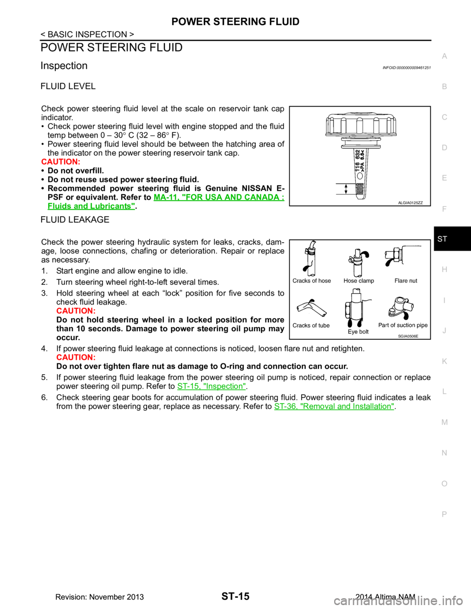
Check power steering fluid level at the scale on reservoir tank cap
indicator.
• Check power steering fluid level with engine stopped and the fluid temp between 0 – 30 ° C (32 – 86 ° F).
• Power steering fluid level should be between the hatching area of the indicator on the power steering reservoir tank cap.
CAUTION:
• Do not overfill.
• Do not reuse used power steering fluid.
• Recommended power steering fluid is Genuine NISSAN E-
PSF or equivalent. Refer to MA-11, "FOR USA AND CANADA :
Fluids and Lubricants".
FLUID LEAKAGE
Check the power steering hydraulic system for leaks, cracks, dam-
age, loose connections, chafing or det erioration. Repair or replace
as necessary.
1. Start engine and allow engine to idle.
2. Turn steering wheel right-to-left several times.
3. Hold steering wheel at each “lock” position for five seconds to check fluid leakage.
CAUTION:
Do not hold steering wheel in a locked position for more
than 10 seconds. Damage to power steering oil pump may
occur.
4. If power steering fluid leakage at connections is noticed, loosen flare nut and retighten.
CAUTION:
Do not over tighten flare nut as damage to O-ring and connection can occur.
5. If power steering fluid leakage from the power steer ing oil pump is noticed, repair connection or replace
power steering oil pump. Refer to ST-15, "Inspection"
.
6. Check steering gear boots for accumulation of power st eering fluid. Power steering fluid indicates a leak
from the power steering gear, replace as necessary. Refer to ST-36, "Removal and Installation"
.
ALGIA0125ZZ
SGIA0506E
Revision: November 20132014 Altima NAMRevision: November 20132014 Altima NAM
Page 4119 of 4801
ST-16
< BASIC INSPECTION >
STEERING WHEEL
STEERING WHEEL
InspectionINFOID:0000000009461252
CONDITION OF INSTALLATION
• Check installation condition of power steering gear assembly, front suspension, front drive shaft and steering
column.
• Check if movement exists when steering wheel is mo ved up and down, to the left and right and to the axial
direction.
• Verify that the power steering gear nuts are tightened to specification. Refer to ST-36, "Exploded View"
.
STEERING WHEEL PLAY
1. Turn tires straight ahead, start engine, then turn steer ing wheel to the left and right lightly. Measure steer-
ing wheel movement on the outer circumference of the steering wheel when it is turned to the point where
tires start moving.
NEUTRAL POSITION ON STEERING WHEEL
• Check neutral position on steering wheel after confirming that front wheel alignment is correct. Refer to FSU-
25, "Wheel Alignment (Unladen*1)".
1. Turn tires straight ahead, check if st eering wheel is in the neutral position.
2. If it is not in the neutral position, remo ve steering wheel and reinstall it correctly.
3. If the neutral position cannot be attained by repositi oning the steering wheel two teeth or less on steering
stem, loosen tie-rod lock nuts of power steering gear outer sockets, then adjust tie-rods by the same
amount in the opposite direction.
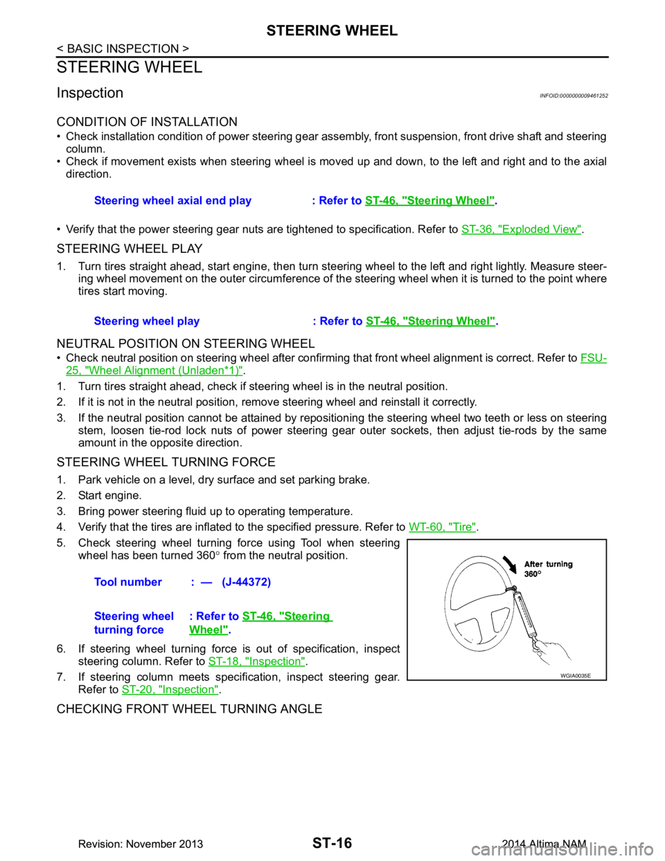
STEERING WHEEL TURNING FORCE
1. Park vehicle on a level, dry surface and set parking brake.
2. Start engine.
3. Bring power steering fluid up to operating temperature.
4. Verify that the tires are inflated to the specified pressure. Refer to WT-60, "Tire"
.
5. Check steering wheel turning force using Tool when steering wheel has been turned 360 ° from the neutral position.
6. If steering wheel turning force is out of specification, inspect steering column. Refer to ST-18, "Inspection"
.
7. If steering column meets specification, inspect steering gear. Refer to ST-20, "Inspection"
.
CHECKING FRONT WHEEL TURNING ANGLE
Steering wheel axial end play : Refer to ST-46, "Steering Wheel".
Steering wheel play : Refer to ST-46, "Steering Wheel"
.
Tool number : — (J-44372)
Steering wheel
turning force : Refer to
ST-46, "Steering
Wheel".
WGIA0035E
Revision: November 20132014 Altima NAMRevision: November 20132014 Altima NAM
Page 4124 of 4801
POWER SUPPLY AND GROUND CIRCUITST-21
< DTC/CIRCUIT DIAGNOSIS >
C
D E
F
H I
J
K L
M A
B
ST
N
O P
DTC/CIRCUIT DIAGNOSIS
POWER SUPPLY AND GROUND CIRCUIT
A/C AUTO AMP.
A/C AUTO AMP. : Diagnosis ProcedureINFOID:0000000009952472
Regarding Wiring Diagram information, refer to HAC-34, "Wiring Diagram".
1.CHECK FUSE
Check fuses [No. 14, 25 and 30, loca ted in the fuse block (J/B)].
NOTE:
Refer to PG-70, "Terminal Arrangement"
.
Is the inspection result normal?
YES >> GO TO 2.
NO >> Replace the blown fuse after repairing the affected circuit.
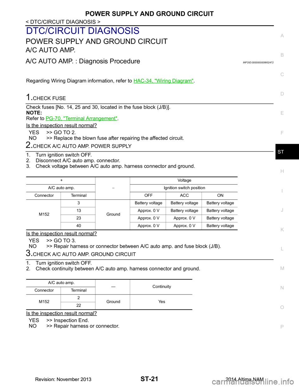
2.CHECK A/C AUTO AMP. POWER SUPPLY
1. Turn ignition switch OFF.
2. Disconnect A/C auto amp. connector.
3. Check voltage between A/C auto amp. harness connector and ground.
Is the inspection result normal?
YES >> GO TO 3.
NO >> Repair harness or connector between A/C auto amp. and fuse block (J/B).
3.CHECK A/C AUTO AMP. GROUND CIRCUIT
1. Turn ignition switch OFF.
2. Check continuity between A/C aut o amp. harness connector and ground.
Is the inspection result normal?
YES >> Inspection End.
NO >> Repair harness or connector.
+
− Voltag e
A/C auto amp. Ignition switch position
Connector Terminal OFF ACC ON
M152 3
GroundBattery voltage Battery voltage Battery voltage
13 Approx. 0 V Battery voltage Battery voltage
23 Approx. 0 V Approx. 0 V Battery voltage
40 Approx. 0 V Approx. 0 V Battery voltage
A/C auto amp. — Continuity
Connector Terminal
M152 2
Ground Yes
22
Revision: November 20132014 Altima NAMRevision: November 20132014 Altima NAM
Page 4132 of 4801
NOISE, VIBRATION AND HARSHNESS (NVH) TROUBLESHOOTINGST-29
< SYMPTOM DIAGNOSIS >
C
D E
F
H I
J
K L
M A
B
ST
N
O P
NOISE, VIBRATION AND HARSHN ESS (NVH) TROUBLESHOOTING
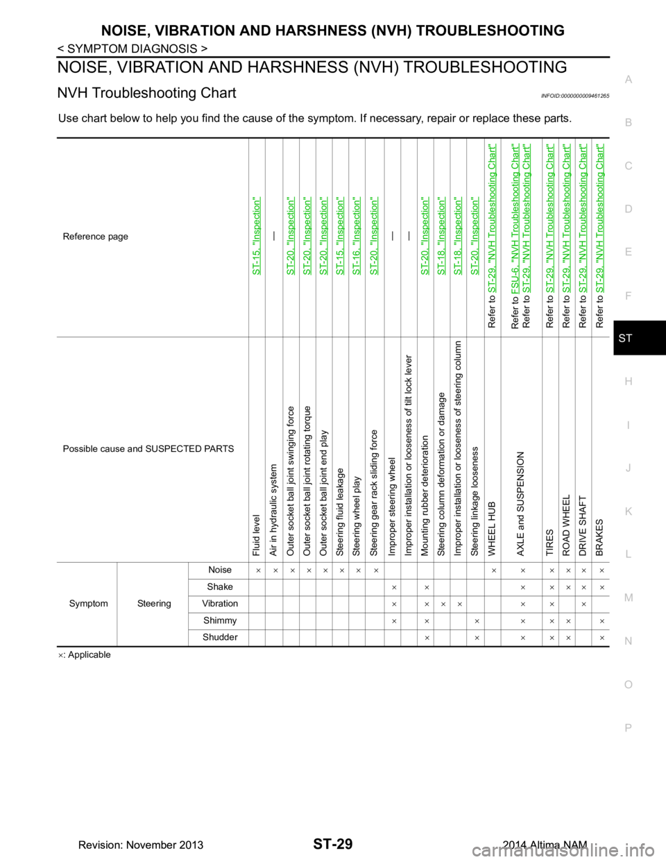
NVH Troubleshooting ChartINFOID:0000000009461265
Use chart below to help you find the cause of the symptom. If necessary, repair or replace these parts.
×: Applicable
Reference page
ST-15, "Inspection"
—
ST-20, "Inspection"
ST-20, "Inspection"ST-20, "Inspection"ST-15, "Inspection"ST-16, "Inspection"ST-20, "Inspection"
—
—
ST-20, "Inspection"
ST-18, "Inspection"ST-18, "Inspection"ST-20, "Inspection"
Refer to ST-29, "NVH Troubleshooting Chart"Refer to FSU-6, "NVH Troubleshooting Chart"
Refer to ST-29, "NVH Troubleshooting Chart"
Refer to ST-29, "NVH Troubleshooting Chart"
Refer to ST-29, "NVH Troubleshooting Chart"
Refer to ST-29, "NVH Troubleshooting Chart"
Refer to ST-29, "NVH Troubleshooting Chart"
Possible cause and SUSPECTED PARTS
Fluid level
Air in hydraulic system
Outer socket ball joint swinging force
Outer socket ball joint rotating torque
Outer socket ball joint end play
Steering fluid leakage
Steering wheel play
Steering gear rack sliding force
Improper steering wheel
Improper installation or looseness of tilt lock lever
Mounting rubber deterioration
Steering column deformation or damage
Improper installation or looseness of steering column
Steering linkage looseness
WHEEL HUB
AXLE and SUSPENSION
TIRES
ROAD WHEEL
DRIVE SHAFT
BRAKES
Symptom Steering Noise
× × ××××× × × × ××× ×
Shake ×× ×××××
Vibration × ××× × × ×
Shimmy ×× × ××× ×
Shudder ××××××
Revision: November 20132014 Altima NAMRevision: November 20132014 Altima NAM